
Related Manuals for Powerware Uninterruptible Power Supply


Summary of Contents for Powerware Uninterruptible Power Supply
-
Page 1: Installation And Operation
Uninterruptible Power Supply 500 kVA - - 750 kVA Installation and Operation Manual 164201244 Rev. D... -
Page 2: Important Safety Instructions
WARNING: This is a product for restricted sales distribution to informed partners. Installation restrictions or additional measures may be needed to prevent disturbances. Powerware 9315 (500 kVA- -750 kVA) Installation and Operation 164201244 REV. D 030101... -
Page 3: Table Of Contents
........2---8 Powerware 9315 (500 kVA- -750 kVA) Installation and Operation 164201244 REV. D 030101... - Page 4 Symbols, Controls, and Indicators ......10---6 Powerware 9315 (500 kVA- -750 kVA) Installation and Operation 164201244 REV. D 030101...
- Page 5 ......13---6 Powerware 9315 (500 kVA- -750 kVA) Installation and Operation 164201244 REV. D 030101...
- Page 6 ........15---15 Powerware 9315 (500 kVA- -750 kVA) Installation and Operation 164201244 REV. D 030101...
- Page 7 ..........W ---1 Powerware 9315 (500 kVA- -750 kVA) Installation and Operation 164201244 REV. D 030101...
-
Page 8: List Of Figures
........15---9 Powerware 9315 (500 kVA- -750 kVA) Installation and Operation viii... - Page 9 Table 15---3. Options Available for Each Communication Port ....15---5 Powerware 9315 (500 kVA- -750 kVA) Installation and Operation 164201244 REV. D 030101...
- Page 10 This Page Intentionally Left Blank. Powerware 9315 (500 kVA- -750 kVA) Installation and Operation 164201244 REV. D 030101...
-
Page 11: Introduction
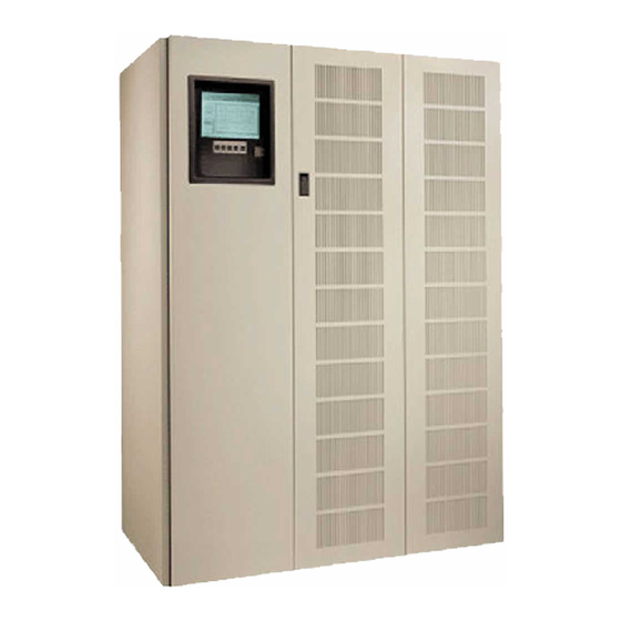
Introduction Congratulations on your purchase of a Powerware 9315 (500 kVA---750 kVA) Uninterruptable Power Supply! The Powerware online power protection system is used to prevent loss of valuable electronic information, minimize equipment downtime, and/or minimize the adverse effect on equipment production due to unexpected power problems. -
Page 12: Basic System Configurations
Chapter 3 -- Installing Batteries -- provides battery safety and installation information. · Chapter 4 -- Installing a Remote Battery Disconnect -- describes how to install the UPS battery disconnect. Powerware 9315 (500 kVA- -750 kVA) Installation and Operation 164201244 REV. D 030101... - Page 13 · Warranty -- provides the Powerware warranty for this product. Read through each procedure before you begin. Perform only those procedures that apply to the UPS system you are installing or operating.
-
Page 14: Conventions Used In This Manual
Battery maintenance or battery replacement should be performed only by authorized service personnel. · Observe all DANGER, CAUTION, and WARNING notices affixed to the inside and outside of the equipment. Powerware 9315 (500 kVA- -750 kVA) Installation and Operation 164201244 REV. D 030101... -
Page 15: For More Information
SBM and how to connect optional remote accessories to your SBM; provides information about enabling, disabling, and customizing building alarms. Contact your local Powerware Field Service office for information on how to obtain copies of this manual. Getting Help If you need to schedule initial startup, need regional locations and telephone numbers,... - Page 16 This Page Intentionally Left Blank. Powerware 9315 (500 kVA- -750 kVA) Installation and Operation 164201244 REV. D 030101...
-
Page 17: Section I
Section I Installation Powerware 9315 (500 kVA- -750 kVA) Installation and Operation 164201244 REV. D 030101... - Page 18 This Page Intentionally Left Blank. Powerware 9315 (500 kVA- -750 kVA) Installation and Operation 164201244 REV. D 030101...
-
Page 19: Getting Started
The operating environment must meet the size and weight requirements shown in Drawing 164201244---8, and Table P of Appendix A. Powerware 9315 (500 kVA- -750 kVA) Installation and Operation 1--1 164201244 REV. D 030101... -
Page 20: Environment Considerations
EPO and optional accessories (such as building alarms, and monitoring interface) should be connected at the customer interface panels and terminal blocks located inside the UPS. Powerware 9315 (500 kVA- -750 kVA) Installation and Operation 1--2 164201244 REV. D 030101... -
Page 21: Inspecting And Unpacking Each Cabinet
4.6m (15 ft) on each side for removing the cabinets from the pallets. If outer packaging is secured with steel bands, cut and remove the bands from around each cabinet. Powerware 9315 (500 kVA- -750 kVA) Installation and Operation 1--3 164201244 REV. D 030101... - Page 22 After removing the protective covering, inspect the contents for any evidence of physical damage, and compare each item with the Bill of Lading. If damage has occurred or shortages are evident, contact the Powerware, Inc. Customer Service Department immediately to determine the extent of the damage and its impact upon further installation.
-
Page 23: Installing The Ups System
Details about control wiring are provided in each procedure for connecting options and features. Drawing 164201244---2 and Tables K through O in Appendix A identify the control wiring terminations. Powerware 9315 (500 kVA- -750 kVA) Installation and Operation 2--1 164201244 REV. D 030101... -
Page 24: Single Module Installation
Connect negative DC Link power wiring to the inverter input. Connect two cables to each inverter. Refer to Appendix A of this manual for terminal locations and tightening torque. Reinstall inverter input section plastic shield. Powerware 9315 (500 kVA- -750 kVA) Installation and Operation 2--2 164201244 REV. D 030101... -
Page 25: Installing Ups External Power And Control Wiring
Connect phase A, B, and C and Neutral power wiring from MBC output to critical load. Refer to Appendix A of this manual for wiring and termination requirements and wiring access information Powerware 9315 (500 kVA- -750 kVA) Installation and Operation 2--3 164201244 REV. D 030101... -
Page 26: Installing Input/Rectifier Customer Connections
Be sure the UPS system is turned off and all power sources are removed. (See the operation section of this manual for shutdown instructions.) Refer to Appendix A of this manual for terminal assignments, and wiring and terminal requirements. Powerware 9315 (500 kVA- -750 kVA) Installation and Operation 2--4 164201244 REV. D 030101... -
Page 27: Multi-Module Installation 2
Braid is secured at the factory to the Output/Inverter cabinet mounting stud. Connect ground braid to Input/Rectifier cabinet mounting stud and secure. Powerware 9315 (500 kVA- -750 kVA) Installation and Operation 2--5 164201244 REV. D 030101... -
Page 28: Prepare For Installing Optional Accessories
Refer to paragraph 2.2.4 for procedure. 2.3.5 Installing Output/Inverter Customer Connections Refer to paragraph 2.2.5 for procedure. 2.3.6 Prepare for Installing Optional Accessories Refer to paragraph 2.2.6 for procedure. Powerware 9315 (500 kVA- -750 kVA) Installation and Operation 2--6 164201244 REV. D 030101... -
Page 29: Initial Startup
Installation Checklist to be sure you have completed all applicable equipment installation. NOTE: The Installation Checklist MUST be completed prior to starting the UPS system for the first time. Powerware 9315 (500 kVA- -750 kVA) Installation and Operation 2--7 164201244 REV. D 030101... -
Page 30: Installation Checklist
UPS and battery cabinet. (OPTIONAL) Debris shields covering ventilation grills removed from all cabinets. Startup and operational checks performed by authorized service personnel. Powerware 9315 (500 kVA- -750 kVA) Installation and Operation 2--8 164201244 REV. D 030101... -
Page 31: Rev. D
Notes ________________________________________________________________________________ ________________________________________________________________________________ ________________________________________________________________________________ ________________________________________________________________________________ ________________________________________________________________________________ ________________________________________________________________________________ ________________________________________________________________________________ ________________________________________________________________________________ ________________________________________________________________________________ ________________________________________________________________________________ ________________________________________________________________________________ ________________________________________________________________________________ ________________________________________________________________________________ Powerware 9315 (500 kVA- -750 kVA) Installation and Operation 2--9 164201244 REV. D 030101... - Page 32 This Page Intentionally Left Blank. Powerware 9315 (500 kVA- -750 kVA) Installation and Operation 2--10 164201244 REV. D 030101...
-
Page 33: Installing Batteries 3
A battery can cause electrical shock, burn from high short-circuit current, or fire. Take proper precautions when working with batteries. Powerware 9315 (500 kVA- -750 kVA) Installation and Operation 3--1 164201244 REV. D 030101... -
Page 34: Installing Batteries
2. The DC input to the UPS is protected by internal fuses F30 and F31. Install batteries in accordance with the battery and battery rack manufacturers instructions. Powerware 9315 (500 kVA- -750 kVA) Installation and Operation 3--2 164201244 REV. D 030101... -
Page 35: Installing A Remote Battery Disconnect 4
UPS or battery string, the disconnect should be set to the OFF position. Operating Handle ON Position Operating Handle OFF Position Figure 4 ---1. Remote Battery Disconnect Enclosure Powerware 9315 (500 kVA- -750 kVA) Installation and Operation 4--1 164201244 REV. D 030101... -
Page 36: Installation Notes
S Table 4---1 in this chapter details the power cable terminations. S The remote battery disconnect weighs approximately 60.3 kg (133 lb). It has an ampere interrupting capacity (AIC) of 100,000 at 500 VDC. Powerware 9315 (500 kVA- -750 kVA) Installation and Operation 4--2 164201244 REV. D 030101... -
Page 37: Table 4---1. Remote Battery Disconnect Power Terminations
76 (56) (jumper) (jumper) Table 4 -- 2. Remote Battery Disconnect Circuit Breaker Ratings UPS Model Circuit Breaker Rating DC Voltage 9315---750/500 1600 9315---750/625 2000 9315---750/750 2000 Powerware 9315 (500 kVA- -750 kVA) Installation and Operation 4--3 164201244 REV. D 030101... - Page 38 This Page Intentionally Left Blank. Powerware 9315 (500 kVA- -750 kVA) Installation and Operation 4--4 164201244 REV. D 030101...
-
Page 39: Installation Procedures
UPS Output/Inverter cabinet. Refer to Appendix A, Drawing 164201244---7, for conduit landing area and terminal board location, and Drawing 164201244---2 for terminal wiring assignments. Powerware 9315 (500 kVA- -750 kVA) Installation and Operation 5--1 164201244 REV. D 030101... -
Page 40: Table 5---1. Remote Epo Wire Terminations
Table 5---2. Remote EPO switch wiring must be in accordance with UL Class II requirements. Secure the UPS by reversing all steps taken to prepare it for Remote EPO installation. Powerware 9315 (500 kVA- -750 kVA) Installation and Operation 5--2 164201244 REV. D 030101... -
Page 41: Installing A Remote Monitor Panel 6
Table 6---1. Optional Monitoring Accessories Number and Type of Accessories Permitted Remote Monitor Panel Relay Interface Module Supervisory Contact Module — — — — — — — — — Powerware 9315 (500 kVA- -750 kVA) Installation and Operation 6--1 164201244 REV. D 030101... - Page 42 FLUSH MOUNT SURFACE MOUNT (FOR HANGING) WIRES MUST BE TWISTED Figure 6 ---1. Remote Monitor Panel (RMP) Powerware 9315 (500 kVA- -750 kVA) Installation and Operation 6--2 164201244 REV. D 030101...
-
Page 43: To Install An Rmp
Customer Interface Panel. Connect to Port 1 (DB---9) on Customer Interface Panel FUSE TERMINAL BLOCK (TB3) Figure 6 ---2. Terminal Block Bracket Powerware 9315 (500 kVA- -750 kVA) Installation and Operation 6--3 164201244 REV. D 030101... -
Page 44: Table 6
If you are installing an RIM or SCM in addition to an RMP , proceed to Chapter 7 or 8, respectively; otherwise, secure the UPS cabinet by reversing the steps contained in paragraph 2.2.6. Powerware 9315 (500 kVA- -750 kVA) Installation and Operation 6--4 164201244 REV. D 030101... - Page 45 164201244---11 in Appendix A for enclosure dimensions and wiring knockouts. FLUSH MOUNT SURFACE MOUNT FOR HANGING Relay Interface Module CONTINUES 15-PIN D-SUB AT UPS CONNECTORS Figure 7 ---1. Relay Interface Module Powerware 9315 (500 kVA- -750 kVA) Installation and Operation 7--1 164201244 REV. D 030101...
- Page 46 Customer Interface Panel. Connect to Port 1 (DB---9) on Customer Interface Panel FUSE TERMINAL BLOCK (TB3) Figure 7 ---2. Terminal Block Bracket Powerware 9315 (500 kVA- -750 kVA) Installation and Operation 7--2 164201244 REV. D 030101...
-
Page 47: Table 7
If you are installing an RMP or SCM in addition to an RIM, proceed to Chapter 6 or 8, respectively; otherwise, secure the UPS cabinet by reversing the steps contained in paragraph 2.2.6. Powerware 9315 (500 kVA- -750 kVA) Installation and Operation 7--3 164201244 REV. D 030101... - Page 48 This Page Intentionally Left Blank. Powerware 9315 (500 kVA- -750 kVA) Installation and Operation 7--4 164201244 REV. D 030101...
- Page 49 Refer to Appendix A, Drawing 164201244---12, for enclosure dimensions, side views, and knockout patterns. SURFACE MOUNT (FOR HANGING) WIRES MUST BE TWISTED Figure 8 ---1. Supervisory Contact Module Powerware 9315 (500 kVA- -750 kVA) Installation and Operation 8--1 164201244 REV. D 030101...
- Page 50 Customer Interface Panel. Connect to Port 1 (DB---9) on Customer Interface Panel FUSE TERMINAL BLOCK (TB3) Figure 8 ---2. Terminal Block Bracket Powerware 9315 (500 kVA- -750 kVA) Installation and Operation 8--2 164201244 REV. D 030101...
-
Page 51: Figure 8
If you are installing an RMP or RIM in addition to an SCM, proceed to Chapter 6 or 7, respectively; otherwise, secure the UPS cabinet by reversing the steps contained in paragraph 2.2.6. Powerware 9315 (500 kVA- -750 kVA) Installation and Operation 8--3 164201244 REV. D 030101... - Page 52 Note: Supervisory contacts are rated at 2.0 amps at 28 Vdc or 120 Vac and 0.15 amp at 115 Vdc. Supervisory contacts require external power supply. Internal 24 Vdc is not capable of supplying contact current. Figure 8 ---3. Supervisory Contact Module TB2 Powerware 9315 (500 kVA- -750 kVA) Installation and Operation 8--4 164201244 REV. D 030101...
- Page 53 Section II Operation Powerware 9315 (500 kVA- -750 kVA) Installation and Operation 164201244 REV. D 030101...
- Page 54 This Page Intentionally Left Blank. Powerware 9315 (500 kVA- -750 kVA) Installation and Operation 164201244 REV. D 030101...
-
Page 55: Operation
Understanding UPS Operation Looking Inside a Parallel Capacity/Redundant System The Powerware 9315 is a continuous duty, solid-state UPS that supports the following equipment: process control, data processing, telecommunications/PBX, research, and medical. The Powerware 9315 maintains power to the critical loads during commercial electrical power brownout, blackout, overvoltage, undervoltage, and out-of-tolerance frequency conditions. -
Page 56: Normal, Battery, And Bypass Modes
System events, alarm horns, and indicator lights are described in Chapter 14, “Responding to System Events.” The following descriptions provide the differences in UPS operating modes. Powerware 9315 (500 kVA- -750 kVA) Installation and Operation 9--2 164201244 REV. D 030101... -
Page 57: Normal Mode
If the UPS suffers an internal failure, it switches automatically to Bypass mode and remains in that mode until the failure is corrected and the UPS is back in service. Powerware 9315 (500 kVA- -750 kVA) Installation and Operation 9--3... -
Page 58: Bypass Mode
Bypass mode is a normal operating mode, and not an alarm condition. However, if the UPS is unable to return to Normal mode following an automatic transfer to Bypass mode, an alarm condition is recorded. Powerware 9315 (500 kVA- -750 kVA) Installation and Operation 9--4 164201244 REV. D 030101... -
Page 59: Battery Mode
Normal mode and alarm indications clear. However, the process of returning to Normal mode is not instantaneous. The rectifier gradually draws increasing power from the incoming utility until Normal mode is achieved. Powerware 9315 (500 kVA- -750 kVA) Installation and Operation 9--5 164201244 REV. D 030101... - Page 60 This Page Intentionally Left Blank. Powerware 9315 (500 kVA- -750 kVA) Installation and Operation 9--6 164201244 REV. D 030101...
-
Page 61: General
PUSH IN TO RESET button for the EMERGENCY UPM OFF is located between the BATTERY and MODE switches. The Control Panel is described in Chapter 11, “Using the Control Panel”. Powerware 9315 (500 kVA- -750 kVA) Installation and Operation 10--1 164201244 REV. D 030101... -
Page 62: Figure 10
INPUT OUTPUT BYPASS BACKFEED CONTROL BREAKER BREAKER PROTECTION BREAKER PANEL BREAKER (OPTIONAL) (OPTIONAL) INPUT/RECTIFIER OUTPUT/INVERTER Figure 10 ---1. UPS Controls and Indicators 10--2 Powerware 9315 (500 kVA- -750 kVA) Installation and Operation 164201244 REV. D 030101... -
Page 63: Ups Circuit Breakers
A preset limit restricts battery charging current to protect batteries from damage due to high current charging. Charging at high currents can overheat and damage batteries. Powerware 9315 (500 kVA- -750 kVA) Installation and Operation 10--3 164201244 REV. D 030101... -
Page 64: Customer Convenience Outlet
UPS from virtually any location within your facility. You can install multiple RMPs at remote locations to increase your monitoring capabilities. This option is described further in Chapter 13, “Using Features and Options.” 10--4 Powerware 9315 (500 kVA- -750 kVA) Installation and Operation 164201244 REV. D 030101... -
Page 65: Relay Interface Module
Observe all DANGER, CAUTION, and WARNING notices affixed to the inside and outside of the equipment. · Always conform to the more detailed safety precautions described in “Important Safety Instructions” section of Chapter 17. Powerware 9315 (500 kVA- -750 kVA) Installation and Operation 10--5 164201244 REV. D 030101... -
Page 66: Symbols, Controls, And Indicators
Stop and refer to the Operator’s Manual for more information. RISK OF ELECTRIC SHOCK There is a risk of electric shock present, and you should observe associated warnings. The UPS contains high voltages. 10--6 Powerware 9315 (500 kVA- -750 kVA) Installation and Operation 164201244 REV. D 030101... -
Page 67: Using The Control Panel
UPS Control Panel to monitor the UPS. Refer to Chapter 12 --- UPS Operating Instructions for use of the operational controls. Powerware 9315 (500 kVA- -750 kVA) Installation and Operation 11--1 164201244 REV. D 030101... -
Page 68: Using The Lcd Screen
When you press the pushbuttons to move the highlight left or right, the data in the menu box and the information area change accordingly. Powerware 9315 (500 kVA- -750 kVA) Installation and Operation 11--2 164201244 REV. D 030101... -
Page 69: Using The Pushbuttons
Use the pushbuttons to adjust the contrast on the LCD screen. Hold down the pushbutton, then press the pushbutton to increase the contrast or the pushbutton to decrease the contrast. Powerware 9315 (500 kVA- -750 kVA) Installation and Operation 11--3 164201244 REV. D 030101... -
Page 70: Reading The Status Indicators
If any indicator does not light, its LED may need to be replaced. Contact Customer Service if you have a problem with the indicator lamps. Powerware 9315 (500 kVA- -750 kVA) Installation and Operation 11--4 164201244 REV. D 030101... -
Page 71: Using The Menu Options
Displays a real-time graphic representation of the flow of current through the internal UPS components. · Setup Allows you to configure the UPS communications port and set the date and time for the time stamp. Powerware 9315 (500 kVA- -750 kVA) Installation and Operation 11--5 164201244 REV. D 030101... -
Page 72: System Meters Screen
The output area shows the same information for the power being output by the UPS. The Bypass area shows the phase-to-phase voltage of the bypass source. The Battery area displays the DC voltage (V) and the DC current (I). Powerware 9315 (500 kVA- -750 kVA) Installation and Operation 11--6 164201244 REV. D 030101... -
Page 73: Load Amp Meters Screen
125% 48.5 100% Meters System Load Amps Versions Phase A Phase B Phase C Meters Events Statistics Graphics Setup Figure 11 ---4. Load Amps Meters Screen Powerware 9315 (500 kVA- -750 kVA) Installation and Operation 11--7 164201244 REV. D 030101... -
Page 74: Software Versions Screen
Part Number Monitor 01.17 143650369 Rectifier ***** 143650347 Inverter ***** 143650348 Meters History System Load Amps Versions Meters Events Statistics Graphics Setup Figure 11 ---5. Versions Screen Powerware 9315 (500 kVA- -750 kVA) Installation and Operation 11--8 164201244 REV. D 030101... -
Page 75: System History Screen
When the scroll bar is in the information area, you can press the pushbuttons to scroll through the Event History log. Powerware 9315 (500 kVA- -750 kVA) Installation and Operation 11--9 164201244 REV. D 030101... -
Page 76: Active System Events Screen
Input power unavailable 48.5 NOTICE: Bypass Not Available ALARM: Shutdown Imminent Events History Active Meters Events Statistics Graphics Setup Figure 11 ---7. Active System Events Screen Powerware 9315 (500 kVA- -750 kVA) Installation and Operation 11--10 164201244 REV. D 030101... -
Page 77: Battery 10
UPS logic has been functioning since the start date. The lower right column shows the percent of availability of the UPS and the bypass source. Powerware 9315 (500 kVA- -750 kVA) Installation and Operation 11--11 164201244 REV. D 030101... -
Page 78: Mimic Screen
Setup Figure 11 ---9. Mimic Screen The Mimic screen shows the internal components of the UPS cabinet. The flow of current through the components is highlighted. Powerware 9315 (500 kVA- -750 kVA) Installation and Operation 11--12 164201244 REV. D 030101... -
Page 79: Time Setup Screen
(make it a lower value), press the pushbutton. If you want to save the settings upon exit from this screen, be sure the SAVE field is set to YES. Powerware 9315 (500 kVA- -750 kVA) Installation and Operation 11--13 164201244 REV. D 030101... -
Page 80: Port Setup Screen
SAVE field is set to YES. The setup screens for Port 1 and Port 2 are identical. For detailed information about configuring the serial ports, refer to Chapter 15, “Serial Communications.” Powerware 9315 (500 kVA- -750 kVA) Installation and Operation 11--14 164201244 REV. D 030101... -
Page 81: Ups Operating Instructions
UPS transfers to Normal mode. The status indicator on the UPS Control Panel indicates the UPS is in Bypass mode. Powerware 9315 (500 kVA- -750 kVA) Installation and Operation 12--1 164201244 REV. D 030101... - Page 82 Automode, turn the MODE key switch to NORMAL for one second to transfer UPS to Normal mode. UPS is now operating in Normal mode. Powerware 9315 (500 kVA- -750 kVA) Installation and Operation 12--2 164201244 REV. D 030101...
-
Page 83: Starting The Ups In Bypass Mode
On UPS monitor screen, verify “Normal” message appears and the NORMAL mode indicator illuminates on the Control Panel System is now in normal mode. Powerware 9315 (500 kVA- -750 kVA) Installation and Operation 12--3 164201244 REV. D 030101... -
Page 84: Transfer To Bypass With Ups Shutdown
UPS output. The UPS EMERGENCY UPM OFF pushbutton functions differently, depending on the Emergency Power Off (EPO) option specified when ordered. The options available are as follows: Powerware 9315 (500 kVA- -750 kVA) Installation and Operation 12--4 164201244 REV. D 030101... -
Page 85: To Use The Ups Emergency Upm Off Pushbutton
Reset tripped circuit breakers on UPS systems with manual CB1 and CB2 breakers. The UPS system is now reset. To restart the UPS system, follow the procedure at the beginning of this chapter. Powerware 9315 (500 kVA- -750 kVA) Installation and Operation 12--5 164201244 REV. D 030101... - Page 86 This Page Intentionally Left Blank. Powerware 9315 (500 kVA- -750 kVA) Installation and Operation 12--6 164201244 REV. D 030101...
-
Page 87: Using Features And Options
CAUTION: Contacts should not be operated in excess of 30 VAC or 42.4V peak AC or DC @ 1A maximum. Powerware 9315 (500 kVA- -750 kVA) Installation and Operation 13--1 164201244 REV. D 030101... -
Page 88: Remote Monitor Panel
Table 13---1. Optional Monitoring Accessories Number and Type of Accessories Permitted Remote Monitor Panel Relay Interface Module Supervisory Contact Module — — — — — — — — — Powerware 9315 (500 kVA- -750 kVA) Installation and Operation 13--2 164201244 REV. D 030101... - Page 89 The UPS is preparing to shut down because the UPS is in Battery mode and the DC voltage is approaching its low limit. This light is accompanied by an audible alarm horn. Powerware 9315 (500 kVA- -750 kVA) Installation and Operation 13--3 164201244 REV. D 030101...
-
Page 90: Relay Interface Module
· BATTERY WEAK (pins 5 and 14) Contacts are closed when approximately 2 minutes of battery time is remaining, before the critical load is lost. Powerware 9315 (500 kVA- -750 kVA) Installation and Operation 13--4 164201244 REV. D 030101... -
Page 91: Supervisory Contact Module
BYPASS NOT AVAILABLE TB2---10 through TB2---12 · ON BATTERY TB2---13 through TB2---15 · UPS ALARM TB2---16 through TB2---18 · ON BYPASS TB2---19 through TB2---21 · SHUTDOWN IMMINENT TB2---22 through TB2---24 Powerware 9315 (500 kVA- -750 kVA) Installation and Operation 13--5 164201244 REV. D 030101... -
Page 92: Battery Racks
When service personnel are performing maintenance on the UPS or battery cabinet, the switch should be set to the OFF position. Refer to Chapter 4 in this manual for battery disconnect requirements and installation instructions. Powerware 9315 (500 kVA- -750 kVA) Installation and Operation 13--6 164201244 REV. D 030101... -
Page 93: Responding To System Events
(For descriptions of the status indicators, refer to the “Reading the Status Indicators” section of Chapter 11.) Powerware 9315 (500 kVA- -750 kVA) Installation and Operation 14--1 164201244 REV. D 030101... -
Page 94: System Event Messages
Check Unit Setup Bypass Contactor (K4) Fail Battery Ground Fault 100% Overload Shutdown 125% Overload Shutdown Over Temperature Shutdown Network Sync Failure Inverter Calibration Required Inverter Setup Required Powerware 9315 (500 kVA- -750 kVA) Installation and Operation 14--2 164201244 REV. D 030101... - Page 95 Check Parallel Setup Parallel System Overload On Battery more than 30 Seconds Check UPM Breaker (CBS) AUX Check Bypass Breaker (CBP) AUX Monitor Calibration Required Monitor Setup Required Powerware 9315 (500 kVA- -750 kVA) Installation and Operation 14--3 164201244 REV. D 030101...
- Page 96 PowerNet Channel B TX Down STSW NOT Available STSW SCR SHORTED Load Over 100% Load Over 125% STSW Disconnected K1 Relay Failure PowerNode Calibration Required PowerNode Setup Required Powerware 9315 (500 kVA- -750 kVA) Installation and Operation 14--4 164201244 REV. D 030101...
- Page 97 UPM 2 Phone Home UPM 3 Phone Home UPM 4 Phone Home UPM 5 Phone Home UPM 6 Phone Home UPM 7 Phone Home UPM 8 Phone Home Powerware 9315 (500 kVA- -750 kVA) Installation and Operation 14--5 164201244 REV. D 030101...
- Page 98 Input Transient DC Voltage Low DC Voltage High Equalizing Battery Testing Battery Battery Test Failed Input/Battery Current Limit Reduced Input Current Limit Rct. Logic Power Failure Powerware 9315 (500 kVA- -750 kVA) Installation and Operation 14--6 164201244 REV. D 030101...
- Page 99 Building Alarm 6 Active Testing Battery Battery Test Aborted (load) Battery Test Aborted (utility) Battery Passed Test ##Printing Sampled Data Other UPS Bypass Not Available Loss of Redundancy Powerware 9315 (500 kVA- -750 kVA) Installation and Operation 14--7 164201244 REV. D 030101...
- Page 100 Bypass is Not Available Not Enough UPMs System NOT Redundant PowerNode Calibration Fail PowerNode Calibration Pass No Bypass Sync Check EPO Reset Pn. Logic Power Failure Powerware 9315 (500 kVA- -750 kVA) Installation and Operation 14--8 164201244 REV. D 030101...
-
Page 101: Serial Communications
Serial Communications 15.1 Description This chapter describes the serial communications feature of the Powerware 9315---750 UPS. Two serial communications ports on the UPS allow you to connect equipment to view system event information. The following sections describe the serial communications feature, and provide information about connecting hardware, setting up the ports, changing settings, and changing modes. -
Page 102: Figure 15
Comments +24V + 24 volts DC Transmit Data Input to UPS Receive Data Output from UPS Return 485+ RS485 + Data 485--- RS485 --- Data Return Powerware 9315 (500 kVA- -750 kVA) Installation and Operation 15--2 164201244 REV. D 030101... -
Page 103: Figure 15
Input to UPS --- typically not used by UPS ---12V --- 12 volts Output from UPS --- always true NOTE: Pins 5 and 6 are tied together internally. Powerware 9315 (500 kVA- -750 kVA) Installation and Operation 15--3 164201244 REV. D 030101... -
Page 104: Figure 15
To save the settings upon exit from this screen, be sure the Save field is set to YES. Powerware 9315 (500 kVA- -750 kVA) Installation and Operation 15--4 164201244 REV. D 030101... -
Page 105: Table 15
300 baud is not recommended for any mode except Remote Monitor. You can select a baud rate of 300, 1200, 2400, 4800, 9600, or 19,200. Powerware 9315 (500 kVA- -750 kVA) Installation and Operation 15--5 164201244 REV. D 030101... -
Page 106: Default Settings
9600 baud 8/1 Handshaking Disabled Each communications port on the UPS operates in one of five modes which you select when configuring the port using the Setup Port screen. Powerware 9315 (500 kVA- -750 kVA) Installation and Operation 15--6 164201244 REV. D 030101... -
Page 107: Terminal Mode
Prints the current system meters with a header Ctrl+A Prints all system information Ctrl+B Prints Battery Test Log To use a key combination, hold down the Control key and press the letter key. Powerware 9315 (500 kVA- -750 kVA) Installation and Operation 15--7 164201244 REV. D 030101... -
Page 108: Entire Log (Ctrl + P)
Inverter Contactor (3) Closed 16:43:15.8 STATUS: Bypass Contactor (K4) Open 16:43:42.4 STATUS: Inverter Normal 16:44:29.1 4001 JUN 04 12:16:35.9 NOTICE: Room High Temperature Figure 15 ---4. Event History Log Powerware 9315 (500 kVA- -750 kVA) Installation and Operation 15--8 164201244 REV. D 030101... -
Page 109: Figure 15
This key sequence prints a listing of all available serial data. This printout contains the information shown on the Event History Log and Meters screens of the UPS (both Figures 15---4 and 15---5). Powerware 9315 (500 kVA- -750 kVA) Installation and Operation 15--9 164201244 REV. D 030101... -
Page 110: System Configuration
If 1 is entered at the prompt, you can program the building alarm functions: Program Building Alarms a. Enable/Disable Default Functions b. Customize Alarm Messages c. Return to Main Menu Enter Selection: Powerware 9315 (500 kVA- -750 kVA) Installation and Operation 15--10 164201244 REV. D 030101... -
Page 111: Enable/Disable Default Functions
The line following the Enabled Building Alarm Number(s) label indicates which building alarms are currently enabled. (In this example, Building Alarms 1 and 4 are enabled.) Powerware 9315 (500 kVA- -750 kVA) Installation and Operation 15--11 164201244 REV. D 030101... -
Page 112: Customize Alarm Messages
If an E is entered at the prompt, the custom messages will be used for the building alarm. If a D is entered, the default messages will be used for the building alarm. Powerware 9315 (500 kVA- -750 kVA) Installation and Operation 15--12... -
Page 113: Program Unit Name
NOTE: Password must be six characters in length. <CR> to return with no change. The password will be changed if the user enters and verifies the password. The entry must be six characters. Powerware 9315 (500 kVA- -750 kVA) Installation and Operation 15--13 164201244 REV. D 030101... -
Page 114: Battery Test Setup
No Battery Test Scheduled Enter <CR> to return to Battery Test Setup Menu NOTE: The unit will only perform one battery test in any 24 hour period. Powerware 9315 (500 kVA- -750 kVA) Installation and Operation 15--14 164201244 REV. D 030101... -
Page 115: Modify Low Battery Time
For a list of products available, contact your sales representative. 15.9 Remote Monitor Mode This mode provides the interface for the RMP , RIM, or SCM described earlier. Powerware 9315 (500 kVA- -750 kVA) Installation and Operation 15--15 164201244 REV. D 030101... - Page 116 This Page Intentionally Left Blank. Powerware 9315 (500 kVA- -750 kVA) Installation and Operation 15--16 164201244 REV. D 030101...
-
Page 117: Remote Notification
Numeric paging support allows the UPS to call a paging service and send numeric messages. The Housekeeping function maintains the link between the UPS and modem. Powerware 9315 (500 kVA- -750 kVA) Installation and Operation 16--1 164201244 REV. D 030101... -
Page 118: Remote Notification Features
Error detection and correction for misconfigured and disconnected modems. · Uses standard modems and null modem cables available at your local computer supply center. NOTE: Programmable functions are by Powerware authorized personnel only, Powerware 9315 (500 kVA- -750 kVA) Installation and Operation 16--2 164201244 REV. D 030101... -
Page 119: Description Of Operation
The command sent to the modem for group one is “ATDS0” and “ATDS1” for group two. This allows the user to program the desired phone numbers into the modem. Powerware 9315 (500 kVA- -750 kVA) Installation and Operation 16--3 164201244 REV. D 030101... - Page 120 For each unsuccessful attempt, the UPS logs a modem failure event into the event log. When the modem link is confirmed, the UPS communications resume normal operation and Call Out is enabled. Powerware 9315 (500 kVA- -750 kVA) Installation and Operation 16--4 164201244 REV. D 030101...
-
Page 121: Hardware Requirements
An alternative to purchasing a cable is to build your own serial cable using the following pin out description: Male DB25 Male DB25 pin 7 pin 7 pin 2 pin 2 pin 3 pin 2 Powerware 9315 (500 kVA- -750 kVA) Installation and Operation 16--5 164201244 REV. D 030101... -
Page 122: Configuring The Modem
[ENTER]. 6. Confirm that the modem responds with “OK” or “0” (zero). 7. Key in [A], [T], [&], [W], [0] (zero), then press [ENTER]. Powerware 9315 (500 kVA- -750 kVA) Installation and Operation 16--6 164201244 REV. D 030101... -
Page 123: Configuring The Modem To Call A Numeric Pager
5. To program a group two number, key in [A], [T], [&], [Z], [1], [=], [T], [,], [xxxxxxx], [,], [,], [,], [yyyyyyy], [#], then press [ENTER]. 6. Confirm that the modem responds with “OK” or “0” (zero). Powerware 9315 (500 kVA- -750 kVA) Installation and Operation 16--7 164201244 REV. D 030101... -
Page 124: Final Modem Configuration
The final step in configuring the PC modem for use with the UPS is to turn off the echo feature of the modem. Perform the following procedure. Powerware 9315 (500 kVA- -750 kVA) Installation and Operation 16--8 164201244 REV. D 030101... -
Page 125: Ups Setup Configuration
“Serial Communications”). If using a standard serial cable, a null modem adapter is required for the connection to the modem. The Powerware 9315 UPS can only use serial Port 2, DB---25F, for the Remote Notification option. This connection is located on the Customer interface Panel at the top right of the UPS cabinet. - Page 126 Phase C Current Limit Failed Battery Contactor (K2) Phase C Current Limit Failed Bypass Control Failed Bypass Phase Rotation Go To Bypass Active Battery Ground Fault Powerware 9315 (500 kVA- -750 kVA) Installation and Operation 16--10 164201244 REV. D 030101...
- Page 127 Input Under Frequency Failure Input/Battery Current Limit Logic Power Failed Power Supply Over Voltage Power Supply Under Voltage Rectifier 1.12 Reduced Input Current Limit Testing Battery Powerware 9315 (500 kVA- -750 kVA) Installation and Operation 16--11 164201244 REV. D 030101...
- Page 128 Power Off Switch Rectifier Network Down Testing Battery Three Wire AC Over Voltage Three Wire AC Under Voltage Three Wire Over Freq. Three Wire Under Freq. Powerware 9315 (500 kVA- -750 kVA) Installation and Operation 16--12 164201244 REV. D 030101...
-
Page 129: Maintaining The Ups System
If the string requires service, refer to the battery manufacturer’s operating manual for instructions on battery maintenance, or contact your local field service office. Powerware 9315 (500 kVA- -750 kVA) Installation and Operation 17--1 164201244 REV. D 030101... - Page 130 Suivre les précautions qui s’imposent. · Pour le remplacement, utiliser le même nombre et modéle des batteries. · L’élimination des batteries est règlementée. Consulter les codes locaux à cet effet. Powerware 9315 (500 kVA- -750 kVA) Installation and Operation 17--2 164201244 REV. D 030101...
-
Page 131: Performing Preventive Maintenance
BATTERY maintenance: Contact your nearest field service office for battery maintenance. Battery replacement and maintenance should be performed only by authorized service personnel. Powerware 9315 (500 kVA- -750 kVA) Installation and Operation 17--3 164201244 REV. D 030101... -
Page 132: Maintenance Training
For more information about training and other services, contact the Powerware Corporation Training Coordinator in Raleigh, North Carolina, or call Powerware corporation field service at 1 -- 800 -- 843 -- 9433. Powerware 9315 (500 kVA- -750 kVA) Installation and Operation 17--4 164201244 REV. -
Page 133: Product Specifications
Adjustable 3---60 second rectifier ramp-up to full utility load Power Factor Minimum 0.85 Line Surges 6 kV OC, 3 kA SC per ANSI 62.41 and IEC 801---4 Powerware 9315 (500 kVA- -750 kVA) Installation and Operation 18--1 164201244 REV. D 030101... -
Page 134: Ups System Output
1 Hz per second maximum (adjustable) Overload Capability 1125% for 10 minutes 1150% for 10 seconds Maximum Output Capability 300% peak for 10 cycles without bypass Powerware 9315 (500 kVA- -750 kVA) Installation and Operation 18--2 164201244 REV. D 030101... -
Page 135: Environmental Specifications
System Efficiency at Full Unity 400V Models: Power Factor Load and Nominal Input Voltage 480V Models: 600V Models: Powerware 9315 (500 kVA- -750 kVA) Installation and Operation 18--3 164201244 REV. D 030101... - Page 136 This Page Intentionally Left Blank. Powerware 9315 (500 kVA- -750 kVA) Installation and Operation 18--4 164201244 REV. D 030101...
-
Page 137: Appendix A --- Customer Information
164201244---9 Remote Emergency Power Off · 164201244---10 Remote Monitor Panel · 164201244---11 Relay Interface Module · 164201244---12 Supervisory Contact Module · 164201244---13 Battery Disconnect Switch Powerware 9315 (500 kVA- -750 kVA) Installation and Operation A ---1 164201244 REV. D 030101... - Page 138 (one per phase). DESCRIPTION: POWER WIRING INSTALLATION NOTES NOTE: Callout letter DRAWING NO: SHEET: map to drawing #164201244---4 164201244---1 1 of 10 REVISION: C DATE: 021500 Powerware 9315 (500 kVA- -750 kVA) Installation and Operation A ---2 164201244 REV. D 030101...
- Page 139 Refer to Section I of this manual for installation Instructions. DESCRIPTION: POWER WIRING INSTALLATION NOTES NOTE: Callout letter DRAWING NO: SHEET: map to drawing #164201244---4 164201244---1 2 of 10 REVISION: C DATE: 021500 Powerware 9315 (500 kVA- -750 kVA) Installation and Operation A ---3 164201244 REV. D 030101...
- Page 140 Minimum conductor size (number per ) DESCRIPTION: POWER WIRING INSTALLATION NOTES NOTE: Callout letter DRAWING NO: SHEET: map to drawing #164201244---4 164201244---1 3 of 10 REVISION: C DATE: 021500 Powerware 9315 (500 kVA- -750 kVA) Installation and Operation A ---4 164201244 REV. D 030101...
- Page 141 Refer to Table D for power cable terminations, Table E for conduit requirements, and Table F for recommended installation parts and tools not supplied by Powerware. Drawing 164201244---7 shows the location of the power cable terminals inside the UPS.
- Page 142 (A, B, C, Neut, Gnd) Battery 3.5 in (+), (---), Gnd DESCRIPTION: POWER WIRING INSTALLATION NOTES DRAWING NO: SHEET: 164201244---1 5 of 10 REVISION: C DATE: 021500 Powerware 9315 (500 kVA- -750 kVA) Installation and Operation A ---6 164201244 REV. D 030101...
- Page 143 TBM14M Crimp Tool Die Set Thomas & Betts 15506 DESCRIPTION: POWER WIRING INSTALLATION NOTES DRAWING NO: SHEET: 164201244---1 6 of 10 REVISION: C DATE: 021500 Powerware 9315 (500 kVA- -750 kVA) Installation and Operation A ---7 164201244 REV. D 030101...
- Page 144 Minimum of five wraps. 6 inches (152 mm) DESCRIPTION: POWER WIRING INSTALLATION NOTES DRAWING NO: SHEET: 164201244---1 7 of 10 REVISION: C DATE: 021500 Powerware 9315 (500 kVA- -750 kVA) Installation and Operation A ---8 164201244 REV. D 030101...
- Page 145 9315-625/500 1000A 9315-625/562 9315-750/500 800A 700A 9315-750/562 9315-750/600 1000A 800A 9315-750/675 DESCRIPTION: INSTALLATION NOTES DRAWING NO: SHEET: 164201244---1 8 of 10 REVISION: C DATE: 021500 Powerware 9315 (500 kVA- -750 kVA) Installation and Operation A ---9 164201244 REV. D 030101...
- Page 146 DESCRIPTION: INSTALLATION NOTES SHEET: DRAWING NO: 164201244---1 9 of 10 REVISION: C DATE: 021500 Powerware 9315 (500 kVA- -750 kVA) Installation and Operation A ---10 164201244 REV. D 030101...
- Page 147 Not Used CNT---120 VAC CNT---NEUT S.T. RTN---24 VDC S.T. RTN---24 VDC DESCRIPTION: INSTALLATION NOTES DRAWING NO: SHEET: 164201244---1 10 of 10 REVISION: C DATE: 021500 Powerware 9315 (500 kVA- -750 kVA) Installation and Operation A ---11 164201244 REV. D 030101...
- Page 148 Open Circuit Breaker CB2 signal. SHUNT TRIP 24 VDC DESCRIPTION: CUSTOMER INTERFACE WIRING INSTALLATION NOTES DRAWING NO: SHEET: 164201244---2 1 of 8 REVISION: DATE: 051599 Powerware 9315 (500 kVA- -750 kVA) Installation and Operation A ---12 164201244 REV. D 030101...
- Page 149 OPEN FILTER --- RETURN OPEN FILTER BATJ4 BATTERY I/O BOARD DESCRIPTION: CUSTOMER INTERFACE WIRING INSTALLATION NOTES DRAWING NO: SHEET: 164201244---2 2 of 8 REVISION: DATE: 051599 Powerware 9315 (500 kVA- -750 kVA) Installation and Operation A ---13 164201244 REV. D 030101...
- Page 150 INPUT/RECTIFIER SECTION---PCM 1 CUSTOMER INTERFACE PANEL RS485 RS232 DESCRIPTION: CUSTOMER INTERFACE WIRING INSTALLATION NOTES DRAWING NO: SHEET: 164201244---2 3 of 8 REVISION: DATE: 051599 Powerware 9315 (500 kVA- -750 kVA) Installation and Operation A ---14 164201244 REV. D 030101...
- Page 151 Dry contact used to activate remote EPO of UPS. REMOTE EPO RTN DESCRIPTION: CUSTOMER INTERFACE WIRING INSTALLATION NOTES DRAWING NO: SHEET: 164201244---2 4 of 8 REVISION: DATE: 051599 Powerware 9315 (500 kVA- -750 kVA) Installation and Operation A ---15 164201244 REV. D 030101...
-
Page 152: Operation 12
Monitor Panel. Use twisted pair wires for each alarm input and common. DESCRIPTION: CUSTOMER INTERFACE WIRING INSTALLATION NOTES DRAWING NO: SHEET: 164201244---2 5 of 8 REVISION: DATE: 051599 Powerware 9315 (500 kVA- -750 kVA) Installation and Operation A ---16 164201244 REV. D 030101... - Page 153 Dry contact used to activate remote EPO of UPS. REMOTE EPO RTN DESCRIPTION: CUSTOMER INTERFACE WIRING INSTALLATION NOTES DRAWING NO: SHEET: 164201244---2 6 of 8 REVISION: DATE: 051599 Powerware 9315 (500 kVA- -750 kVA) Installation and Operation A ---17 164201244 REV. D 030101...
- Page 154 BUILDING ALARM #2 BUILDING ALARM #1 RETURN BUILDING ALARM #1 CUSTJ4 DESCRIPTION: CUSTOMER INTERFACE WIRING INSTALLATION NOTES DRAWING NO: SHEET: 164201244---2 7 of 8 REVISION: DATE: 051599 Powerware 9315 (500 kVA- -750 kVA) Installation and Operation A ---18 164201244 REV. D 030101...
- Page 155 NOTE: This switch must be a dedicated switch not tied into any other circuits. DESCRIPTION: CUSTOMER INTERFACE WIRING INSTALLATION NOTES DRAWING NO: SHEET: 164201244---2 8 of 8 REVISION: DATE: 051599 Powerware 9315 (500 kVA- -750 kVA) Installation and Operation A ---19 164201244 REV. D 030101...
- Page 156 Required for cooling air exhaust: approximately 1420 liter/sec (3000 cfm). DESCRIPTION: PHYSICAL FEATURES AND REQUIREMENTS DRAWING NO: SHEET: 164201244---3 1 of 1 REVISION: DATE: 051599 Powerware 9315 (500 kVA- -750 kVA) Installation and Operation A ---20 164201244 REV. D 030101...
- Page 157 MODULE BYPASS CABINET OUTPUT INVERTER CABINET INPUT RECTIFIER CABINET DESCRIPTION: TYPICAL UPS SYSTEM DRAWING NO: SHEET: 164201244---4 1 of 1 REVISION: DATE: 051599 Powerware 9315 (500 kVA- -750 kVA) Installation and Operation A ---21 164201244 REV. D 030101...
- Page 158 NOTE 2: Output Voltage must match Bypass Input Voltage. DESCRIPTION: UPS SYSTEM ONELINE CONFIGURATIONS DRAWING NO: SHEET: 164201244---5 1 of 1 REVISION: DATE: 051599 Powerware 9315 (500 kVA- -750 kVA) Installation and Operation A ---22 164201244 REV. D 030101...
- Page 159 ONELINE DRAWINGS OF UPS SYSTEM output neutral of the UPS is to be DRAWING NO: SHEET: 164201244---6 1 of 2 connected to ground. REVISION: DATE: 051599 Powerware 9315 (500 kVA- -750 kVA) Installation and Operation A ---23 164201244 REV. D 030101...
- Page 160 ONELINE DRAWINGS OF UPS SYSTEM output neutral of the UPMs are to be DRAWING NO: SHEET: 164201244---6 2 of 2 connected to chassis ground. REVISION: DATE: 051599 Powerware 9315 (500 kVA- -750 kVA) Installation and Operation A ---24 164201244 REV. D 030101...
-
Page 161: Front View
BATTERY CUSTOMER INTERFACE MUST BE REMOVED TO GAIN ACCESS DESCRIPTION: LOCATION OF UPS TERMINALS TO WIRING TERMINALS DRAWING NO: SHEET: 164201244---7 1 of 6 REVISION: DATE: 051599 Powerware 9315 (500 kVA- -750 kVA) Installation and Operation A ---25 164201244 REV. D 030101... - Page 162 DC Source Input (NEG) AC Source Input REAR LEFT SIDE DESCRIPTION: LOCATION OF UPS TERMINALS DRAWING NO: SHEET: 164201244---7 2 of 6 REVISION: DATE: 051599 Powerware 9315 (500 kVA- -750 kVA) Installation and Operation A ---26 164201244 REV. D 030101...
- Page 163 LOCATION OF UPS TERMINALS INPUTS AND OUTPUTS MUST BE REMOVED TO GAIN ACCESS TO DRAWING NO: SHEET: 164201244---7 3 of 6 WIRING TERMINALS REVISION: DATE: 051599 Powerware 9315 (500 kVA- -750 kVA) Installation and Operation A ---27 164201244 REV. D 030101...
- Page 164 NOTE: CLEAR SHIELD OVER INVERTER INPUTS AND OUTPUTS MUST BE DRAWING NO: SHEET: 164201244---7 4 of 6 REMOVED TO GAIN ACCESS TO WIRING TERMINALS REVISION: DATE: 051599 Powerware 9315 (500 kVA- -750 kVA) Installation and Operation A ---28 164201244 REV. D 030101...
- Page 165 PROTECTION BREAKER SYSTEM BYPASS BREAKER STATIC SWITCH LEFT SIDE FRONT DESCRIPTION: LOCATION OF UPS TERMINALS DRAWING NO: SHEET: 164201244---7 5 of 6 REVISION: DATE: 051599 Powerware 9315 (500 kVA- -750 kVA) Installation and Operation A ---29 164201244 REV. D 030101...
- Page 166 AC Input AC Output to Bypass to Load TOP VIEW DESCRIPTION: LOCATION OF UPS TERMINALS DRAWING NO: SHEET: 164201244---7 6 of 6 REVISION: DATE: 051599 Powerware 9315 (500 kVA- -750 kVA) Installation and Operation A ---30 164201244 REV. D 030101...
- Page 167 (6.7) (6.7) (14.3) 1600 (63) DESCRIPTION: UPS CABINET DIMENSIONS DRAWING NO: SHEET: 164201244---8 1 of 6 Dimensions are in millimeters and (inches) REVISION: DATE: 051599 Powerware 9315 (500 kVA- -750 kVA) Installation and Operation A ---31 164201244 REV. D 030101...
- Page 168 Dimensions are in millimeters and (inches) (38.2) (1.3) DESCRIPTION: UPS CABINET DIMENSIONS 1004.9 (39.6) DRAWING NO: SHEET: 164201244---8 2 of 6 LEFT VIEW REVISION: DATE: 030101 Powerware 9315 (500 kVA- -750 kVA) Installation and Operation A ---32 164201244 REV. D 030101...
- Page 169 (14.3) (14.3) (6.7) 1600 (63) DESCRIPTION: UPS CABINET DIMENSIONS DRAWING NO: SHEET: 164201244---8 Dimensions are in millimeters and (inches) 3 of 6 REVISION: DATE: 051599 Powerware 9315 (500 kVA- -750 kVA) Installation and Operation A ---33 164201244 REV. D 030101...
- Page 170 Dimensions are in millimeters and (inches) (38.2) (1.3) 1004.9 DESCRIPTION: (39.6) UPS CABINET DIMENSIONS DRAWING NO: SHEET: LEFT VIEW 164201244---8 4 of 6 REVISION: DATE: 030101 Powerware 9315 (500 kVA- -750 kVA) Installation and Operation A ---34 164201244 REV. D 030101...
- Page 171 FRONT VIEW DESCRIPTION: UPS CABINET DIMENSIONS Dimensions are in millimeters and (inches) DRAWING NO: SHEET: 164201244---8 5 of 6 REVISION: DATE: 051599 Dimensions are in millimeters Powerware 9315 (500 kVA- -750 kVA) Installation and Operation A ---35 164201244 REV. D 030101...
- Page 172 (1.3) 1004.9 (39.6) DESCRIPTION: UPS CABINET DIMENSIONS LEFT VIEW DRAWING NO: SHEET: 164201244---8 6 of 6 Dimensions are in millimeters and (inches) REVISION: DATE: 051599 Powerware 9315 (500 kVA- -750 kVA) Installation and Operation A ---36 164201244 REV. D 030101...
- Page 173 TO OTHER TO UPS EQUIPMENT DESCRIPTION: REMOTE EMERGENCY POWER OFF DRAWING NO: SHEET: 164201244---9 1 of 1 Dimensions are in millimeters and (inches) REVISION: DATE: 051599 Powerware 9315 (500 kVA- -750 kVA) Installation and Operation A ---37 164201244 REV. D 030101...
- Page 174 (14---18 gauge) EXCEED 500 FEET. DESCRIPTION: REMOTE MONITOR PANEL DRAWING NO: SHEET: 164201244---10 1 of 1 Dimensions are in millimeters and (inches) REVISION: DATE: 051599 Powerware 9315 (500 kVA- -750 kVA) Installation and Operation A ---38 164201244 REV. D 030101...
- Page 175 MIN WIRE SIZE NO. 18 AWG. DESCRIPTION: RELAY INTERFACE MODULE DRAWING NO: SHEET: 164201244---11 1 of 2 Dimensions are in millimeters and (inches) REVISION: DATE: 051599 Powerware 9315 (500 kVA- -750 kVA) Installation and Operation A ---39 164201244 REV. D 030101...
- Page 176 KNOCKOUTS PROVIDED ON FIVE SURFACES DESCRIPTION: RELAY INTERFACE MODULE DRAWING NO: SHEET: 164201244---11 2 of 2 Dimensions are in millimeters and (inches) REVISION: DATE: 051599 Powerware 9315 (500 kVA- -750 kVA) Installation and Operation A ---40 164201244 REV. D 030101...
- Page 177 REMOTE MONITOR AND UPS NOT TO EXCEED 500 FEET. DESCRIPTION: SUPERVISORY CONTACT MODULE DRAWING NO: SHEET: 164201244---12 1 of 1 Dimensions are in millimeters and (inches) REVISION: DATE: 051599 Powerware 9315 (500 kVA- -750 kVA) Installation and Operation A ---41 164201244 REV. D 030101...
- Page 178 1762.1 (69.37) 1682.8 (66.25) 14.3 MTG (0.56) 342.9 (13.5) 806.5 (31.75) DESCRIPTION: BATTERY DISCONNECT SWITCH DRAWING NO: SHEET: 164201244---13 1 of 1 REVISION: DATE: 051599 Powerware 9315 (500 kVA- -750 kVA) Installation and Operation A ---42 164201244 REV. D 030101...
-
Page 179: Warranty
If, in the opinion of Powerware, the Unit fails to meet published specifications and the defect is within the terms of this warranty, the Unit will be repaired or replaced at the option of Powerware with no charge for replacement parts. Labor required, to make the repairs or replacement installation, and travel costs incurred by Powerware’s representatives, is not included under the... -
Page 180: Rev. D
This Page Intentionally Left Blank. Powerware 9315 (500 kVA- -750 kVA) Installation and Operation W--2 164201244 REV. D 030101...
Need help?
Do you have a question about the Uninterruptible Power Supply and is the answer not in the manual?
Questions and answers