Sign In
Upload
Manuals
Brands
Powerware Manuals
Power Supply
9315
Powerware 9315 Manuals
Manuals and User Guides for Powerware 9315. We have
8
Powerware 9315 manuals available for free PDF download: Installation And Operation Manual, Installation Manual, Operation Manual, Installation Addendum, Installation & Operation Manual
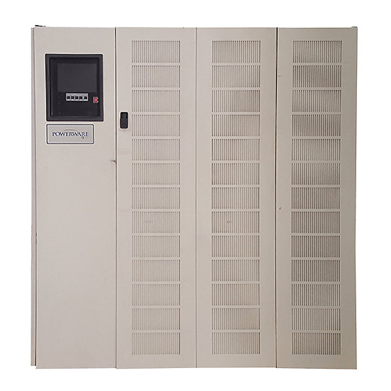
Powerware 9315 Installation And Operation Manual (180 pages)
Uninterruptible Power Supply 500 kVA -- 750 kVA
Brand:
Powerware
| Category:
UPS
| Size: 2 MB
Table of Contents
Installation and Operation
1
Important Safety Instructions
2
Save These Instructions
2
Table of Contents
3
List of Figures
8
Introduction
11
Basic System Configurations
12
Using this Manual
12
Getting Started 1
12
Installing the UPS 1
12
Conventions Used in this Manual
14
Safety Considerations
14
For more Information
15
Getting Help
15
Section I
17
Getting Started
19
Installing the UPS
19
Creating an Installation Plan
19
Preparing Your Site
19
Environment Considerations
20
Preparing for Wiring the UPS System
20
Inspecting and Unpacking each Cabinet
21
Installing the UPS System
23
Preliminary Installation Information
23
Single Module Installation
24
Installing the UPS Cabinet Sections
24
Installing UPS Internal Power and Control Wiring
24
Installing UPS External Power and Control Wiring
25
Installing Input/Rectifier Customer Connections
26
Installing Output/Inverter Customer Connections
26
Multi-Module Installation 2
27
Installing the UPS Cabinet Sections 2
27
Installing UPS Internal Power and Control Wiring 2
27
Prepare for Installing Optional Accessories
28
Installing UPS External Power and Control Wiring
28
Installing Input/Rectifier Customer Connections
28
Installing Output/Inverter Customer Connections
28
Initial Startup
29
Completing the Installation Checklist
29
Installation Checklist
30
Rev. D
31
Installing Batteries 3
33
Installing Batteries
34
Installing a Remote Battery Disconnect 4
35
Installation Notes
36
Table 4---1. Remote Battery Disconnect Power Terminations
37
Installation Procedures
39
Table 5---1. Remote Epo Wire Terminations
40
Table 5---2. Remote Epo
40
Installing a Remote Monitor Panel 6
41
To Install an Rmp
43
Table 6
44
Table 6---2. Rmp Wire Terminations
44
Table 7
47
Figure 8
51
Table 8
51
8 Installing a Supervisory Contact Module
55
Understanding UPS Operation
55
Looking Inside the Parallel Capacity/Redundant System
55
Normal, Battery, and Bypass Modes
56
Normal Mode
57
Bypass Mode
58
Battery Mode
59
10 Operational Controls and Features
61
General
61
UPS Standard Features
61
Control Panel
61
Figure 10
62
UPS Circuit Breakers
63
Emergency Upm off
63
Customer Interface
63
Automatic Battery Charge Current Limit
63
Customer Convenience Outlet
64
Installation Features
64
Options and Accessories
64
5% Input Filter
64
Battery
64
External Fused Battery Disconnect
64
Upgrade Capability
64
Remote Monitor Panel
64
Relay Interface Module
65
Modem
65
Safety Considerations
65
Symbols, Controls, and Indicators
66
Using the Control Panel
67
Description
67
Figure 11
67
Using the LCD Screen
68
Using the Pushbuttons
69
Adjusting the Contrast
69
Reading the Status Indicators
70
Using the Menu Options
71
System Meters Screen
72
Figure 11
72
Load Amp Meters Screen
73
Figure 11
73
Software Versions Screen
74
Figure 11
74
System History Screen
75
Figure 11
75
Active System Events Screen
76
Figure 11
76
Battery 10
77
Unit Statistics Screen
77
Figure 11
77
MIMIC Screen
78
Figure 11
78
Time Setup Screen
79
Figure 11
79
Port Setup Screen
80
UPS Operating Instructions
81
Starting the UPS
81
Starting the UPS in Bypass Mode
83
Transfer to Bypass Mode
83
Transfer to Normal Mode
83
Transfer to Bypass with UPS Shutdown
84
UPS and Critical Load Shutdown
84
Using the UPS EMERGENCY UPM off Pushbutton
84
To Use the UPS EMERGENCY UPM off Pushbutton
85
Using Features and Options
87
General
87
Building Alarm Monitoring
87
General Purpose Relay Contacts
87
Remote Monitor Panel
88
Figure 13
88
Table 13
88
Relay Interface Module
90
Supervisory Contact Module
91
Figure 13
91
Battery Racks
92
External Battery Disconnect
92
Responding to System Events
93
System Event Horns
93
System Event Lights
93
System Event Messages
94
Serial Communications
101
Locating the Communications Panel
101
Connecting Equipment to a Serial Port
101
Figure 15
102
Figure 15
103
Table 15---2. Pin Assignments for Port 2 (Db)
103
Figure 15
104
Configuring the Serial Ports
104
Table 15
105
Default Settings
106
Terminal Mode
107
Printing Selected Information
107
Entire Log (Ctrl + P)
108
Figure 15
109
Meters Printout (Ctrl + M)
109
System Information Printout (Ctrl + A)
109
System Configuration
110
System Configuration Mode Main Menu
110
Program Building Alarms
110
Enable/Disable Default Functions
111
Customize Alarm Messages
112
Program Unit Name
113
Change Password
113
Battery Test Setup
114
Modify Low Battery Time
115
Calibration Mode
115
Computer Mode
115
Remote Monitor Mode
115
Remote Notification
117
Remote Notification Features
118
Description of Operation
119
Call Answer
119
Call out
119
Hardware Requirements
121
Configuring the Modem
122
Basic Modem Configuration
122
Configuring the Modem to Call a Remote Computer
122
Configuring the Modem to Call a Numeric Pager
123
Final Modem Configuration
124
Ups Setup Configuration
125
User Selected Events
125
Maintaining the Ups System
129
Performing Preventive Maintenance
131
Maintenance Training
132
Product Specifications
133
Model Numbers
133
Ups System Input
133
Ups System Output
134
Environmental Specifications
135
Appendix A
137
Operation 12
152
Front View
161
Warranty
179
Rev. D
180
Advertisement
Powerware 9315 Operation Manual (92 pages)
200 kVA -- 300 kVA
Brand:
Powerware
| Category:
UPS
| Size: 0 MB
Table of Contents
Important Safety Instructions
2
Instructions Importantes Concernant la Sécurité
2
Table of Contents
3
List of Tables
8
1 Introduction
9
Using this Manual
9
For more Information
10
Getting Help
10
2 Getting Started
11
Figure 1. Typical Powerware Plus UPS System
11
Looking Inside the UPS
12
Figure 2. Main Elements of the UPS System
12
UPS Standard Features
13
Monitor Panel
13
Control Panel
13
Communication Panel
13
Computer Interface
13
Summary Alarm Contacts
13
Building Alarm Monitoring
13
Input Filter
13
Emergency Load off
13
Automatic Battery Charge Current Limit
13
Installation Features
14
Options and Accessories
14
Battery
14
External Battery Disconnect
14
Power Distribution Module
14
Upgrade Capability
14
Remote Monitor Panel
14
Relay Interface Module
14
Isolation Transformer
14
Modem
15
Customer Convenience Outlet
15
Safety Considerations
15
Symbols, Controls, and Indicators
16
3 Understanding UPS Operation
17
Normal Mode
18
Figure 3. Path of Current through the UPS in Normal Mode
18
Bypass Mode
19
Figure 4. Path of Current through the UPS in Bypass Mode
19
Battery Mode
20
Figure 5. Path of Current through the UPS in Battery Mode
20
Monitoring and Controlling UPS Operation
21
Figure 6. Location of the Monitor Panel and the Control Panel
21
4 Starting and Stopping the UPS
23
Using the Control Panel
23
Figure 7. UPS Control Panel
23
To Place the UPS in Normal Mode
24
To Shut down Power to the Critical Load While in Bypass Mode
25
To Shut down the UPS from Normal Mode
25
To Start the UPS in Bypass Mode
25
5 Using the Monitor Panel
27
Figure 8. UPS Monitor Panel
27
Using the LCD Screen
28
Figure 9. Parts of the LCD Screen
28
Using the Pushbuttons
29
Adjusting the Contrast
29
Using the Load off Pushbutton
29
Reading the Status Indicators
30
Using the Menu Options
31
Figure 10. System Meters Screen
31
Figure 11. Load Amps Meters Screen
32
Figure 12. Event History Log Screen
33
Figure 13. Active System Events Screen
34
Figure 14. Unit Statistics Screen
35
Figure 15. MIMIC Screen
36
Figure 16. Time Setup Screen
37
Figure 17. Port Setup Screen
38
6 Using Features and Options
39
Building Alarm Monitoring
39
Figure 18. External Connections for Building Alarm Monitoring
39
Summary Alarm Contacts
40
Figure 19. Summary Alarm Contacts
40
Remote Monitor Panel
41
Figure 20. Remote Monitor Panel
41
Battery Cabinets
43
External Battery Disconnect
43
Relay Interface Module
44
Figure 21. Relay Interface Module
44
Supervisory Contact Module
45
Figure 22. Supervisory Contact Module
45
7 Serial Communications
47
Locating the Communications Panel
48
Figure 23. Location of Communications Ports on the UPS
48
Connecting Equipment to a Serial Port
49
Figure 24. Port 1 Pin Assignments
49
Figure 25. Port 2 Pin Assignments
50
Configuring the Serial Ports
51
Figure 26. Setup Serial Port 1 Screen
51
Mode
52
Rate
52
Data/Stop
53
Default Settings
53
Disabled (no Handshaking)
53
Handshaking
53
Save
53
Xon/Xoff
53
Terminal Mode
54
Printing Selected Information
54
Entire Log (Ctrl + P)
55
Figure 27. Event History Log
55
Meters Printout (Ctrl + M)
56
System Information Printout (Ctrl + A)
56
Figure 28. System Meters
56
Rev. D
57
Battery Test Printout (Ctrl + B)
57
Uninterruptible Power System
57
Figure 29. Battery Test Log
57
System Configuration
58
System Configuration Mode Main Menu
58
Program Building Alarms
58
Enable/Disable Default Functions
59
Customize Alarm Messages
60
Program Unit Name
60
Adjust Output Voltage
61
Change Password
61
Battery Test Setup
62
Modify Low Battery Time
63
Calibration Mode
63
Computer Mode
63
Remote Monitor Mode
63
8 Remote Notification
65
Remote Notification Features
66
Description of Operation
67
Call Answer
67
Call out
67
Housekeeping
68
Hardware Requirements
69
Configuring the Modem
70
Basic Modem Configuration
70
Configuring the Modem to Call a Remote Computer
71
Configuring the Modem to Call a Numeric Pager
72
Configuring the Modem to Answer Incoming Calls
73
Final Modem Configuration
74
UPS Setup Configuration
75
User-Selected Events
76
9 Maintaining the UPS System
79
Important Safety Instructions
79
Performing Preventive Maintenance
81
Maintenance Training
81
10 Product Specifications
83
System Input
83
System Output
84
Powerware Plus
85
Environmental Specifications
85
Battery Specifications
85
Rev. D
85
11 Responding to System Events
87
System Event Horns
87
System Event Lights
87
System Event Messages
88
12 Using the LOAD off Pushbutton
91
To Use the LOAD off Pushbutton
91
Resetting the UPS System after Load off
91
Powerware 9315 Operation Manual (84 pages)
200–300 kVA
Brand:
Powerware
| Category:
UPS
| Size: 0 MB
Table of Contents
Save These Instructions
2
Table of Contents
3
1 Introduction
7
Conventions Used in this Manual
7
For more Information
8
Getting Help
8
2 Getting Started
9
Safety Warnings
9
Typical Powerware 9315 UPS System
10
Figure 2-1. Typical Powerware 9315 UPS System
10
Looking Inside the UPS
11
Figure 2-2. Main Elements of the UPS System
11
UPS Standard Features
12
Monitor Panel
12
Control Panel
12
Communication Bays
12
Input Filter
12
Emergency Load off
13
Automatic Battery Charge Current Limit
13
Installation Features
13
Options and Accessories
13
Battery
13
External Battery Disconnect
13
Power Distribution Module (LV Models Only)
14
Upgrade Capability
14
Remote Monitor Panel
14
Relay Interface Module
14
Input Isolation Transformer
14
5% Input Filter
14
Output Transformer
15
Modem
15
Customer Convenience Outlet
15
Symbols, Controls, and Indicators
16
3 Understanding UPS Operation
17
Normal Mode
17
Figure 3-1. Path of Current through the UPS in Normal Mode
18
Bypass Mode
19
Figure 3-2. Path of Current through the UPS in Bypass Mode
19
Battery Mode
20
Figure 3-3. Path of Current through the UPS in Battery Mode
20
Monitoring and Controlling UPS Operation
21
Figure 3-4. Location of the Monitor Panel and the Control Panel
21
4 Starting and Stopping the UPS
23
Using the Control Panel
23
Figure 4-1. UPS Control Panel
23
Resetting the UPS System after Load off
24
To Place the UPS in Normal Mode
24
To Shut down Power to the Critical Load While in Bypass Mode
25
To Shut down the UPS from Normal Mode
25
To Start the UPS in Bypass Mode
25
5 Using the Monitor Panel
27
Figure 5-1. UPS Monitor Panel
27
Using the LCD Screen
28
Figure 5-2. Parts of the LCD Screen (Typical for Powerware 9315 300 480/480V UPS)
28
Using the Buttons
29
Adjusting the Contrast
29
Using the Load off Button
29
Reading the Status Indicators
30
Using the Menu Options
30
Figure 5-3. System Meters Screen (Typical for Powerware 9315 300 480/480V UPS)
31
Figure 5-4. Load Amps Meters Screen
32
Figure 5-5. Event History Log Screen
33
Figure 5-6. Active System Events Screen
34
Figure 5-7. Unit Statistics Screen
35
Figure 5-8. MIMIC Screen
36
Figure 5-9. Time Setup Screen
37
Figure 5-10. Setup Serial Port 1 Screen
38
6 Using Features and Options
39
Figure 6-1. External Connections for Building Alarm Monitoring
39
Summary Alarm Contacts
40
Figure 6-2. Summary Alarm Contacts
40
Remote Monitor Panel
41
Figure 6-3. Remote Monitor Panel
41
Battery Cabinets
43
External Battery Disconnect
43
Relay Interface Module
44
Figure 6-4. Relay Interface Module
44
Figure 6-5. Supervisory Contact Module
45
7 Communication
47
Locating the Communication Bays
47
Slot Cards
48
Figure 7-1. Location of Communication Bays on the UPS (Powerware 9315 300)
48
Lansafe Power Management Software
49
Connecting Equipment to a Serial Port
49
Figure 7-2. Optional X−Slot Cards
49
Figure 7-3. Port 1 (DB−9) Pin Assignments
50
Figure 7-4. Port 2 (DB−25) Pin Assignments
50
Configuring the Serial Ports
52
Figure 7-5. Setup Serial Port 1 Screen
52
Mode
53
Rate
53
Data/Stop
54
Default Settings
54
Handshaking
54
Disabled (no Handshaking)
54
Xon/Xoff
54
Save
54
Terminal Mode
55
Printing Selected Information
55
Entire Log - [Ctrl]+[P]
56
Figure 7-6. Event History Log
56
Meters Printout - [Ctrl]+[M]
57
Figure 7-7. System Meters
57
System Information Printout - [Ctrl]+[A]
58
Battery Test Printout - [Ctrl]+[B]
58
Uninterruptible Power System
58
Figure 7-8. Battery Test Log
58
System Configuration
59
System Configuration Mode Main Menu
59
Program Building Alarms
59
Enable/Disable Default Functions
60
Customize Alarm Messages
61
Program Unit Name
62
Adjust Output Voltage
62
Change Password
62
Battery Test Setup
63
Modify Low Battery Time
64
Calibration Mode
64
Computer Mode
64
Remote Monitor Mode
64
Remote Notification
65
Important Safety Instructions
67
8 Maintaining the UPS System 8−1
67
Performing Preventive Maintenance
68
Maintenance Training
69
9 Product Specifications
71
10 Responding to System Events
75
System Event Horns
75
System Event Lights
75
System Event Messages
75
11 Using the LOAD off Button
79
Using the LOAD off Button
80
Resetting the UPS System after Load off
80
Warranty
81
Advertisement
Powerware 9315 Installation Manual (92 pages)
100 kVA -- 160 kVA
Brand:
Powerware
| Category:
UPS
| Size: 1 MB
Table of Contents
Save These Instructions
2
Table of Contents
3
1 Introduction
7
Figure 1. Typical UPS System
7
Using this Manual
8
Conventions Used in this Manual
9
For more Information
9
Getting Help
9
2 Getting Started
11
Preparing Your Site
12
Environment Considerations
12
Preparing for Wiring the UPS System
12
Inspecting and Unpacking each Cabinet
13
Figure 2. Cabinet as Shipped, with Outer Packaging and Pallet
13
Unloading the UPS Cabinet from the Pallet
14
Figure 3. Removing Front and Rear Supports
15
Creating an Installation Plan
16
3 Installing the UPS
17
Preparing the UPS for Installing
19
Optional Cabinets or Accessories
19
Figure 5. Preparing the UPS for Installing Other Cabinets
20
Completing the Installation Checklist
21
Installation Checklist
22
Notes
23
4 Joining Cabinets
25
Figure 6. Methods of Joining Cabinets
25
Figure 7. Joining an Optional Cabinet to the UPS
26
Figure 8. Pushing Cabinets Together
26
Method a
26
Figure 9. Placement of Joining Brackets
27
Figure 10. Installing the Angled Bracket
28
Figure 11. Preparing to Join Component Cabinets
29
Method B
29
Figure 12. Joining Component Cabinets
30
Grounding Joined Cabinets
31
Method a Grounding
31
Method B Grounding
31
5 Installing Battery Cabinets
33
Two Models Are Available
33
Important Safety Instructions
33
General Notes about Installing Battery Cabinets and Remote Disconnects
34
Figure 15. Input Transformer Cabinet
35
Figure 16. Installing an Input Transformer Cabinet
37
Figure 17. Typical PDM Cabinet
39
Figure 18. Remote EPO Control
41
Figure 19. Remote Battery Disconnect Enclosure
43
Installing a Remote Monitor Panel
45
Figure 20. Remote Monitor Panel (RMP)
46
Figure 21. Terminal Block Bracket
47
Figure 22. Wiring an RMP to the UPS
48
Figure 23. Relay Interface Module
51
Figure 24. Terminal Block Bracket
52
Figure 25. Wiring an RIM to the UPS
52
Figure 26. Supervisory Contact Module
55
Figure 27. Terminal Block Bracket
56
Figure 28. Wiring an SCM to the UPS
56
Figure 29. Supervisory Contact Module TB2
58
Figure 4. UPS Cabinet
69
Powerware 9315 Installation Addendum (74 pages)
Uninterruptible Power Supply 500 kVA -- 750 kVA
Brand:
Powerware
| Category:
Power Supply
| Size: 1 MB
Table of Contents
Table of Contents
3
Introduction
7
Using this Manual
8
Conventions Used in this Manual
8
Safety Considerations
9
For more Information
10
Getting Help
10
Getting Started
11
Required Tools and Equipment
11
Removal and Installation Guidelines
12
Preliminary Operational Checks
12
Removing Transformer T1
13
Transformer T1 Removal
13
Hardware Removal for Access to T1
13
Disconnecting T1 Power Wiring
14
Removing T1
20
Assembly and Hardware Reinstallation
21
Removing Transformer T3
23
Transformer T3 Removal
23
Hardware Removal for Access to T3
23
Disconnecting T3 Power Wiring
24
Removing T3
31
Assembly and Hardware Reinstallation
32
Installing Transformer T1
35
Inspecting and Unpacking T1
35
Transformer T1 Installation
36
Hardware Removal for Access to T1 Mounting Location
36
Installing T1
43
Reconnecting T1 Power Wiring
44
Assembly and Hardware Reinstallation
47
Installing Transformer T3
49
Inspecting and Unpacking T3
49
Transformer T3 Installation
50
Hardware Removal for Access to T3 Mounting Location
50
Installing T3
58
Reconnecting T3 Power Wiring
58
Assembly and Hardware Reinstallation
61
Dielectric Testing
63
Dielectric Test Procedure after Transformer Replacement
63
Equipment
63
UUT Preparation
63
Single Module (RT) Preparation
63
Installing UPS Internal Power and Control Wiring
63
Single Module (RT) Test Setup
65
Multi-Module Preparation
67
Installing UPS Internal Power and Control Wiring
67
Dielectric Testing
69
Definitions
69
Testing
69
Returning System to Normal
70
Single Module (RT)
70
Multi-Module Installation
70
Final Assembly
73
Output/Inverter Cabinet
73
Input/Rectifier Cabinet
73
Powerware 9315 Installation & Operation Manual (54 pages)
Parallel Redundant Uninterruptible Power Supply
Brand:
Powerware
| Category:
UPS
| Size: 0 MB
Table of Contents
Important Safety Instructions
2
Save These Instructions
2
Table of Contents
3
Figure 1. Typical Parallel Cabinet
7
Using this Manual
8
For more Information
9
Getting Help
9
Introduction
7
Section I Installation
11
1 Getting Started
13
Figure 2. Front and Side View of Parallel Cabinet
13
Preparing the Site
14
Environment Considerations
15
Preparing for Wiring the Parallel Redundant System
15
Inspecting and Unpacking the Parallel Cabinet
16
Figure 3. Cabinet as Shipped, with Outer Packaging and Pallet
16
Unloading the Parallel Cabinet from the Pallet
17
Figure 4. Removing Front and Rear Supports
18
Creating an Installation Plan
19
2 Installing the Parallel Redundant System
21
Figure 5. Top, Bottom, and Front View of Parallel Cabinet
21
And Common Batteries
23
Parallel Redundant Modules with Separate Batteries
24
Figure 7. Modules with Separate Batteries
24
Parallel Redundant Modules with Common Battery
26
Figure 8. Modules with Common Battery
26
Power Wiring Details
28
Control Wiring Interconnect Details
29
Figure 9. Grouping for Twisting Requirements
29
3 Parallel Redundantmodules with Separate Batterie S
23
Section II Operation
31
4 Getting Started
33
Parallel Redundant System Description
34
Figure 10. Controls and Indicators
35
Looking Inside the Parallel Redundant System
36
Safety Considerations
37
Symbols, Controls, and Indicators
38
5 Understanding Parallel Redundant Operation
39
Normal, Battery, and Bypass Modes with Parallel Operation
40
6 Operating Instructions for the Parallel
41
Redundant System
41
Module Output Breakers (Mobs)
41
How to Open and Close the MOB
41
Starting and Stopping Using Parallel Redundant System
41
How to Isolate a Module
42
Shut down a Module
42
Transfer System to Bypass
42
Load off
43
Figure 11 UPS Outputs and Communications
45
Figure 12 Mechanical Details
45
Figure 13 Electrical Access Details
45
Appendix A
45
Powerware 9315 Installation & Operation Manual (53 pages)
fixed master sync control
Brand:
Powerware
| Category:
UPS
| Size: 1 MB
Table of Contents
Important Safety Instructions
2
Save These Instructions
2
Table of Contents
3
Figure 1. Powerware Fixed Master Sync Control
5
For more Information
6
Using this Manual
6
Getting Help
7
Introduction
5
1 Getting Started
9
Preparing the Site
9
Creating an Installation Plan
9
Environmental Considerations
10
Preparing for Wiring the Powerware Fixed Master Sync Control
10
Inspecting and Unpacking the Powerware Fixed Master Sync Control
10
2 Installing the Powerware Sync Control
11
Figure 2. Powerware Fixed Master Sync Control Interface Location for
12
Figure 3. Powerware Fixed Master Sync Control Interface Location for 100
13
Figure 4. Powerware Fixed Master Sync Control Interface Locations for
14
Figure 5. Powerware Fixed Master Sync Control Interface Location for
15
Figure 6. Powerware Fixed Master Sync Control Interface Location for 750 Kva Single Module Powerware 9315 UPS System
16
Figure 7. Powerware Fixed Master Sync Control Interface Location for Fpowerware Hot Sync
17
Figure 8. Powerware Fixed Master Sync Control Interface Location for Powerware Hot Sync
18
Figure 9. Location of (S)SBM Customer Interface Panel Terminal Blocks TB3, TB4, TB6 and TB7
19
Figure 10. Typical Control Wiring Termination Locations for the Powerware Fixed Master Sync Control
20
3 Powerware Fixed Master Sync Control Operation
21
Powerware Fixed Master Sync Control
21
Understanding Fixed Master Sync Control Operation
22
Figure 11. Powerware Fixed Master Sync Control Block Diagram for a
22
Powerware Hot Sync
22
Operation
24
Figure 12. Synchronization Reference Control
24
Figure 13. Powerware Fixed Master Sync Control Controls and Indicators
25
Customer Monitoring
26
Maintenance Operations
27
Appendix A
29
Powerware 9315 Installation & Operation Manual (48 pages)
Maintenance Bypass Module 30--160kVA
Brand:
Powerware
| Category:
Power Supply
| Size: 0 MB
Table of Contents
Maintenance Bypass
1
Table of Contents
3
List of Figures
4
1 Introduction
5
Figure 1. Typical 30
5
Using this Manual
6
Conventions Used in this Manual
6
For more Information
7
Getting Help
7
2 Getting Started
9
Figure 2. Front and Side View of Typical Maintenance Bypass
9
Preparing the Site
10
Creating an Installation Plan
10
Environmental Considerations
10
Preparing for Wiring the Maintenance Bypass Module
10
Inspecting and Unpacking the Maintenance Bypass Module
11
Figure 3. MBM as Shipped, with Outer Packaging and Pallet
11
Unloading the MBM from the Pallet
13
Figure 4. Detail of Shipping Supports
14
3 Installing and Wiring the Maintenance Bypass Module
15
Figure 5. Top, Bottom, and Front View of Maintenance Bypass Module
15
Line and Load Wiring
17
4 Maintenance Bypass Module Operation
19
Preliminary Checks and Startup for UPS Equipped with
19
Maintenance Bypass Module
19
MBM Operation Without Kirk Key Interlocks
20
MBM Operation with Kirk Key Interlocks (Optional)
21
Kirk Key Solenoid Release Unit (SKRU)
21
MBM Transfer Sequences
21
Appendix A
23
Maintenance
23
Short Circuits
23
Maintenance Bypass Module Diagrams
23
Appendix A
25
Advertisement
Related Products
Powerware 9120
Powerware 9125
Powerware 9155
Powerware 9150
Powerware Prestige series 9
Powerware 9350
Powerware 9355
Powerware 9335
Powerware 9315s
Powerware 9330
Powerware Categories
UPS
Power Supply
Surge Protector
Adapter
Chassis
More Powerware Manuals
Login
Sign In
OR
Sign in with Facebook
Sign in with Google
Upload manual
Upload from disk
Upload from URL