Powerware 9315 Installation & Operation Manual
Parallel redundant uninterruptible power supply
Hide thumbs
Also See for 9315:
- Operation manual (92 pages) ,
- Installation manual (92 pages) ,
- Installation addendum (74 pages)

Related Manuals for Powerware 9315


Summary of Contents for Powerware 9315
- Page 1 Parallel Redundant Uninterruptible Power Supply Installation/Operation Manual 164202013 Rev. D...
-
Page 2: Important Safety Instructions
WARNING: This is a product for restricted sales distribution to informed partners. Installation restrictions or additional measures may be needed to prevent disturbances. Powerware 9315 Parallel Redundant System I & O 164202013, Rev. D 041599... -
Page 3: Table Of Contents
......Powerware 9315 Parallel Redundant System I & O 164202013 Rev. D 041599... - Page 4 ..........A---1 Powerware 9315 Parallel Redundant System I & O 164202013, Rev. D 041599...
- Page 5 ....... . A---4 Powerware 9315 Parallel Redundant System I & O 164202013 Rev. D 041599...
- Page 6 This Page Intentionally Left Blank. Powerware 9315 Parallel Redundant System I & O 164202013, Rev. D 041599...
-
Page 7: Introduction
UPS system when in parallel. For full installation and operation of the UPS system and battery installation, refer to the PowerwareÒ 9315 Installation, PowerwareÒ 9315 Operation, and the PowerwareÒ Series 685 and 1085 Auxiliary Battery Cabinets Installation manuals provided with the UPS system and battery cabinet accessory. -
Page 8: Using This Manual
Using This Manual This manual contains installation and operation procedures for the PowerwareÒ 9315 Parallel Redundant system. In this manual, parallel redundant system refers to the parallel cabinet, its internal components, and those components of the UPS modules that assist in parallel redundant operation. The text uses these conventions: ·... -
Page 9: For More Information
Contact the local Powerware Field Service office for information on how to obtain copies of these manuals. Getting Help If you have a question about any of the information in this manual, or if you have a... - Page 10 This Page Intentionally Left Blank. Powerware 9315 Parallel Redundant System I & O 164202013, Rev. D 041599...
-
Page 11: Section I Installation
Section I Installation Powerware 9315 Parallel Redundant System I & O 164202013 Rev. D 041599... - Page 12 This Page Intentionally Left Blank. Powerware 9315 Parallel Redundant System I & O 164202013, Rev. D 041599...
-
Page 13: Getting Started
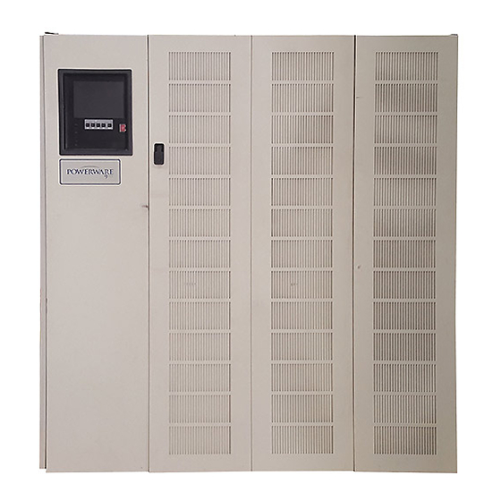
Figure 2 shows the front and side view of the parallel cabinet. Figure 2. Front and Side View of Parallel Cabinet Powerware 9315 Parallel Redundant System I & O 164202013 Rev. D 041599... -
Page 14: Preparing The Site
PowerwareÒ 9315 Operation manual provided with the UPS system. The operating environment must meet the size and weight requirements supplied in the PowerwareÒ 9315 Installation manual provided with the UPS system. If the parallel redundant system is to be operated at an altitude higher than 1500 meters (5000 feet), contact the local sales or service office for important information about high altitude operation. -
Page 15: Environment Considerations
UPS. For UPS external wiring requirements, including minimum AWG size of external wiring, see the PowerwareÒ 9315 Installation manual provided with the UPS system. NOTE: Material and labor for external wiring are to be provided by designated personnel. -
Page 16: Inspecting And Unpacking The Parallel Cabinet
Insert the forklift jacks between the foam cushions on the bottom of the unit. CAUTION: Do not tilt cabinet more than 10 degrees from vertical. Powerware 9315 Parallel Redundant System I & O 164202013, Rev. D 041599... -
Page 17: Unloading The Parallel Cabinet From The Pallet
After the foam cushions clear the floor, remove the hardware loosened in step 3. Pull the foam cushions out from under the cabinet, and discard or recycle them in a responsible manner. Powerware 9315 Parallel Redundant System I & O 164202013 Rev. D 041599... -
Page 18: Figure 4. Removing Front And Rear Supports
Discard or recycle the hardware and support brackets in a responsible manner. Install the doors removed in step 1. The parallel cabinet is now ready to be rolled to its final location. Powerware 9315 Parallel Redundant System I & O 164202013, Rev. D 041599... -
Page 19: Creating An Installation Plan
Before beginning to install the parallel cabinet, read and understand how this manual applies to the system being installed. It is important to note that UPS module installation procedures are contained in the PowerwareÒ 9315 Installation manual provided with the UPS system. It is recommended to first understand how to install the UPS modules. - Page 20 This Page Intentionally Left Blank. Powerware 9315 Parallel Redundant System I & O 164202013, Rev. D 041599...
-
Page 21: Installing The Parallel Redundant System
Cooling Grate (Cooling Air Outlets) Wire Entry Cable Entry, Top View Bottom Wire Entry Cable Entry, Floor Plan View Figure 5. Top, Bottom, and Front View of Parallel Cabinet Powerware 9315 Parallel Redundant System I & O 164202013 Rev. D 041599... - Page 22 Control Wiring Interconnect Details in Chapter 3 of this manual. Figure 6 shows typical control wiring and power wiring terminations of the UPS module and parallel cabinet. Refer to the Powerware 9315 Installation manual provided with the UPS system for location of UPS module cabinet wiring terminations.
-
Page 23: And Common Batteries
Determine which battery configuration is being utilized before beginning installation. If battery cabinets and remote disconnects provided by Powerware Corporation are being installed, refer to the Powerware Series 685 and 1085 Auxiliary Battery Cabinets Installation manual, 164200300, for instructions on installation. -
Page 24: Parallel Redundant Modules With Separate Batteries
Figure 7 shows a diagram of the parallel redundant system with UPS modules utilizing separate battery cabinets. NOTE: Refer to Powerware 9315 Installation manual provided with the UPS system for battery shunt trip connections. Battery... - Page 25 Figure 13 in Appendix A of this manual. For the UPS Module connections, please refer to the PowerwareÒ 9315 Installation manual provided with the UPS system for protection and wiring requirements and recommendations.
-
Page 26: Parallel Redundant Modules With Common Battery
NOTE: UPS modules sharing a battery cabinet(s) must utilize a remote battery cabinet(s). Refer to the Powerware Series 685 and 1085 Auxiliary Battery Cabinets Installation manual 164200300, for instructions on installation. Refer to Powerware 9315 Installation manual provided with the UPS System for battery breaker shunt trip connections. Battery... - Page 27 For the D connection, make sure input feeds originate from the same power source. Means for separate isolation (circuit breaker or disconnect) are recommended. Refer to the PowerwareÒ 9315 Installation manual provided with the UPS system for input feeds to the UPS module.
-
Page 28: Power Wiring Details
100%. The neutral bus (terminal strip E12) contains sufficient cable landing to wire double-size neutrals if needed. NOTE: Material and labor for external wiring are to be provided by designated personnel. Powerware 9315 Parallel Redundant System I & O 164202013, Rev. D 041599... -
Page 29: Control Wiring Interconnect Details
Control wiring should be twisted pairs and twisted triple as shown in Figure 9. Parallel Module 1 Cabinet (or 2) MOB#1 (#2) Indicates grouping for twisting requirements. Figure 9. Grouping for Twisting Requirements Powerware 9315 Parallel Redundant System I & O 164202013 Rev. D 041599... - Page 30 This Page Intentionally Left Blank. Powerware 9315 Parallel Redundant System I & O 164202013, Rev. D 041599...
-
Page 31: Section Ii Operation
Section II Operation Powerware 9315 Parallel Redundant System I & O 164202013 Rev. D 041599... - Page 32 This Page Intentionally Left Blank. Powerware 9315 Parallel Redundant System I & O 164202013, Rev. D 041599...
-
Page 33: Getting Started
With the PowerwareÒ 9315 Parallel Redundant system, when one UPS module is taken off line or becomes disabled, the redundant module continues working with the building’s electrical system to supply clean, consistent power that sensitive... -
Page 34: Parallel Redundant System Description
The parallel cabinet also includes associated terminal strips for making the power and control connections to UPS modules. Figure 10 shows the controls and indicators of the parallel cabinet. Powerware 9315 Parallel Redundant System I & O 164202013, Rev. D 041599... -
Page 35: Figure 10. Controls And Indicators
MODULE MODULE OUTPUT OUTPUT BREAKER 1 BREAKER 2 (MOB 1) (MOB 2) Figure 10. Controls and Indicators Powerware 9315 Parallel Redundant System I & O 164202013 Rev. D 041599... -
Page 36: Looking Inside The Parallel Redundant System
(such as a generator) or shut down the critical load in an orderly manner. Refer to the PowerwareÒ 9315 Operation manual provided with the UPS system for operation of the UPS. -
Page 37: Safety Considerations
The system is not intended for outdoor use. · The operating environment should be maintained within the parameters stated in this manual and the Powerware 9315 Operation manual provided with the UPS system. · Keep the cabinet doors closed to ensure proper cooling airflow and to protect personnel from dangerous voltages inside the unit. -
Page 38: Symbols, Controls, And Indicators
Stop and refer to the Operator’s Manual for more information. RISK OF ELECTRIC SHOCK There is a risk of electric shock present, and you should observe associated warnings. The equipment contains high voltages. Powerware 9315 Parallel Redundant System I & O 164202013, Rev. D 041599... -
Page 39: Understanding Parallel Redundant Operation
· In Normal mode, the UPS system functions normally as described in the PowerwareR 9315 Operation manual provided with the UPS system. In the parallel redundant system, power leaves the UPS module from its AC output and is routed into the designated MOB in the parallel cabinet. As the system is in Normal mode, the MOBs are closed and clean power is routed directly to the AC output of the parallel cabinet and then to supply the critical load. -
Page 40: Normal, Battery, And Bypass Modes With Parallel Operation
UPS system operation. The only difference is that the critical bus in the parallel cabinet is the AC output. See the PowerwareÒ 9315 Operation manual provided with the UPS system for details on Battery mode of operation. -
Page 41: Operating Instructions For The Parallel
Start each module as described for normal UPS system startup in the PowerwareÒ 9315 Operation manual provided with the UPS system. If the MOBs have been opened, they should only be closed when the OK TO CLOSE lamp is illuminated. -
Page 42: How To Isolate A Module
When a module’s designated MOB is open, it will work like a standard Reverse Transfer module as described in the PowerwareÒ 9315 Operation manual provided with the UPS system. The MOB should only be closed when its OK TO CLOSE lamp is illuminated. -
Page 43: Load Off
The LOAD OFF pushbutton (referred to as the emergency power off) only interrupts the ability of a single module to deliver power to the critical bus. The redundant module will continue to support the critical load. Refer to the Powerware 9315 Operation manual for details on the LOAD OFF pushbutton. - Page 44 This Page Intentionally Left Blank. Powerware 9315 Parallel Redundant System I & O 164202013, Rev. D 041599...
-
Page 45: Figure 11 Ups Outputs And Communications
Table A---2 UPS Power Cable Terminations and Connection Points · Table A---3 Tie Cabinet Power Inputs and Termination Requirements · Table A---4 Power Output Termination Requirements Powerware 9315 Parallel Redundant System I & O A ---1 164202013 Rev. D 041599... - Page 46 SIDE PANEL MOUNTING SCREWS LEVELING FEET COMMUNICATION TERMINAL STRIP PANEL NOTE: 100---160 KVA UPS Shown with Right Door Open or Removed Figure 11. UPS Outputs and Communications Powerware 9315 Parallel Redundant System I & O A ---2 164202013, Rev. D 041599...
- Page 47 PARALLEL TIE CABINET FRONT VIEW SIDE VIEW Dimensions are in millimeters (inches) Cabinet Weight: 260 kg (570 lb) Cooling Requirements: Convection Heat Rejection: Figure 12. Mechanical Details Powerware 9315 Parallel Redundant System I & O A ---3 164202013 Rev. D 041599...
-
Page 48: Rev. D
Overall width dimensions include side panels. Location of TB3 Subtract 25 mm (1 in) for each side panel for in UPS Modules line up and match. Figure 13. Electrical Access Details Powerware 9315 Parallel Redundant System I & O A ---4 164202013, Rev. D 041599... - Page 49 Refer to the applicable Powerware 9315 Refer to the applicable Powerware 9315 Phase C UPS installation manual for this information UPS installation manual for this information Neutral/ Powerware 9315 Parallel Redundant System I & O A ---5 164202013 Rev. D 041599...
- Page 50 B, C #3--#1, (200) #1/0-350 kcmil, (250) 250 kcmil E9, E10, Phase A, #8-350 kcmil #8--#4, (150) 5/16 B, C #3--#1, (200) #1/0-350 kcmil, (250) continued Powerware 9315 Parallel Redundant System I & O A ---6 164202013, Rev. D 041599...
- Page 51 (1) #6-600 #8-#3, (275) kcmil (2) 250 E9, E10, Phase A, (2) #2/0-400 #2-600 kcmil, kcmil B, C kcmil or (375) (1) #6-600 #8-#3, (275) kcmil continued Powerware 9315 Parallel Redundant System I & O A ---7 164202013 Rev. D 041599...
- Page 52 Power wiring size recommendation is copper wire rated at 75_C for Powerware 9315 models 40 through 300 and 90_C the Powerware 9315 400 and 500. If the wire is run in ambient temperature higher than 30_C, larger size and/or higher temperature wire is necessary.
- Page 53 External overcurrent protection is not provided by this product, but is required by codes. Refer to Tables A---3 and A---4 for power wiring recommendations and requirements for the parallel cabinet. Refer to the PowerwareÒ 9315 Installation manual provided with the UPS system for UPS module power wiring requirements.
- Page 54 This Page Intentionally Left Blank. Powerware 9315 Parallel Redundant System I & O A ---10 164202013, Rev. D 041599...
Need help?
Do you have a question about the 9315 and is the answer not in the manual?
Questions and answers