Powerware 9155 User Manual
8-15 kva
Hide thumbs
Also See for 9155:
- Product catalog (24 pages) ,
- Technical specifications (10 pages) ,
- User manual (66 pages)
Table of Contents
Advertisement
Quick Links
Advertisement
Table of Contents

Related Manuals for Powerware 9155


Summary of Contents for Powerware 9155
- Page 1 9155 USER’S GUIDE 8–15 kVA www.powerware.com...
- Page 2 VCCI Notice Powerware, ABM, and FERRUPS are registered trademarks and X-Slot, ConnectUPS, and Powerware Hot Sync are trademarks of Eaton Power Quality Corporation. Greenlee is a registered trademark of Greenlee Textron. Modbus is a registered trademark of Modicon.
- Page 3 Requesting a Declaration of Conformity Units that are labeled with a CE mark comply with the following harmonized standards and EU directives: Harmonized Standards: IEC 62040-1-1 and IEC 62040-2; IEC 60950 Third Edition EU Directives: 73/23/EEC, Council Directive on equipment designed for use within certain voltage limits 93/68/EEC, Amending Directive 73/23/EEC 89/336/EEC, Council Directive relating to electromagnetic compatibility...
-
Page 4: Special Symbols
Special Symbols The following are examples of symbols used on the UPS to alert you to important information: RISK OF ELECTRIC SHOCK - Indicates that a risk of electric shock is present and the associated warning should be observed. CAUTION: REFER TO OPERATOR’S MANUAL - Refer to your operator’s manual for additional information, such as important operating and maintenance instructions. -
Page 5: Table Of Contents
........Powerware 9155 UPS (8–15 kVA) User’s Guide 164201553 Rev D www.powerware.com... - Page 6 ..........Powerware 9155 UPS (8–15 kVA) User’s Guide 164201553 Rev D www.powerware.com...
-
Page 7: Introduction
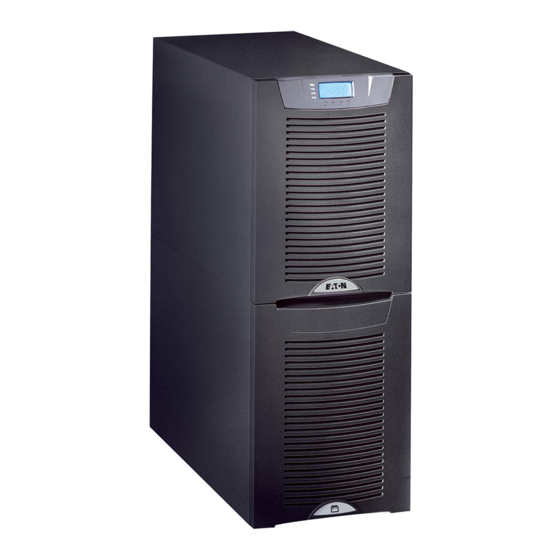
With the Powerware 9155, you can safely eliminate the effects of electrical line disturbances and guard the integrity of your systems and equipment. Figure 1 shows the Powerware 9155 UPS and an optional Extended Battery Module (EBM). - Page 8 More wattage in less space with a 0.9 power factor – protecting more equipment and leaving more room for expansion. Support for Powerware Hot Sync t paralleling of multiple modules for redundancy or extra capacity. Input current total harmonic distortion (THD) of less than five percent, using active input power factor correction.
- Page 9 The parallel system consists of two to three UPSs, each with a parallel CAN Bridge Card, and a parallel tie cabinet. Refer to the Powerware 9155 Parallel UPS (8–15 kVA) User’s Guide for more information. Input Isolation Transformer The optional input isolation transformer is located at the bottom of a 3-high UPS model.
- Page 10 Introduction Powerware 9155 UPS (8–15 kVA) User’s Guide 164201553 Rev D www.powerware.com ®...
-
Page 11: Safety Warnings
To reduce the risk of fire, connect only to a circuit provided with 100 amperes maximum branch circuit overcurrent protection in accordance with the National Electrical Code, ANSI/NFPA 70. Output overcurrent protection and disconnect switch must be provided by others. Powerware 9155 UPS (8–15 kVA) User’s Guide 164201553 Rev D www.powerware.com ®... - Page 12 être fournie par un autre fournisseur. Les interrupteurs de déconnexion convenables pour le(s) circuit(s) de sortie de courant alternatif doivent être fournie par un autre fournisseur. Powerware 9155 UPS (8–15 kVA) User’s Guide 164201553 Rev D www.powerware.com ®...
-
Page 13: Advertencias De Seguridad
La protección contra exceso de corriente para el/los circuito(s) de CA de salida será suministrada por terceros. Los interruptores de desconexión debidamente clasificados para el/los circuito(s) de CA de salida serán suministrados por terceros. Powerware 9155 UPS (8–15 kVA) User’s Guide 164201553 Rev D www.powerware.com ®... - Page 14 Es necesario desechar las baterías de un modo adecuado. Consulte las normas locales para conocer los requisitos pertinentes. Nunca deseche las baterías en el fuego. Las baterías pueden explotar si se las expone a la llama. Powerware 9155 UPS (8–15 kVA) User’s Guide 164201553 Rev D www.powerware.com ®...
-
Page 15: Ups Setup
Check the battery recharge date on the packaging label. If the date has expired and the batteries were never recharged, do not use the UPS. Contact your service representative. Powerware 9155 UPS (8–15 kVA) User’s Guide 164201553 Rev D www.powerware.com ®... -
Page 16: Floor Loading
Isolation Transformer 2-High EBM 3-High EBM Clearances The following clearances are recommended for the Powerware 9155 UPS: From Front of Cabinet 36” (91.4 cm) working space From Back of Cabinet 6” (15.2 cm) without MBM/PDM installed; with MBM/PDM installed, clearance determined by... -
Page 17: Unloading The Cabinet(S)
To remove the UPS or EBM from the shipping pallet: 1. Remove the two M10 bolts securing the stabilizing bracket to the pallet (see Figure 2). M10 bolts Figure 2. Removing the Stabilizing Bracket Bolts Powerware 9155 UPS (8–15 kVA) User’s Guide 164201553 Rev D www.powerware.com ®... - Page 18 (see Figure 3). Front Shipping Bracket M10 Bolts Stabilizing Bracket M10 Bolts M4 Screws Shipping Pad Figure 3. Removing the Brackets and Shipping Pad Powerware 9155 UPS (8–15 kVA) User’s Guide 164201553 Rev D www.powerware.com ®...
- Page 19 (see Figure 4). If needed, adjust the leveling feet so that the cabinet will roll. 6. Roll the cabinet to the desired location. Figure 4. Unloading the Cabinet Powerware 9155 UPS (8–15 kVA) User’s Guide 164201553 Rev D www.powerware.com ®...
-
Page 20: Selecting An Installation Option
UPS Setup Selecting an Installation Option You are now ready to install the Powerware 9155 UPS. Select one of the following installation options according to your UPS configuration: UPS Configuration Installation Chapter UPS only Chapter 4, “UPS Only Installation” on page 15 UPS with an optional input isolation Chapter 5, “Input Isolation Transformer Installation”... -
Page 21: Ups Only Installation
Chapter 4 UPS Only Installation The Powerware 9155 has the following power connections: 2-phase (L1 and L2), neutral, and ground connection for rectifier/bypass input 2-phase (L1 and L2), neutral, and ground connection for load output The nominal input/output voltages are: 100/200, 110/220, or 120/240 Vac with 180°... - Page 22 NOTE To accommodate the feature of easy system expandability, it is recommended that initial installation of the Powerware 9155 UPS contain wiring to support the maximum capacity of the UPS cabinet. 3. Switch off utility power to the distribution point where the UPS will be connected.
- Page 23 7. Hardwire the input (TB1-1 through TB1-5) and output (TB1-6 through TB1-9) terminations for the UPS. See Table 2 for specifications and Figure 6 for a detailed view of the UPS terminal block. Powerware 9155 UPS (8–15 kVA) User’s Guide 164201553 Rev D www.powerware.com ®...
- Page 24 Input Output Figure 6. UPS Terminal Block 8. Replace the UPS wiring access cover. 9. Continue to “Stabilizing the Cabinet” on page 49 to complete the UPS installation. Powerware 9155 UPS (8–15 kVA) User’s Guide 164201553 Rev D www.powerware.com ®...
- Page 25 UPS Only Installation Figure 7. UPS Only Wiring Diagram Powerware 9155 UPS (8–15 kVA) User’s Guide 164201553 Rev D www.powerware.com ®...
- Page 26 UPS Only Installation Powerware 9155 UPS (8–15 kVA) User’s Guide 164201553 Rev D www.powerware.com ®...
-
Page 27: Input Isolation Transformer Installation
Chapter 5 Input Isolation Transformer Installation The Powerware 9155 has the following power connections: 2-phase (L1 and L2), neutral, and ground connection for rectifier/bypass input 2-phase (L1 and L2), neutral, and ground connection for load output C A U T I O N The input isolation transformer output is always 240V (180°... - Page 28 NOTE To accommodate the feature of easy system expandability, it is recommended that initial installation of the Powerware 9155 UPS contain wiring to support the maximum capacity of the UPS cabinet. 3. Switch off utility power to the distribution point where the UPS will be connected.
- Page 29 11. Hardwire the input, output, and ground terminations for the input isolation transformer. See Table 4 for specifications and Figure 9 for a detailed view of the input isolation transformer terminal block. Powerware 9155 UPS (8–15 kVA) User’s Guide 164201553 Rev D www.powerware.com ®...
- Page 30 Input Isolation Transformer Installation Output Input Edge Grommet Pilot Holes in Conduit Landing Figure 9. Input Isolation Transformer Hardwiring Powerware 9155 UPS (8–15 kVA) User’s Guide 164201553 Rev D www.powerware.com ®...
- Page 31 TB1-8 3 AWG Ground TB1-9 8 AWG *Use only 90°C-rated copper wire. Minimum wire size is based on 120/208 full load ratings applied to NEC Code Table 310-16. Powerware 9155 UPS (8–15 kVA) User’s Guide 164201553 Rev D www.powerware.com ®...
- Page 32 Insert the supplied nylon bushing inside the wiring access hole. 19. Continue to the following chapter, “UPS-Mounted Bypass Switch Installation,” to complete the installation. Powerware 9155 UPS (8–15 kVA) User’s Guide 164201553 Rev D www.powerware.com ®...
- Page 33 Input Isolation Transformer Installation Figure 11. UPS with Input Isolation Transformer Wiring Diagram Powerware 9155 UPS (8–15 kVA) User’s Guide 164201553 Rev D www.powerware.com ®...
- Page 34 Input Isolation Transformer Installation Figure 12. UPS with Input Isolation Transformer and MBM/PDM Wiring Diagram Powerware 9155 UPS (8–15 kVA) User’s Guide 164201553 Rev D www.powerware.com ®...
-
Page 35: Ups-Mounted Bypass Switch Installation
2. Remove the lowest top cover screw on each side of the UPS and discard. Lowest Top Cover Screw (one each side) Connecting Plate (8 screws) Figure 13. UPS Rear View (2-High Cabinet Shown) Powerware 9155 UPS (8–15 kVA) User’s Guide 164201553 Rev D www.powerware.com ®... - Page 36 Figure 14). Repeat for the other side. 4. Remove the UPS wiring access cover and retain. UPS Wiring Access Cover L-Bracket and Screws Figure 14. Attaching the L-Brackets Powerware 9155 UPS (8–15 kVA) User’s Guide 164201553 Rev D www.powerware.com ®...
- Page 37 UPS Electronics Unit Nylon Bushings in UPS Wiring Access Holes MBM/PDM Wiring Access Cover and the Conduit Landing Plate (Removed) Figure 15. Installing the MBM or PDM (MBM Shown) Powerware 9155 UPS (8–15 kVA) User’s Guide 164201553 Rev D www.powerware.com ®...
-
Page 38: Wiring The Mbm/Pdm
Screws to L-Bracket Figure 16. Attaching the L-Brackets Wiring the MBM/PDM The Powerware 9155 UPS has the following power connections: 2-phase (L1 and L2), neutral, and ground connection for rectifier/bypass input 2-phase (L1 and L2), neutral, and ground connection for load output The nominal input/output voltages are: 100/200, 110/220, or 120/240 Vac with 180°... - Page 39 NOTE To accommodate the feature of easy system expandability, it is recommended that initial installation of the Powerware 9155 UPS contain wiring to support the maximum capacity of the UPS cabinet. 3. Switch off utility power to the distribution point where the UPS will be connected.
- Page 40 7. Hardwire the input (TB10-1 through TB10-4) and output (TB10-5 through TB10-8) terminations for the MBM/PDM. See Table 7 for specifications and Figure 18 for a detailed view of the MBM/PDM terminal block. Powerware 9155 UPS (8–15 kVA) User’s Guide 164201553 Rev D www.powerware.com ®...
- Page 41 TB10-7 3 AWG Ground TB10-8 8 AWG *Use only 90°C-rated copper wire. Minimum wire size is based on 120/208 full load ratings applied to NEC Code Table 310-16. Powerware 9155 UPS (8–15 kVA) User’s Guide 164201553 Rev D www.powerware.com ®...
- Page 42 10. Replace the MBM/PDM wiring access cover and conduit landing plate. 11. Continue to “Stabilizing the Cabinet” on page 49 to complete the installation. Powerware 9155 UPS (8–15 kVA) User’s Guide 164201553 Rev D www.powerware.com ®...
- Page 43 UPS-Mounted Bypass Switch Installation Figure 20. UPS with MBM Wiring Diagram Powerware 9155 UPS (8–15 kVA) User’s Guide 164201553 Rev D www.powerware.com ®...
- Page 44 UPS-Mounted Bypass Switch Installation Figure 21. UPS with PDM Wiring Diagram Powerware 9155 UPS (8–15 kVA) User’s Guide 164201553 Rev D www.powerware.com ®...
-
Page 45: Wall-Mounted Bypass Switch Installation
21.0” (53.4 cm) Width 14.0” (35.6 cm) Depth 6.8” (17.2 cm) Mounting 11.0” (28.0 cm) Centers 20.0” (50.8 cm) Weight 31 lb (14.1 kg) Figure 22. Wall-Mounted Bypass Switch Dimensions Powerware 9155 UPS (8–15 kVA) User’s Guide 164201553 Rev D www.powerware.com ®... -
Page 46: Wall-Mounted Bypass Switch Setup
3. Remove the six screws from the bypass switch front cover and remove the cover (see Figure 23). 4. Remove and discard any packing material from inside the bypass switch. Powerware 9155 UPS (8–15 kVA) User’s Guide 164201553 Rev D www.powerware.com ®... -
Page 47: Wiring The Wall-Mounted Bypass Switch
Wall-Mounted Bypass Switch Installation Wiring the Wall-Mounted Bypass Switch The Powerware 9155 UPS has the following power connections: 2-phase (L1 and L2), neutral, and ground connection for rectifier/bypass input 2-phase (L1 and L2), neutral, and ground connection for load output The nominal input/output voltages are: 100/200, 110/220, or 120/240 Vac with 180°... - Page 48 NOTE To accommodate the feature of easy system expandability, it is recommended that initial installation of the Powerware 9155 UPS contain wiring to support the maximum capacity of the UPS cabinet. 3. Switch off utility power to the distribution point where the UPS will be connected.
- Page 49 6. Remove the UPS wiring access cover and retain (see Figure 24). Battery Connector UPS Wiring Battery Circuit Breaker Access Cover Conduit Landing Figure 24. UPS Rear View Powerware 9155 UPS (8–15 kVA) User’s Guide 164201553 Rev D www.powerware.com ®...
- Page 50 See Figure 25 for a detailed view of the terminal strip label. Figure 25. Wall-Mounted Bypass Switch Terminal Strip Wiring Powerware 9155 UPS (8–15 kVA) User’s Guide 164201553 Rev D www.powerware.com ®...
- Page 51 *Use only 90°C-rated copper wire. Minimum wire size is based on 120/208 full load ratings applied to NEC Code Table 310-16. Input Output Figure 26. UPS Terminal Block Powerware 9155 UPS (8–15 kVA) User’s Guide 164201553 Rev D www.powerware.com ®...
- Page 52 Do Not Connect Red and Black Wires To UPS Terminal Block Signal Cable Figure 27. Signal Cable Installation 11. Replace the bypass switch front cover and the UPS wiring access cover. Powerware 9155 UPS (8–15 kVA) User’s Guide 164201553 Rev D www.powerware.com ®...
- Page 53 Wall-Mounted Bypass Switch Installation Figure 28. UPS with Wall-Mounted Bypass Switch Wiring Diagram Powerware 9155 UPS (8–15 kVA) User’s Guide 164201553 Rev D www.powerware.com ®...
- Page 54 Wall-Mounted Bypass Switch Installation Powerware 9155 UPS (8–15 kVA) User’s Guide 164201553 Rev D www.powerware.com ®...
-
Page 55: Stabilizing The Cabinet
Chapter 8 Stabilizing the Cabinet NOTE For seismic installations, you MUST order and install a Powerware 9155 UPS seismic installation kit; do not use the following instructions. NOTE For non-seismic installations, the stabilizing bracket MUST be installed on all 3-high cabinets. The stabilizing bracket is optional for 2-high cabinets. - Page 56 EBMs. “Communication” on page 53 to install UPS communication options, such as X-Slot cards or Remote Emergency Power-off. “Operation” on page 65 to start up the UPS. Powerware 9155 UPS (8–15 kVA) User’s Guide 164201553 Rev D www.powerware.com ®...
-
Page 57: Extended Battery Module Installation
5. Reinstall the remaining screw in the open hole where the ground strap was attached to the last EBM. 6. Plug the EBM cable into the UPS battery connector. Powerware 9155 UPS (8–15 kVA) User’s Guide 164201553 Rev D www.powerware.com ®... - Page 58 UPS for the correct number of EBMs (see page 75). EBM Battery Circuit Breaker UPS Battery EBM Cable Connector EBM Battery Connector UPS Battery Circuit Breaker Ground Strap Figure 31. Typical EBM Installation (2-High Cabinets Shown) Powerware 9155 UPS (8–15 kVA) User’s Guide 164201553 Rev D www.powerware.com ®...
-
Page 59: Communication
Signal Input 1 X-Slot Communication Bay #2 Signal Input 2 REPO (Normally Open) REPO (Normally Closed) DB-9 Communication Port Relay Contact Figure 32. Communication Options and Control Terminals Powerware 9155 UPS (8–15 kVA) User’s Guide 164201553 Rev D www.powerware.com ®... -
Page 60: Installing Communication Options And Control Terminals
(see Figure 33). Figure 33. Removing the Front Covers 2. Install the appropriate X-Slot card and/or necessary cable(s) into the top cabinet (see Figure 32 and Figure 34). Powerware 9155 UPS (8–15 kVA) User’s Guide 164201553 Rev D www.powerware.com ®... - Page 61 With wire cutters, cut either side of the tab and twist down to remove the tab (see Figure 35). Figure 35. Removing Knockout Tabs Powerware 9155 UPS (8–15 kVA) User’s Guide 164201553 Rev D www.powerware.com ®...
- Page 62 Be sure the cables fit in the access holes in the covers. Figure 36. Reinstalling the Front Covers 7. Continue to “Operation” on page 65 to start up the UPS. Powerware 9155 UPS (8–15 kVA) User’s Guide 164201553 Rev D www.powerware.com ®...
-
Page 63: Communication Options
Communication Communication Options The Powerware 9155 has serial communication capabilities through the DB-9 communication port or through an X-Slot card in one of the available bays. In addition, the LanSafe Power Management Software can be installed and used to communicate with the UPS via one of the serial communication connections. -
Page 64: X-Slot Cards
X-Slot Cards X-Slot cards allow the UPS to communicate in a variety of networking environments and with different types of devices. The Powerware 9155 has two available communication bays for any X-Slot card, including: ConnectUPS -X Web/SNMP Card - has SNMP and HTTP capabilities as well as monitoring through a Web browser interface;... - Page 65 Modem Card - provides out-of-band remote notification and monitoring using modem communication directly to cell phones and pagers. Single-Port Card - connects to the Powerware Expansion Chassis to enable multiple communication options or to a PC for power management control.
-
Page 66: Lansafe Power Management Software
It also gives you a complete record of critical power events, and it notifies you of important UPS or power information. If there is a power outage and the Powerware 9155 UPS battery power becomes low, LanSafe software can automatically shut down your computer system to protect your data before the UPS shutdown occurs. -
Page 67: Control Terminals
Normally Open Figure 39. External Control Terminal Connections NOTE If using a semiconductor switch type, pay attention to the proper polarity. A relay or other mechanical control is preferred. Powerware 9155 UPS (8–15 kVA) User’s Guide 164201553 Rev D www.powerware.com ®... -
Page 68: Remote Emergency Power-Off
REPO Connections Wire Function Terminal Wire Size Rating Suggested Wire Size REPO 12–22 AWG 12–22 AWG 18 AWG (0 82 mm 18 AWG (0.82 mm (4–0.32 mm Powerware 9155 UPS (8–15 kVA) User’s Guide 164201553 Rev D www.powerware.com ®... -
Page 69: Relay Contacts
See Figure 39 on page 61 for the polarity and verify these connections if polarity control is required. The default and programmable settings for the signal inputs are shown in Table 11. Powerware 9155 UPS (8–15 kVA) User’s Guide 164201553 Rev D www.powerware.com ®... - Page 70 If active, the UPS knows that input is fed from the generator. Bypass is disabled; the automatic battery test is disabled. External Transformer This option is not used. Overtemperature Powerware 9155 UPS (8–15 kVA) User’s Guide 164201553 Rev D www.powerware.com ®...
-
Page 71: Operation
Chapter 11 Operation This chapter contains information on how to use the Powerware 9155, including front panel operation, UPS startup and shutdown, and operation of the Maintenance Bypass switch. Control Panel Functions The UPS has a four-button graphical LCD with backlight. It provides useful information about the UPS itself, load status, events, measurements, and settings (see Figure 40). -
Page 72: Changing The Language
Display Functions As the default or after 15 minutes of inactivity, the LCD displays the selectable startup screen. The default is the Eaton Powerware logo and can be changed to the Mimic screen in the User Settings menu. The backlit LCD automatically dims after a long period of inactivity. Press any button to restore the screen. - Page 73 Service Settings This screen is password-protected. Identification UPS Type / Part Number / Serial Number / Firmware / Display / CAN Bridge Turn UPS ON/OFF ON and OFF Options Powerware 9155 UPS (8–15 kVA) User’s Guide 164201553 Rev D www.powerware.com ®...
-
Page 74: User Settings
Eaton Powerware logo Mimic Screen User Password Enabled/Disabled Disabled If Enabled is selected, the password is USER. Audible Alarms Normal Sound/Disabled Normal Sound Battery Charging ABM cycling/constant ABM cycling Powerware 9155 UPS (8–15 kVA) User’s Guide 164201553 Rev D www.powerware.com ®... - Page 75 Control Commands from X-Slot1 Allowed/Disabled Allowed Control Commands from Allowed/Disabled Allowed X-Slot2/Serv X-Slot Signal Input Activation 0 through 65 seconds Delay Input signal delayed shutdown 1 through 65535 seconds 120s delay Powerware 9155 UPS (8–15 kVA) User’s Guide 164201553 Rev D www.powerware.com ®...
-
Page 76: Ups Startup
1. Verify that the Maintenance Bypass switch is in the BYPASS position (see Figure 41 on page 79). 2. Switch on utility power where the UPS is connected. The load is now powered by utility power. Powerware 9155 UPS (8–15 kVA) User’s Guide 164201553 Rev D www.powerware.com ®... -
Page 77: Internal Bypass Startup
2. Switch on utility power where the UPS is connected. 3. Wait for the front panel LCD to illuminate. indicator flashes. 4. Remove the breaker tie from all battery circuit breakers. Powerware 9155 UPS (8–15 kVA) User’s Guide 164201553 Rev D www.powerware.com ®... -
Page 78: Normal Mode Startup
1. Press the button to select the Go To Normal Mode option. 2. Press the button until the Eaton Powerware logo appears. Normal Mode Startup To start up the UPS: 1. If you have an optional MBM/PDM, verify that the Maintenance Bypass switch is in the UPS position (see Figure 41 on page 79). - Page 79 The UPS is now powering the load. If the indicator is flashing, check the UPS status from the front panel to view the active alarms. Correct the alarms and restart if necessary. Powerware 9155 UPS (8–15 kVA) User’s Guide 164201553 Rev D www.powerware.com ®...
-
Page 80: Starting The Ups On Battery
6. Select the ON option. Press and hold the button for three seconds, until the UPS stops beeping. The UPS starts within two minutes. The UPS supplies power to your equipment and goes into Battery mode. Powerware 9155 UPS (8–15 kVA) User’s Guide 164201553 Rev D www.powerware.com ®... -
Page 81: Configuring The Ups For Ebms
UPS-64 models contain 4 strings; EBM-96 models contain 6 strings. 6. Press the button to save the setting. 7. Press the button until the Eaton Powerware logo appears. Powerware 9155 UPS (8–15 kVA) User’s Guide 164201553 Rev D www.powerware.com ®... -
Page 82: Ups Shutdown
5. Switch the UPS battery circuit breaker to the OFF position. The UPS is disconnected from the batteries and is on logic power only. 6. Switch off utility power where the UPS is connected. Powerware 9155 UPS (8–15 kVA) User’s Guide 164201553 Rev D www.powerware.com ®... -
Page 83: Ups Maintenance
Check the battery recharge date on the shipping carton label. If the date has expired and the batteries were never recharged, do not use the UPS. Contact your service representative. Powerware 9155 UPS (8–15 kVA) User’s Guide 164201553 Rev D www.powerware.com ®... -
Page 84: When To Replace Batteries
C A U T I O N Do not discard waste electrical or electronic equipment (WEEE) in the trash. For proper disposal, contact your local recycling/reuse or hazardous waste center. Powerware 9155 UPS (8–15 kVA) User’s Guide 164201553 Rev D www.powerware.com ®... -
Page 85: Using The Ups-Mounted Maintenance Bypass Switch
Like the SERVICE position, BYPASS connects the load directly to AC input power and However, because BYPASS also disconnects AC input disconnects UPS output. from the UPS, this is the appropriate position for UPS maintenance or repair. Powerware 9155 UPS (8–15 kVA) User’s Guide 164201553 Rev D www.powerware.com ®... - Page 86 UPS-mounted bypass switch. UPS-Mounted Bypass Switch User-supplied Bypass Service Building Load Service Distribution Panel Panel Bypass Service Bypass Service Figure 42. Typical Hardwired Installation with UPS-Mounted Bypass Switch Powerware 9155 UPS (8–15 kVA) User’s Guide 164201553 Rev D www.powerware.com ®...
- Page 87 Step 4; otherwise, power to the load may be lost. 4. Turn the Maintenance Bypass switch to the UPS position to return to Normal mode. The UPS is now powering the load. Powerware 9155 UPS (8–15 kVA) User’s Guide 164201553 Rev D www.powerware.com ®...
-
Page 88: Using The Wall-Mounted Bypass Switch
Disconnects the load from the UPS output power and AC input power, as well as AC input power to the UPS input. You must press the red button beside the switch before turning the Maintenance Bypass switch. Figure 43. Wall-Mounted Maintenance Bypass Switch Powerware 9155 UPS (8–15 kVA) User’s Guide 164201553 Rev D www.powerware.com ®... - Page 89 External Bypass Switch Service Line Building Load Service Distribution Panel Panel Service Line Service Line User-supplied Figure 44. Typical Hardwired Installation with Wall-Mounted Bypass Switch Powerware 9155 UPS (8–15 kVA) User’s Guide 164201553 Rev D www.powerware.com ®...
- Page 90 Step 4; otherwise, power to the load may be lost. 4. Turn the Maintenance Bypass switch to the UPS position to return to Normal mode. The UPS is now powering the load. Powerware 9155 UPS (8–15 kVA) User’s Guide 164201553 Rev D www.powerware.com ®...
-
Page 91: Specifications
Chapter 13 Specifications This section provides the following specifications for the Powerware 9155 models: Model list Dimensions and weights Environmental and safety specifications Technical specifications Model specifications Battery specifications Battery runtimes Table 16. Model List Description Power Rating PW9155-8-32 2-high: UPS with one battery section 8 kVA, 7.2 kW... - Page 92 EN 55022 Class A (CISPR22 Class A) and IEC 60950; IEC 62040-1-1 Agency Markings UL, cUL, CE, NOM-NYCE EMC (Class A) IEC 62040-2, FCC Part 15, ICES-003, VCCI Surges IEEE/ANSI C62.41 Cat B3 Powerware 9155 UPS (8–15 kVA) User’s Guide 164201553 Rev D www.powerware.com ®...
- Page 93 XCP commands. Bypass is not available in Frequency Conversion mode. Output Overload 101–110% for 10 minutes 111–125% for 60 seconds 126–149% for 5 seconds >150% for 300 milliseconds Powerware 9155 UPS (8–15 kVA) User’s Guide 164201553 Rev D www.powerware.com ®...
- Page 94 Output Peak Current Efficiency (minimum) Power Dissipation (BTU/hr) 4512 4512 4512 4512 4512 DC Voltage (supply) *Input current for the input isolation transformer is 4% higher than for the UPS. Powerware 9155 UPS (8–15 kVA) User’s Guide 164201553 Rev D www.powerware.com ®...
- Page 95 Output Peak Current Efficiency (minimum) Power Dissipation (BTU/hr) 3300 3300 3300 3300 3300 DC Voltage (supply) *Input current for the input isolation transformer is 4% higher than for the UPS. Powerware 9155 UPS (8–15 kVA) User’s Guide 164201553 Rev D www.powerware.com ®...
- Page 96 Batteries 15 kVA/13.5 kW 12 kVA/10.8 kW 10 kVA/9 kW 8 kVA/7.2 kW Battery times are approximate and vary depending on the load configuration and battery charge. NOTE Powerware 9155 UPS (8–15 kVA) User’s Guide 164201553 Rev D www.powerware.com ®...
-
Page 97: Troubleshooting
Chapter 14 Troubleshooting The Powerware 9155 is designed for durable, automatic operation and also alerts you whenever potential operating problems may occur. Usually the alarms shown by the control panel do not mean that the output power is affected. Instead, they are preventive alarms intended to alert the user. - Page 98 If the condition persists, contact your backup time. service representative. Battery circuit breakers are in the Switch all battery circuit breakers to the ON OFF position. position. Powerware 9155 UPS (8–15 kVA) User’s Guide 164201553 Rev D www.powerware.com ®...
-
Page 99: Silencing The Alarm
Please have the following information ready when you call for service: Model number Serial number Firmware version number Date of failure or problem Symptoms of failure or problem Customer return address and contact information Powerware 9155 UPS (8–15 kVA) User’s Guide 164201553 Rev D www.powerware.com ®... -
Page 100: Two-Year Limited Warranty
LIMITED WARRANTY: This limited warranty (this “Warranty”) applies only to the original end-user (the “End-user”) of any Powerware 9150, 9155, 9170+, and FERRUPS 4.3–18 kVA Products (individually and collectively, the “Product”) purchased on or after June 1, 2004 and cannot be transferred. This Warranty applies even in the event that the Product is initially sold by Company for resale to an End-user. - Page 101 END-USER’S OBLIGATIONS: In order to receive the benefits of this Warranty, the End-user must use the Product in a normal way; follow the Product’s operation and maintenance manual; and protect against further damage to the Product if there is a covered defect. Powerware 9155 UPS (8–15 kVA) User’s Guide 164201553 Rev D www.powerware.com ®...
-
Page 102: Extended Ten-Year Pro-Rated Limited Warranty
LIMITED WARRANTY: This pro-rated limited warranty (this “Warranty”) applies only to the original End-user (the “End-user”) of any Powerware 5115, 5125, 5140, 9104, 9120, 9125, 9155, 9170+, and FERRUPS Products (individually and collectively, the “Product”) and cannot be transferred. This Warranty applies even in the event that the Product is initially sold by Company for resale to an End-user. - Page 103 COMPANY’S SOLE LIABILITY AND END-USER’S EXCLUSIVE REMEDY FOR FAILURE OF COMPANY TO MEET ITS WARRANTY OBLIGATIONS, WHETHER CLAIMS OF THE END-USER ARE BASED IN CONTRACT, IN TORT (INCLUDING NEGLIGENCE OR STRICT LIABILITY), OR OTHERWISE. Powerware 9155 UPS (8–15 kVA) User’s Guide 164201553 Rev D www.powerware.com ®...
- Page 104 OBTAINING WARRANTY SERVICE: In the USA, call the Customer Reliability Center 7x24 at 800-843-9433. Outside of the USA, contact your local Powerware product sales or service representative, or call the Customer Reliability Center in the USA at 919-870-3028. Company will not accept any product for return, credit or exchange unless expressly authorized by Company in writing and delivered FOB Company factory.
-
Page 105: Load Protection Guarantee
LIMITED GUARANTY: This load protection guaranty (this “Guaranty”) applies only to the original End-user (the “End-user”) of any Powerware 3110, 3115, 5115, 5125, 9120, 9125, 9150, 9155, 9170+, and FERRUPS Products (individually and collectively, the “Product”) and cannot be transferred. This Guaranty applies even in the event that the Product is initially sold by Company for resale to an End-user. - Page 106 TO MAKE A CLAIM: In the USA, call the Customer Reliability Center 7x24 at 800-843-9433. Outside of the USA, contact your local Powerware product sales or service representative, or call the Customer Reliability Center in the USA at 919-870-3028. For comments or questions about this Load Protection Guaranty, write to the Customer Quality Representative, 3301 Spring Forest Road, Raleigh, North Carolina 27616 USA.
Need help?
Do you have a question about the 9155 and is the answer not in the manual?
Questions and answers