Powerware 9315 Installation Addendum
Uninterruptible power supply 500 kva -- 750 kva
Hide thumbs
Also See for 9315:
- Operation manual (92 pages) ,
- Installation manual (92 pages) ,
- Installation & operation manual (54 pages)

Subscribe to Our Youtube Channel
Related Manuals for Powerware 9315


Summary of Contents for Powerware 9315
- Page 1 Uninterruptible Power Supply 500 kVA - - 750 kVA T1 and T3 Installation Addendum 164201244- - 001 Rev. A...
- Page 2 WARNING: This is a product for restricted sales distribution to informed partners. Installation restrictions or additional measures may be needed to prevent disturbances. Powerware 9315 (500 kVA- -750 kVA) T1 and T3 Installation Addendum 164201244- - 001 REV. A 011500...
-
Page 3: Table Of Contents
Assembly and Hardware Reinstallation ....4---13 Powerware 9315 (500 kVA- -750 kVA) T1 and T3 Installation Addendum 164201244- - 001 REV. A 011500... - Page 4 ........7---1 Powerware 9315 (500 kVA- -750 kVA) T1 and T3 Installation Addendum 164201244- - 001 REV. A 011500...
- Page 5 ......... . 5---9 Powerware 9315 (500 kVA- -750 kVA) T1 and T3 Installation Addendum 164201244- - 001 REV. A 011500...
- Page 6 Table 6---3. AC/DC Test Voltage Based on Rated AC Input Voltage ... . 6---7 Powerware 9315 (500 kVA- -750 kVA) T1 and T3 Installation Addendum 164201244- - 001 REV. A 011500...
-
Page 7: Introduction
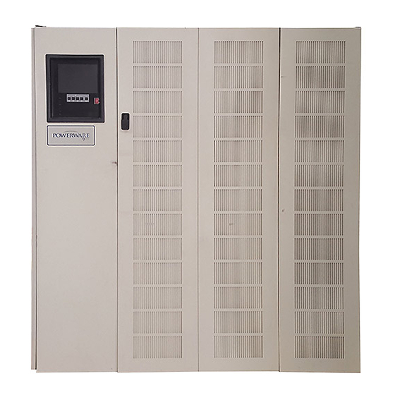
The UPS system is housed in a free-standing cabinet, divided into three sections to facilitate shipping. The cabinet sections line up and match in style and color, and have safety shields behind the doors for hazardous voltage protection. The following illustration depicts a typical Powerware 9315 (500 kVA---750 kVA) UPS System. MODULE BYPASS... -
Page 8: Using This Manual
The term UPS system refers to the entire power protection system — the UPS modules, battery strings and options or accessories installed. Powerware 9315 (500 kVA- -750 kVA) T1 and T3 Installation Addendum viii 164201244- - 001 REV. A 011500... -
Page 9: Safety Considerations
Battery maintenance or battery replacement should be performed only by authorized service personnel. · Observe all DANGER, CAUTION, and WARNING notices affixed to the inside and outside of the equipment. Powerware 9315 (500 kVA- -750 kVA) T1 and T3 Installation Addendum 164201244- - 001 REV. A 011500... -
Page 10: For More Information
For More Information This manual describes how to remove and install transformers T1 and T3. For information about the installation and operation of the Powerware 9315 (500 kVA ---750 kVA) UPS , refer to the following: 164201244 Powerware 9315 (500 kVA ---750 kVA) UPS Installation and... -
Page 11: Getting Started
500 VA then the voltage may be measured on either the primary or a tertiary winding. Test Jumpers Various Lengths (3 feet to 10 feet) Timing Device Watch, clock or stopwatch Powerware 9315 (500 kVA- -750 kVA) T1 and T3 Installation Addendum 1--1 164201244- - 001 REV. A 011500... -
Page 12: Removal And Installation Guidelines
Once Transformers T1 and T3 have been reinstalled, preliminary operational checks and startup must be performed. NOTE: Startup and operational checks should be performed only by authorized service personnel only. Powerware 9315 (500 kVA- -750 kVA) T1 and T3 Installation Addendum 1--2 164201244- - 001 REV. A 011500... -
Page 13: Removing Transformer T1
Disconnect blower connectors B8P1 through B11P1. Remove four front screws, and one left and one right side screw securing blower assembly B8---B11 (see figure 2---3). Powerware 9315 (500 kVA- -750 kVA) T1 and T3 Installation Addendum 2--1 164201244- - 001 REV. A 011500... -
Page 14: Disconnecting T1 Power Wiring
Disconnect and remove three jumper wires between terminal lugs H1and H21, H2 and H31, and H3 and H11. Disconnect transformer ground wire from cabinet base (see figure 2---2). Powerware 9315 (500 kVA- -750 kVA) T1 and T3 Installation Addendum 2--2 164201244- - 001 REV. A 011500... - Page 15 PANEL 1 PANEL 2 SCREWS (14 PLACES PER PANEL) PANEL 4 PANEL 3 Figure 2 ---1. Output/Inverter Cabinet Rear Panels Powerware 9315 (500 kVA- -750 kVA) T1 and T3 Installation Addendum 2--3 164201244- - 001 REV. A 011500...
- Page 16 CENTER CHANNEL SIDE TRANSFORMER BAFFLE SIDE REAR GROUND WIRE TRANSFORMER TRANSFORMER BAFFLE BAFFLE Figure 2 ---2. Output/Inverter Cabinet Rear Interior View Powerware 9315 (500 kVA- -750 kVA) T1 and T3 Installation Addendum 2--4 164201244- - 001 REV. A 011500...
- Page 17 BLOWER ASSEMBLY B12---B15 UPPER DEADFRONT PANEL TOP SCREWS LOWER BLOWER DEADFRONT ASSEMBLY PANEL B8---B11 Figure 2 ---3. Output/Inverter Cabinet Front Interior View Powerware 9315 (500 kVA- -750 kVA) T1 and T3 Installation Addendum 2--5 164201244- - 001 REV. A 011500...
- Page 18 FRONT BLOWER ASSEMBLY SIDE INVERTER B12---B15 INVERTER BAFFLE BAFFLE Figure 2 ---4. Output/Inverter Blower Assembly B12 ---B15 Inverter Baffles Powerware 9315 (500 kVA- -750 kVA) T1 and T3 Installation Addendum 2--6 164201244- - 001 REV. A 011500...
- Page 19 TRANSFORMER TERMINALS FRONT TRANSFORMER BAFFLE TRANSFORMER TERMINALS TRANSFORMER MOUNTING BOLTS (8 PLACES) Figure 2 ---5. Transformer T1 Wiring Powerware 9315 (500 kVA- -750 kVA) T1 and T3 Installation Addendum 2--7 164201244- - 001 REV. A 011500...
-
Page 20: Removing T1
Move transformer to shipping pallet and place on pallet. Secure transformer to shipping pallet and cover with packing material. Reinstall transformer mounting bolts into cabinet mounting holes for shipping. Powerware 9315 (500 kVA- -750 kVA) T1 and T3 Installation Addendum 2--8 164201244- - 001 REV. A 011500... -
Page 21: Assembly And Hardware Reinstallation
Install rear transformer baffle and secure with two screws(see figure 2---2). Install vertical center channel and secure with two top and two bottom screws (see figure 2---2). Powerware 9315 (500 kVA- -750 kVA) T1 and T3 Installation Addendum 2--9 164201244- - 001 REV. A 011500... - Page 22 Install doors and top door hinges. Close cabinet doors. Proceed to Chapter 3 Removing Transformer T3 of this manual. Powerware 9315 (500 kVA- -750 kVA) T1 and T3 Installation Addendum 2--10 164201244- - 001 REV. A 011500...
-
Page 23: Removing Transformer T3
Remove three screws securing vertical center channel bracket to cabinet, and remove bracket (see figure 3---3). Powerware 9315 (500 kVA- -750 kVA) T1 and T3 Installation Addendum 3--1 164201244- - 001 REV. A 011500... -
Page 24: Disconnecting T3 Power Wiring
Disconnect and remove two jumper wires between terminal lugs Y01 and Y02, and Y02 and Y03. Disconnect transformer ground wire from cabinet base (see figure 3---6). Powerware 9315 (500 kVA- -750 kVA) T1 and T3 Installation Addendum 3--2 164201244- - 001 REV. A 011500... - Page 25 PANEL 1 PANEL 2 SCREWS (14 PLACES PER PANEL) PANEL 4 PANEL 3 Figure 3 ---1. Input/Rectifier Cabinet Rear Panels Powerware 9315 (500 kVA- -750 kVA) T1 and T3 Installation Addendum 3--3 164201244- - 001 REV. A 011500...
- Page 26 CENTER CHANNEL REAR TRANSFORMER BAFFLE TRANSFORMER MOUNTING BOLTS (8 PLACES) Figure 3 ---2. Input/Rectifier Cabinet Rear Interior View Powerware 9315 (500 kVA- -750 kVA) T1 and T3 Installation Addendum 3--4 164201244- - 001 REV. A 011500...
- Page 27 CENTER CHANNEL BRACKET Figure 3 ---3. Center Channel Bracket Powerware 9315 (500 kVA- -750 kVA) T1 and T3 Installation Addendum 3--5 164201244- - 001 REV. A 011500...
- Page 28 BLOWER ASSEMBLY B1---B4 Figure 3 ---4. Input/Rectifier Cabinet Front Interior View with Blowers Powerware 9315 (500 kVA- -750 kVA) T1 and T3 Installation Addendum 3--6 164201244- - 001 REV. A 011500...
- Page 29 P4/J4 A2P1/A2J1 BOTTOM SCREWS CPT4 PANEL INPUT FILTER DEADFRONT PANEL A2 PANEL Figure 3 ---5. Input/Rectifier Cabinet Front Interior View Blowers Removed Powerware 9315 (500 kVA- -750 kVA) T1 and T3 Installation Addendum 3--7 164201244- - 001 REV. A 011500...
- Page 30 TRANSFORMER TERMINALS GROUND WIRE TRANSFORMER TERMINALS Figure 3 ---6. Transformer T3 Wiring Powerware 9315 (500 kVA- -750 kVA) T1 and T3 Installation Addendum 3--8 164201244- - 001 REV. A 011500...
-
Page 31: Removing T3
Move transformer to shipping pallet and place on pallet. Secure transformer to shipping pallet and cover with packing material. Reinstall transformer mounting bolts into cabinet mounting holes for shipping. Powerware 9315 (500 kVA- -750 kVA) T1 and T3 Installation Addendum 3--9 164201244- - 001 REV. A 011500... -
Page 32: Assembly And Hardware Reinstallation
(see figure 3---4). Secure blower assembly to base with five front screws. Secure three rear screws attaching blower assembly to base. Powerware 9315 (500 kVA- -750 kVA) T1 and T3 Installation Addendum 3--10 164201244- - 001 REV. A 011500... - Page 33 3. Secure with ten screws on top and sides and four screws at bottom of panel. Install doors and top door hinges. Close cabinet doors. Powerware 9315 (500 kVA- -750 kVA) T1 and T3 Installation Addendum 3--11 164201244- - 001 REV. A 011500...
- Page 34 This Page Intentionally Left Blank. Powerware 9315 (500 kVA- -750 kVA) T1 and T3 Installation Addendum 3--12 164201244- - 001 REV. A 011500...
-
Page 35: Installing Transformer T1
Insert the forklift between the pallet supports on the bottom of the unit. CAUTION: Do not tilt transformer more than 10 degrees from vertical. Powerware 9315 (500 kVA- -750 kVA) T1 and T3 Installation Addendum 4--1 164201244- - 001 REV. A 011500... -
Page 36: Transformer T1 Installation
Remove panel. Remove vertical center channel by removing two top and two bottom scews (see figure 4---3). Powerware 9315 (500 kVA- -750 kVA) T1 and T3 Installation Addendum 4--2 164201244- - 001 REV. A 011500... - Page 37 Remove eight screws from upper deadfront panel and remove panel. Remove eight screws from lower deadfront panel and remove panel. Remove front transformer baffle by removing two screws (see figure 4---6). Powerware 9315 (500 kVA- -750 kVA) T1 and T3 Installation Addendum 4--3 164201244- - 001 REV. A 011500...
- Page 38 PANEL 1 PANEL 2 SCREWS (14 PLACES PER PANEL) PANEL 4 PANEL 3 Figure 4 ---2. Output/Inverter Cabinet Rear Panels Powerware 9315 (500 kVA- -750 kVA) T1 and T3 Installation Addendum 4--4 164201244- - 001 REV. A 011500...
- Page 39 CENTER CHANNEL SIDE TRANSFORMER BAFFLE SIDE REAR GROUND WIRE TRANSFORMER TRANSFORMER- BAFFLE BAFFLE Figure 4 ---3. Output/Inverter Cabinet Rear Interior View Powerware 9315 (500 kVA- -750 kVA) T1 and T3 Installation Addendum 4--5 164201244- - 001 REV. A 011500...
- Page 40 BLOWER ASSEMBLY B12---B15 UPPER DEADFRONT PANEL TOP SCREWS LOWER BLOWER DEADFRONT ASSEMBLY PANEL B8---B11 Figure 4 ---4. Output/Inverter Cabinet Frontr Interior View Powerware 9315 (500 kVA- -750 kVA) T1 and T3 Installation Addendum 4--6 164201244- - 001 REV. A 011500...
- Page 41 FRONT BLOWER ASSEMBLY SIDE INVERTER B12---B15 INVERTER BAFFLE BAFFLE Figure 4 ---5. Output/Inverter Blower Assembly B12 ---B15 Inverter Baffles Powerware 9315 (500 kVA- -750 kVA) T1 and T3 Installation Addendum 4--7 164201244- - 001 REV. A 011500...
- Page 42 TRANSFORMER TERMINALS FRONT TRANSFORMER BAFFLE TRANSFORMER TERMINALS TRANSFORMER MOUNTING BOLTS (8 PLACES) Figure 4 ---6. Transformer T1 Wiring Powerware 9315 (500 kVA- -750 kVA) T1 and T3 Installation Addendum 4--8 164201244- - 001 REV. A 011500...
-
Page 43: Installing T1
Move transformer over mounting holes in cabinet base and lower transformer onto base. Secure transformer with eight mounting bolts, nuts, and washers (see figure 4---6). Powerware 9315 (500 kVA- -750 kVA) T1 and T3 Installation Addendum 4--9 164201244- - 001 REV. A 011500... -
Page 44: Reconnecting T1 Power Wiring
Tighten to the specified torque. See figure 4---6 for terminal lug locations and Drawing 164201244---001---1 for wiring diagram. Powerware 9315 (500 kVA- -750 kVA) T1 and T3 Installation Addendum 4--10 164201244- - 001 REV. A 011500... - Page 45 Used with 600 Volt units only 164A T1-X21 23(18.4) Used with 600 Volt units only 165A T1-X31 23(18.4) Used with 600 Volt units only Powerware 9315 (500 kVA- -750 kVA) T1 and T3 Installation Addendum 4--11 164201244- - 001 REV. A 011500...
- Page 46 DESCRIPTION: POWERWARE 9315 (500 kVA-- 750 kVA) T1 POWER WIRING DIAGRAM DRAWING NO: SHEET: 164201244---001---1 1 of 1 REVISION: DATE: 011500 Powerware 9315 (500 kVA- -750 kVA) T1 and T3 Installation Addendum 4--12 164201244- - 001 REV. A 011500...
-
Page 47: Assembly And Hardware Reinstallation
Install vertical center channel and secure with two top and two bottom scews (see figure 4---3). Proceed to Chapter 5 Installing Transformer T3 of this manual. Do not reinstall front doors or rear panels. Powerware 9315 (500 kVA- -750 kVA) T1 and T3 Installation Addendum 4--13 164201244- - 001 REV. A 011500... - Page 48 This Page Intentionally Left Blank. Powerware 9315 (500 kVA- -750 kVA) T1 and T3 Installation Addendum 4--14 164201244- - 001 REV. A 011500...
-
Page 49: Installing Transformer T3
Insert the forklift between the pallet supports on the bottom of the unit. CAUTION: Do not tilt transformer more than 10 degrees from vertical. Powerware 9315 (500 kVA- -750 kVA) T1 and T3 Installation Addendum 5--1 164201244- - 001 REV. A 011500... -
Page 50: Transformer T3 Installation
Remove panel. Remove panel 4 by loosening four screws at bottom of panel and removing six screws from sides. Remove panel. Powerware 9315 (500 kVA- -750 kVA) T1 and T3 Installation Addendum 5--2 164201244- - 001 REV. A 011500... - Page 51 Disconnect connector P4 from J4. Loosen three bottom screws on CPT4 panel. Remove three top screws from CPT4 panel and remove panel. Powerware 9315 (500 kVA- -750 kVA) T1 and T3 Installation Addendum 5--3 164201244- - 001 REV. A 011500...
- Page 52 PANEL 1 PANEL 2 SCREWS (14 PLACES PER PANEL) PANEL 4 PANEL 3 Figure 5 ---2. Input/Rectifier Cabinet Rear Panels Powerware 9315 (500 kVA- -750 kVA) T1 and T3 Installation Addendum 5--4 164201244- - 001 REV. A 011500...
- Page 53 CENTER CHANNEL REAR TRANSFORMER BAFFLE TRANSFORMER MOUNTING BOLTS (8 PLACES) Figure 5 ---3. Input/Rectifier Cabinet Rear Interior View Powerware 9315 (500 kVA- -750 kVA) T1 and T3 Installation Addendum 5--5 164201244- - 001 REV. A 011500...
- Page 54 CENTER CHANNEL BRACKET Figure 5 ---4. Center Channel Bracket Powerware 9315 (500 kVA- -750 kVA) T1 and T3 Installation Addendum 5--6 164201244- - 001 REV. A 011500...
- Page 55 BLOWER ASSEMBLY B1---B4 Figure 5 ---5. Input/Rectifier Cabinet Front Interior View with Blowers Powerware 9315 (500 kVA- -750 kVA) T1 and T3 Installation Addendum 5--7 164201244- - 001 REV. A 011500...
- Page 56 P4/J4 A2P1/A2J1 BOTTOM SCREWS CPT4 PANEL INPUT FILTER DEADFRONT PANEL A2 PANEL Figure 5 ---6. Input/Rectifier Cabinet Front Interior View Blowers Removed Powerware 9315 (500 kVA- -750 kVA) T1 and T3 Installation Addendum 5--8 164201244- - 001 REV. A 011500...
- Page 57 TRANSFORMER TERMINALS GROUND WIRE TRANSFORMER TERMINALS Figure 5 ---7. Transformer T3 Wiring Powerware 9315 (500 kVA- -750 kVA) T1 and T3 Installation Addendum 5--9 164201244- - 001 REV. A 011500...
-
Page 58: Installing T3
(one on back and one on front of bolt), one belleville washer, and one nut. Tighten to the specified torque. See figure 5---7 for terminal lug locations and Drawing 164201244---001---2 for wiring diagram. Powerware 9315 (500 kVA- -750 kVA) T1 and T3 Installation Addendum 5--10 164201244- - 001 REV. A 011500... - Page 59 Used when CB1 and Input Filter A2 are not required. Use longer bolt in top terminal lug hole. T3-Y1 23(18.4) T3-Y2 23(18.4) T3-Y3 23(18.4) T3-X1 23(18.4) T3-X2 23(18.4) T3-X3 23(18.4) Powerware 9315 (500 kVA- -750 kVA) T1 and T3 Installation Addendum 5--11 164201244- - 001 REV. A 011500...
- Page 60 DESCRIPTION: POWERWARE 9315 (500 kVA-- 750 kVA) T3 POWER WIRING DIAGRAM DRAWING NO: SHEET: 164201244---001---2 1 of 1 REVISION: DATE: 011500 Powerware 9315 (500 kVA- -750 kVA) T1 and T3 Installation Addendum 5--12 164201244- - 001 REV. A 011500...
-
Page 61: Assembly And Hardware Reinstallation
(see figure 5---5). Secure blower assembly to base with five front screws. Secure three rear screws attaching blower assembly to base. Powerware 9315 (500 kVA- -750 kVA) T1 and T3 Installation Addendum 5--13 164201244- - 001 REV. A 011500... - Page 62 Secure left side of transformer baffle to cabinet with one screw (see figure 5---3). Proceed to Chapter 6 Dielectric Testing in this manual. Do not reinstall front doors or rear panels. Powerware 9315 (500 kVA- -750 kVA) T1 and T3 Installation Addendum 5--14 164201244- - 001 REV. A 011500...
-
Page 63: Dielectric Testing
8 and 9 are coiled inside the Module Bypass Cabinet (MBC) and are attached at the factory to the input of the MBC. Powerware 9315 (500 kVA- -750 kVA) T1 and T3 Installation Addendum 6--1 164201244- - 001 REV. A 011500... - Page 64 Connect 3-pin control wiring harness connector P6 from the MBC to connector J6 on Inverter number 2 control board. Refer to Appendix A of the referenced installation manual for connector locations. Powerware 9315 (500 kVA- -750 kVA) T1 and T3 Installation Addendum 6--2 164201244- - 001 REV. A 011500...
-
Page 65: Single Module (Rt) Test Setup
Disconnect Power Supply 2 connector J1 (this isolates frame ground stand-off bond). Disconnect Power Supply 3 connector J1 (this isolates frame ground stand-off bond). Disconnect Bypass Control PCB connectors J1 and J2. Powerware 9315 (500 kVA- -750 kVA) T1 and T3 Installation Addendum 6--3 164201244- - 001 REV. A 011500... - Page 66 If installed, manually close CB1. If installed, manually close CB3. Install static switch in MBC cabinet. Manually close CBP . Manually close FBP . Powerware 9315 (500 kVA- -750 kVA) T1 and T3 Installation Addendum 6--4 164201244- - 001 REV. A 011500...
-
Page 67: Multi-Module Preparation
Disconnect Inverter Control (IGBT) PCB 2 connectors J9, J11, J12, J13, J14, J15, and J16. Disconnect Inverter Control (IGBT) PCB 3 connectors J9, J11, J12, J13, J14, J15, and J16. Powerware 9315 (500 kVA- -750 kVA) T1 and T3 Installation Addendum 6--5 164201244- - 001 REV. A 011500... - Page 68 B_Rect_E1 B_Rect_E2 B_Rect_E2 B_Rect_E3 Input_Filter_E2 Input_Filter_E2 Input_Filter_E4 Input_Filter_E4 Input_Filter_E6 A6_INVERTER_DC+ A6_INVERTER_ C A6_INVERTER_ C If installed, manually close CB1. If installed, manually close CB3. Powerware 9315 (500 kVA- -750 kVA) T1 and T3 Installation Addendum 6--6 164201244- - 001 REV. A 011500...
-
Page 69: Dielectric Testing
Energize the Dielectric equipment and apply the full test voltage for one minute. De---energize the Dielectric equipment and remove the red and black connections. Powerware 9315 (500 kVA- -750 kVA) T1 and T3 Installation Addendum 6--7 164201244- - 001 REV. A 011500... -
Page 70: Returning System To Normal
Connect SCR_Drive_B PCB connectors J1, J2, and J9. Connect Inverter Control (IGBT) PCB 1 connectors J9, J11, J12, J13, J14, J15, and J16. Powerware 9315 (500 kVA- -750 kVA) T1 and T3 Installation Addendum 6--8 164201244- - 001 REV. A 011500... - Page 71 Connect Power Supply 2 connector J1. Connect Machine Controller PCB connector J2. Open all circuit breakers. Proceed to Chapter 7 Final Assembly of this manual. Powerware 9315 (500 kVA- -750 kVA) T1 and T3 Installation Addendum 6--9 164201244- - 001 REV. A 011500...
- Page 72 This Page Intentionally Left Blank. Powerware 9315 (500 kVA- -750 kVA) T1 and T3 Installation Addendum 6--10 164201244- - 001 REV. A 011500...
-
Page 73: Final Assembly
Install doors and top door hinges. Proceed to installation of UPS contained in manual referenced in the Introduction of this manual. Powerware 9315 (500 kVA- -750 kVA) T1 and T3 Installation Addendum 7--1 164201244- - 001 REV. A 011500... - Page 74 This Page Intentionally Left Blank. Powerware 9315 (500 kVA- -750 kVA) T1 and T3 Installation Addendum 7--2 164201244- - 001 REV. A 011500...
Need help?
Do you have a question about the 9315 and is the answer not in the manual?
Questions and answers