Polycom 4000 Hardware Manual
Realpresence collaboration server
Hide thumbs
Also See for 4000:
- Administrator's manual (1130 pages) ,
- Installation and configuration manual (21 pages) ,
- Quick start manual (2 pages)

Related Manuals for Polycom 4000


Summary of Contents for Polycom 4000
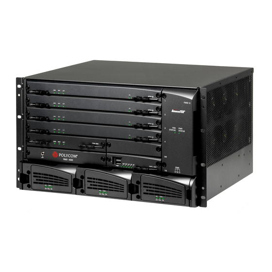
- Page 1 Hardware Guide DOC2749A Version 8.3 | January 2014 | RealPresence Collaboration Server (RMX) 4000...
-
Page 2: Patent Information
As between the parties, Polycom, Inc., retains title to and ownership of all proprietary rights with respect to the software contained within its products. The software is protected by United States copyright laws and international treaty provision. - Page 3 Installation of this equipment must comply with local and national electrical codes. Environmental This product is compliant with the requirements of the recast RoHS Directive 2011/65/EU. Information can be obtained from Polycom Ltd, 270 Bath Road, Slough, Berkshire, SL1 4DX, UK or via: RoHSinformation@polycom.com Information on recycling can be found at: www.polycom.com/WEEE...
- Page 4 2. This device must accept any interference received, including interference that may cause undesired operation. Modifications: Any modifications made to this device that are not approved by Polycom, Inc. may void the authority granted to the user by the FCC to operate this equipment.
- Page 5 Härmed intygar Polycom (UK) Ltd att denna Polycom RMX står I överensstämmelse med de väsentliga egenskapskrav och övriga relevanta bestämmelser som framgår av direktiv 1999/5/EG. A full copy of the Declaration of Conformity can be obtained from Polycom Ltd, 270 Bath Road, Slough, Berkshire, SL1 4DX, UK. Polycom, Inc.
- Page 6 When such trouble occurs, the user may be required to take corrective actions. Worldwide EMC statement This is a class A product. In a domestic environment this product may cause radio interference in which case the user may be required to take adequate measures. Polycom, Inc.
- Page 7 If trouble is experienced with this equipment, for repair or warranty information, please contact Polycom Inc in the U.S.A. 1-888-248-8294. If the equipment is causing harm to the telephone network, the telephone company may request that you disconnect the equipment until the problem is resolved.
-
Page 8: Table Of Contents
Rack Mount Safety Precautions ..........20 Installing the RealPresence Collaboration Server (RMX) 4000 ......21 Unpacking the RealPresence Collaboration Server (RMX) 4000 . - Page 9 Replacing the Fabric Switch Module (FSM 4000) ........
- Page 10 RealPresence®Collaboration Server 4000 Hardware Guide PRI Port Assignment ..........70...
-
Page 11: Realpresence Collaboration Server (Rmx) 4000 Hardware Description
RealPresence Collaboration Server (RMX) 4000 Hardware Description This Hardware Guide provides information on the RealPresence Collaboration Server (RMX) 4000 and its components. This system utilizes a modular “universal slot” platform, whose components are designed for high performance, capacity and reliance. - Page 12 RealPresence®Collaboration Server 4000 Hardware Guide ● RTM LAN Card(s): Routes data between the MPMx/MPMRx cards and components of the system, and sends media by IP packets and provides connectivity to external IP networks ● RTM IP Card: contains an Ethernet Switch that manages the network of the system ●...
-
Page 13: Realpresence Collaboration Server (Rmx) 4000 Specifications
15.74” (40 cm.) Weight Up to 40 Kg (88 lbs). Media Protocols Audio G.711a/u, G.722, G.722.1C, G.722.1, G.723.1, G.719 G.729A, Polycom Siren™ 14, Siren 22 (in mono or stereo) and Siren LPR. Video H.261, H.263, H.264, H.264 High Profile Network Interfaces IP, ISDN, PSTN and LAN H.323, SIP, ISDN, PSTN, VoIP, and LAN... -
Page 14: Realpresence Collaboration Server (Rmx) 4000 System Capacities
RealPresence®Collaboration Server 4000 Hardware Guide RealPresence Collaboration Server (RMX) 4000 System Capacities Conferencing Capacities The following table summarizes the different system capacities. System Functions and Capacities RMX 4000 System Functions MPMx Mode MPMRx Mode Maximum number of Video participants in a conference... -
Page 15: Mpmx Resource Capacities
RealPresence®Collaboration Server 4000 Hardware Guide System Functions and Capacities RMX 4000 System Functions MPMx Mode MPMRx Mode Maximum number of Gateway Profiles Maximum number of Reservations (internal Scheduler) 4000 4000 Resource Capacities MPMx Two MPMx card assemblies are available: MPMx-S (Single) and MPMx-D (Double) each offer different resource capacities, as summarized in the following three tables: System Resources are now reported in terms of HD720p30 CP ports. -
Page 16: Mpmrx Resource Capacities
RealPresence®Collaboration Server 4000 Hardware Guide MPMRx Resource Capacities The following sections list the resource capacities of the RMX 4000. MPMRx Resource Capacities in Non-Mixed CP and SVC Conferences The port consumption ratios of different calls against that of a HD720p30 call are as shown in this table. -
Page 17: Resource Capacities In Cp And Svc Mixed Conferences
RealPresence®Collaboration Server 4000 Hardware Guide MPMRx-S Non-Mixed Port Resource Capacities The following table lists the system capacities for each license in non-mixed conferences. Licensed Capacity for Systems with MPMRx-S card, Non-Mixed Conferences Licensed AVC SD AVC CIF Audio ports HD1080p60... -
Page 18: Total Resource Capacities In Video Switching (Vsw) Conferences
HD720p30 Total Resource Capacities in Video Switching (VSW) Conferences The table below lists the maximum resource capacities of RMX 4000 per line rate in VSW conferences (line rate being the deciding factor) when used with MPMRx cards. Resource Capacities in Video Switching (VSW) Conferences... -
Page 19: Total Resource Capacities Per Mpmrx-S Card In Cp & Svc Conferences
RealPresence®Collaboration Server 4000 Hardware Guide The table below lists the maximum resource capacities of the RMX 4000 per resolution in CP Conferencing and SVC modes when used with MPMRx-D card. Total Resource Capacities per MPMRx-D Card Resolutions Non-Mixed Endpoints Mixed Endpoints... -
Page 20: Safety Requirements
General Installation Precautions Attention: The RMX 4000 can weigh up to 40 kg when all slots are occupied. Two people are required to lift the MCU out of the box and also when installing it in a rack. ● Use a regulating uninterruptable power supply (UPS) to protect the RMX 4000 from power surges and voltage spikes, to keep your MCU operating in case of a power failure. -
Page 21: Installing The Realpresence Collaboration Server (Rmx) 4000
2 The RMX 4000 is shipped in a packing case with Stratocell® packaging, and the top cover must be unlocked and lifted where the RMX is placed on the inside of an anti-static plastic bag. - Page 22 Server (RMX) 4000 The ISDN card is shipped out of the box and must be manually installed into the rear of the RMX 4000. It is recommended that the ISDN card be installed before the RMX 4000 is installed in a rack. For more...
-
Page 23: Installing The Rmx In A Rack Or As A Standalone
Installing the RMX in a Rack or as a Standalone Either place the RMX 4000 on a hard, flat surface such as a desktop or mount it on a 19”/23” rack or a rack with telescopic rail runners. -
Page 24: Telescopic Rail Runner Assembly For Realpresence Collaboration Server
RealPresence®Collaboration Server 4000 Hardware Guide Telescopic Rail Runner Assembly for RealPresence Collaboration Server (RMX) 4000 Before installing the telescopic rail runners in the rack, make sure that the kit has the following parts. Rail Runners Kit Contents Item Item Part/Kit no. -
Page 25: Telescopic Rail Runner Assembly
RealPresence®Collaboration Server 4000 Hardware Guide Rail Runners Kit Contents Item Item Part/Kit no. Item Item Sample Quantity Rail runner assembly kit Flat head screw - M3*8mm Flat washer M3 Nut spring M3 RMX chassis assembly Pan head screw - M5*12mm... - Page 26 RealPresence®Collaboration Server 4000 Hardware Guide Front view of RMX Rail Runner Assembly 2 Position the Rack Spacer (3) onto the marked rack post together with left rack rail runner (1) and fasten the flat head screws 3*10mm (4) as shown in the following figure.
- Page 27 3 Adjust the telescopic rack rail runner to the rack opening and mount it onto the marked position of the rear post as described in step 2. Detail of Rear RMX 4000 Rack Spacer Assembly 4 Repeat steps 2 and 3 for the right rack rail runner.
-
Page 28: Optional 19" Rack Assembly
RealPresence®Collaboration Server 4000 Hardware Guide Attention: Two people are required to lift the MCU out of the box and when installing it in a rack. RMX 4000 Bolt Installation Optional 19” Rack Assembly 1 When the RMX is to be rack-mounted, chassis runners must be installed on the rack as shown in the figure below. - Page 29 RealPresence®Collaboration Server 4000 Hardware Guide Installing Chassis Runners and the RMX 4000 in a Rack 2 Mount the RMX on top of the rack brackets using the blades or placing it on a rack mount shelf with runners. 3 Fasten the RMX to the rack with 8 screws into the holes provided on the RMX’s front as shown below.
- Page 30 Rack mounting screws must be supplied by the rack’s manufacturer. The airflow of the RMX 4000 is from right to left. Be sure that the areas on the left and right side of the system are clear for proper ventilation.
-
Page 31: Mounting The Realpresence Collaboration Server (Rmx) 4000 In A 23" Rack
Rack mounting screws must be supplied by the rack’s manufacturer. The airflow of the RMX 4000 is from right to left. Be sure that the areas on the left and right side of the system are clear for proper ventilation. -
Page 32: Reverse Mounting The Realpresence Collaboration Server (Rmx) 4000 In A Rack
(tinned or untinned). Wire, bus bar or braided strap connectors are acceptable. Reverse Mounting the RealPresence Collaboration Server (RMX) 4000 in a Rack It is possible to reverse mount the RMX 4000 in a rack using 19” or 23” brackets. To reverse mount the RMX 4000 on a 19” rack: 1 Remove the handles and brackets from the front of the RMX. -
Page 33: Connecting The Realpresence Collaboration Server (Rmx) 4000 To Power Sources
Do not connect the green or green-yellow wire to the system single-point ground screw. • Customers are required to only use AC power cables supplied by Polycom. • The size of the protective earthing conductor should be a minimum of 10 AWG. -
Page 34: Selv Power
1 Make sure that the power button is switched OFF on the RMX 4000. 2 Insert the power cables into the power connectors on the rear panel of the RMX 4000. Connecting the RealPresence Collaboration Server (RMX) 4000 to -48DC SELV... - Page 35 -48 VDC terminal block and the red wire to the RTN terminal block. • A 10 AWG cable must be used to connect the mains with the RMX 4000 DC Power Rail Module. • The supply wires for DC version must be terminated using quick connectors.
-
Page 36: (Rmx) 4000
● RTM LAN type cards: When an RTM LAN - 4 port card is installed on the RMX 4000, connect the LAN cable to LAN 2*. • An MPMx/MPMRx card on the front of the RMX must always be seated or connected opposite to either an RTM LAN - 4 ports or RTM ISDN card on the rear of the chassis. - Page 37 RealPresence®Collaboration Server 4000 Hardware Guide When an RTM LAN - 2 port card is installed on the RMX 4000, connect the LAN cable to LAN 2. • An MPMx/MPMRx card on the front of the RMX must always be seated or connected opposite to either an RTM LAN - 2 ports or RTM ISDN card on the rear of the chassis.
-
Page 38: First-Time Power-Up
ON. 3 Remove the USB key. RealPresence Collaboration Server (RMX) 4000 Components On the RMX 4000 components are located on both the front and rear of the MCU as listed in RMX 4000 Component Description. For more information see the descriptions of the... - Page 39 RealPresence®Collaboration Server 4000 Hardware Guide RMX 4000 AC Front View Polycom, Inc.
- Page 40 RealPresence®Collaboration Server 4000 Hardware Guide RMX 4000 DC Front View Polycom, Inc.
-
Page 41: Mpmx And Mpmrx Media Cards
Multi Processor Module x The MPMx cards, perform the various RTP, audio and video processing functions on (MPMx) Card the RMX 4000 unit. TI processors are at the core of each MPMx card which are available in the following assemblies: •... -
Page 42: Realpresence Collaboration Server (Rmx) 4000 Rear Panel
MUST be present in a rear panel slot opposite to an MPMx/MPMRx card. A single RTM-IP 4000 card must also be located on slot 17 in the rear of the RMX 4000. In addition, the rear panel houses the main AC power switch, AC Power Entry Modules (PEMs) or DC Power Rail Modules (PRMs), and additional communications ports. -
Page 43: Rtm-Ip 4000
On some DC modules LED indications may not be present. RTM-IP 4000 A single RTM-IP 4000 card provides system management based on the ATCA standard and connects to the backplane. Through the shelf manager, it controls and monitors the system fans and regulates the AC power supplies. - Page 44 Do not remove the protective plastic caps from LAN 1, LAN 4 and LAN 5 ports. RMX4000 RTM-IP Rear Panel The following items appear on the RMX 4000 rear panel: RMX 4000 Rear Panel - RTM-IP 4000 Component Description Item...
-
Page 45: Rtm Isdn
– the RTM ISDN card can be installed in any two rear panel card slots. Up to two RTM ISDN cards can be installed in one RMX 4000. Up to a total of 14 E1 or 18 T1 PRI cables can be installed with two RTM ISDN cards. -
Page 46: Rtm Lan Card - With 4 Lan Ports
RTM LAN card must be installed in the rear panel slot at the same level as the MPMx/MPMRx card. On the RMX 4000, LAN port 2 is used to connect the LAN cable. Port 1 is the redundant port*. -
Page 47: Dc Power Rail Module
RMX must be switched OFF from the two circuit switches and the mains. Component Slot Allocation On the RMX 4000, components have been assigned dedicated slots as defined in the following table. Slot numbers are located on both the front and rear of the RMX 4000. - Page 48 With DC power, two power supplies are installed with the 2nd redundant. The center slot (#20) on the rear of the RMX 4000 is disabled and is fitted with blank panel. Note: Protective bonding conductor size is 14AWG (1.5mm) within the Power Entry Model.
-
Page 49: Realpresence Collaboration Server (Rmx) 4000 Leds
The LEDs on the rear panel indicate the state of the external connections and the status of the RTM-IP 4000 card. RealPresence Collaboration Server (RMX) 4000 Front Panel LEDs The following items appear on the RMX 4000 front panel. RMX 4000 Front Panel LEDs Component... - Page 50 Blue Flashes - Shut down process initiated by lightly pulling the CPU ejector levers. This LED flashes in synchronization with the CNTL 4000’s card’s HS LED. ON - Card is in a power down mode. Card removal Initiated - The card can be removed safely once the CPU ejector levers are fully open.
-
Page 51: Realpresence Collaboration Server (Rmx) 4000 Rear Panel Leds
MPMx/MPMRx’s cards HS LED. OFF - Normal ON - CPU may be removed. RealPresence Collaboration Server (RMX) 4000 Rear Panel LEDs RTM-IP 4000 The following LEDs appear on the RTM-IP 4000 card. RTM-IP 4000 LEDs Component LED Name LED Color Description... -
Page 52: Rtm Lan Leds - With 4 Lan Ports
Flashes - During system startup. Amber ON - Packet flow to and from the MCU chassis. Flashes - During system startup. Green ON - RTM-IP 4000 card has successfully completed startup. Flashes - During system startup. Blue Hot Swap not supported. OFF - Normal. -
Page 53: Rtm Isdn
RealPresence®Collaboration Server 4000 Hardware Guide The following LEDs appear on the RTM LAN - 2 ports: Function Name LED Name LED Color Description LAN 1-2 LEDs 1 Gb Green ON with an active network connection, flickers with Packet activity. Amber ON when 1Gb connection is online, flickers with Packet activity. -
Page 54: Dc Power Rail Leds
RealPresence®Collaboration Server 4000 Hardware Guide DC Power Rail LEDs The following LEDs appear on the DC Power Rail. RMX 4000 DC Power Rail LEDs Function Name LED Name LED Color Description DC Power POWER OK Green ON - Power input is within required voltage specifications: -38.5V to -70V... -
Page 55: Realpresence Collaboration Server (Rmx) 4000 Component Replacement
RealPresence Collaboration Server (RMX) 4000 Component Replacement The RMX 4000 is designed with ease of maintenance in mind. Most components are swappable and are accessible directly via the front panel or the rear panel. The MPMx/MPMRx power supplies and Fan tray are Hot Swappable. The Fan tray must be replaced immediately or the temperature spike in the RMX will initiate a shutdown. -
Page 56: Using The Modified Pmc Compatible Ejector Lever
RealPresence®Collaboration Server 4000 Hardware Guide Using the Modified PMC Compatible Ejector Lever On the RMX 4000 most components are fitted with identical ejector levers that are used to release or fasten the components to their slot. The ejector levers can be moved to three positions: 1 Closed/Locked - The ejector levers are pushed up against the card’s panel and the lock catch is in... -
Page 57: Replacing An Ac Power Supply Module
10 Turn ON the RMX 4000. Replacing an AC Power Supply Module Two units supply power to the RMX 4000 (3rd optional - AC only), each unit with its own power cord. Use the following procedure to replace a Power Supply unit. -
Page 58: Replacing An Ac Power Entry Module (Pem)
On the rear of the RMX three AC PEM’s are fitted, each with their own power cord. Use the following procedure to replace a Power Entry Module (PEM). Please verify the type of PEM used on your RMX 4000. Do not insert a PEM of a different type on your system. -
Page 59: Replacing A Dc Power Rail Module (Prm)
1 Turn OFF the circuit switch on the each of the DC PRMs and from the Mains. 2 Verify that DC PRM unit you are about to replace on the RMX 4000 is not HOT or has any Live current feeds. -
Page 60: Replacing The Fan Drawer
RealPresence®Collaboration Server 4000 Hardware Guide 4 Using a star screw driver, disconnect the two wires connected to the Terminal block (-48 VDC & RTN) of the failed DC PRM unit. 5 Unscrew the captive screws on the rear panel of the PRM unit that secures the unit to the chassis. -
Page 61: Inserting An Air Filter (Optional) In The Fan Drawer
To insert an air filter in the fan drawer: 1 Ensure that the power switch/circuit switch on the RMX 4000 is turned OFF (O). Warning! The air filter cannot be replaced when the RMX 4000 unit is ON. - Page 62 10 Push the Fan drawer firmly into the Backplane, making sure it is properly seated in its slot. 11 Tighten the captive screws on the front panel of the Fan drawer to the chassis. 12 Turn ON the RMX 4000. It is recommended that the air filter be replaced or cleaned every six months.
-
Page 63: Removing A Faulty Mpmx/Mpmrx Card
When upgrading from MPM+ to MPMrx, all connections to the RTM-IP 4000 require Ferrite cables. All MPMx/MPMRx cards can be installed or removed while the RMX 4000 is powered on and operating. Prior to removing an MPMx/MPMRx card the captive screws must be unscrewed and the ejector levers must be opened to initiate a “power down”... -
Page 64: (Rmx) 4000
Installing or Replacing MPMx/MPMRx Card on the RealPresence Collaboration Server (RMX) 4000 All MPMx/MPMRx cards can be installed or removed while the RMX 4000 is powered on and operating. When upgrading from MPM/MPM+ to MPMRx, all connections to the RTM-IP 4000 require Ferrite cables. -
Page 65: Installing Or Replacing The Rtm Isdn Card
To remove an RTM LAN or existing ISDN card: 1 Ensure that the power switch on the RMX 4000 is turned OFF (O). 2 Remove the RTM LAN or RTM ISDN card by unscrewing the captive screws that fasten the card to the RMX. - Page 66 RealPresence®Collaboration Server 4000 Hardware Guide 3 Push the card into the slot until the ejector levers touch the front edge of the card cage. Push the ejector levers to their fully closed position. 4 Tighten the captive screws on each side of the rear panel of the card, securing the RTM ISDN card to the MCU.
-
Page 67: Replacing The Rtm-Ip 4000 Card
Replacing the RTM-IP 4000 Card RTM-IP 4000 connections require Ferrite cables when connecting to MPMx/MPRx cards. The RTM-IP 4000 card on the rear of the RMX 4000 provides connectivity to all the MCU modules. Use the following procedure to replace the RTM-IP 4000 card. -
Page 68: Replacing The Rtm Lan
12 Turn ON the RMX 4000. Replacing the RTM LAN The RTM LAN card on the rear of the RMX 4000 provides connectivity to all the MCU modules. Use the following procedure to replace the RTM LAN card. To replace the RTM- LAN card: 1 Ensure that the power switch/circuit switch on the RMX 4000 is turned OFF (O). -
Page 69: Replacing The Fabric Switch Module (Fsm 4000)
8 Ensure that the metal ejector levers are fully retracted into their housings. 9 Tighten the captive screws on the rear panel of the RMX 4000 that secure the Fabric Switch Module (FSM 4000). 10 Turn ON the RMX 4000. -
Page 70: Pri Port Assignment
PRI Port Assignment Signal Name Receive Ring Receive Tip No connection Transmit Ring Transmit Tip No connection No connection No connection Polycom, Inc.
Need help?
Do you have a question about the 4000 and is the answer not in the manual?
Questions and answers