Polycom RealPresence RMX 4000 Hardware Manual
Collaboration server
Hide thumbs
Also See for RealPresence RMX 4000:
- Hardware manual (68 pages) ,
- Installation & quick start manual (2 pages) ,
- Administrator's manual (1186 pages)
Table of Contents
Advertisement
Quick Links
Download this manual
See also:
Administrator's Manual
Advertisement
Table of Contents

Related Manuals for Polycom RealPresence RMX 4000


Summary of Contents for Polycom RealPresence RMX 4000
- Page 1 Hardware Guide Version 8.5 | December 2014 | 3725-74540-000/A ® RealPresence Collaboration ® Server (RMX ) 4000...
- Page 2 Polycom up to three (3) years after the distribution date of the applicable product or software at a charge not greater than the cost to Polycom of shipping or distributing the software to you. To receive software information, as well as the open source software code used in this product, contact Polycom by email at OpenSourceVideo@polycom.com.
- Page 3 Installation of this equipment must comply with local and national electrical codes. Environmental This product is compliant with the requirements of the recast RoHS Directive 2011/65/EU. Information can be obtained from Polycom Ltd, 270 Bath Road, Slough, Berkshire, SL1 4DX, UK or via: RoHSinformation@polycom.com Information on recycling can be found at: www.polycom.com/WEEE...
- Page 4 2. This device must accept any interference received, including interference that may cause undesired operation. Modifications: Any modifications made to this device that are not approved by Polycom, Inc. may void the authority granted to the user by the FCC to operate this equipment.
- Page 5 Härmed intygar Polycom (UK) Ltd att denna Polycom RMX står I överensstämmelse med de väsentliga egenskapskrav och övriga relevanta bestämmelser som framgår av direktiv 1999/5/EG. A full copy of the Declaration of Conformity can be obtained from Polycom Ltd, 270 Bath Road, Slough, Berkshire, SL1 4DX, UK. Polycom, Inc.
- Page 6 When such trouble occurs, the user may be required to take corrective actions. Worldwide EMC statement This is a class A product. In a domestic environment this product may cause radio interference in which case the user may be required to take adequate measures. Polycom, Inc.
- Page 7 If trouble is experienced with this equipment, for repair or warranty information, please contact Polycom Inc in the U.S.A. 1-888-248-8294. If the equipment is causing harm to the telephone network, the telephone company may request that you disconnect the equipment until the problem is resolved.
-
Page 8: Table Of Contents
Connect the RealPresence Collaboration Server (RMX) 4000 to Power Sources ..36 Connect Cables to the RealPresence Collaboration Server (RMX) 4000 ....39 Polycom, Inc. - Page 9 DBG (Debug) Port Pin Assignment ......... . 85 Polycom, Inc.
-
Page 10: Realpresence ® Collaboration Server (Rmx ® ) 4000 Hardware Specifications
● Easy integration of conference elements into external network management ● Enhanced Continuous Presence (multi-image video) ● IVR (Interactive Voice Response) module ● Resilient multipoint conferencing - Polycom Lost Packet Recovery (LPR) Main Components The Main components on the system are: ●... - Page 11 IP packets and provides connectivity to external IP networks ● RTM IP Card: contains an Ethernet Switch that manages the network of the system ● RTM ISDN card(s): Converts ISDN T1/E1 media to IP packets and provides connectivity to external ISDN networks Polycom, Inc.
-
Page 12: Realpresence Collaboration Server (Rmx) 4000 Specifications
15.74” (40 cm.) Weight Up to 40 Kg (88 lbs). Media Protocols Audio G.711a/u, G.722, G.722.1C, G.722.1, G.723.1, G.719 G.729A, Polycom Siren™ 14, Siren 22 (in mono or stereo) and Siren LPR. Video H.261, H.263, H.264, H.264 High Profile Network Interfaces IP, ISDN and LAN H.323, SIP, H.320, ISDN-Voice, VoIP, and LAN... -
Page 13: Realpresence Collaboration Server (Rmx) 4000 System Capacities
Maximum number of ISDN Services Maximum number of IVR Services Maximum number of Recording Links 20 (default) 20 (default) Maximum number of IVR Video Slides Maximum number of CDR Files 4000 4000 Maximum number of Fault Files 1000 1000 Polycom, Inc. -
Page 14: Mpmx Resource Capacities
The following table lists maximum resource capacities of MPMx card in non-mixed conferences. Maximum Resource Capacities Licenses Port Ratios MPMx-S Capacities MPMx-D Capacities 720p RTV 1.00 720p TIP 1.00 SVC 1080 SVC 720 3.00 Audio 180* 360* 3.00 SD (4CIF) 2.00 720p30 1.00 1080p30 1080p60 Asymmetric 0.33 1080p60 In voice‐only mode–all DSPs are set as ART. Polycom, Inc. -
Page 15: Mpmx Resource Capacities In Mixed Conferences
180* SD (4CIF) 720p30 1080p30 1080p60 Asymmetric NA** NA** 1080p60 In voice‐only mode–all DSPs are set as ART. Requires mix mode conference in motion mode. MPMx Resource Capacity per Line Rate in VSW Resource Type MPMx VSW 2Mbps VSW 4Mbps VSW 6Mbps ISDN 7 E1 or 9 T1 per ISDN card Polycom, Inc. -
Page 16: Mpmrx Resource Capacities
The following table lists port resource capacities of MPMRx-D card per conference license type per conference type in non-mixed conferences. MPMRx-D Port Resource Capacities per License Type per Conference Type Licenses 1080p60 1080p30 HD720p30 AVC SD AVC CIF Audio SVC 720p SVC 1080p Polycom, Inc. - Page 17 1.00 2.00 2.00 3.75 3.00 1.88 0.25 0.49 1.00 2.00 2.00 3.53 3.00 1.76 0.24 0.50 1.00 2.00 2.00 3.33 3.00 1.67 0.24 0.49 1.00 2.00 2.00 3.16 3.00 1.58 0.25 0.50 1.00 2.00 2.00 3.00 3.00 1.50 Polycom, Inc.
-
Page 18: Mpmrx-D Resource Capacities In Mixed Cp And Svc Conferences
MPMRx-D Port Resource Capacities per License Type per Conference Type Licenses 1080p60 1080p30 HD720p30 AVC SD AVC CIF Audio SVC 720p SVC 1080p The following table lists license ratios of MPMRx-D card per conference license type per conference type in CP and SVC mixed conferences. Polycom, Inc. - Page 19 0.66 1.25 1.25 1.88 2.50 1.88 0.21 0.40 0.66 1.18 1.18 1.76 2.35 1.76 0.22 0.40 0.67 1.11 1.11 1.67 2.22 1.67 0.22 0.40 0.66 1.05 1.05 1.58 2.11 1.58 0.22 0.40 0.66 1.00 1.00 1.50 2.00 1.50 Polycom, Inc.
-
Page 20: Mpmrx-S Resource Capacities In Non-Mixed Conferences
1.00 2.00 2.00 12.00 3.00 3.00 0.20 0.47 1.00 2.00 2.00 12.00 3.00 3.00 0.25 0.50 1.00 2.00 2.00 12.00 3.00 3.00 0.24 0.48 1.00 2.00 2.00 12.00 3.00 3.00 0.23 0.50 1.00 2.00 2.00 10.00 3.00 3.00 Polycom, Inc. -
Page 21: Mpmrx-S Resource Capacities In Mixed Cp And Svc Conferences
0.60 1.30 1.30 12.00 3.00 3.00 0.20 0.40 0.67 1.33 1.33 10.00 3.00 3.00 0.20 0.40 0.65 1.30 1.30 7.50 3.00 3.00 0.20 0.40 0.64 1.32 1.32 6.00 3.00 3.00 0.20 0.40 0.67 1.33 1.33 5.00 2.50 2.50 Polycom, Inc. -
Page 22: Prepare The Hardware Installation Site
Server (RMX) 4000 unit. It should be situated in a clean, dust-free area that is well ventilated. Avoid areas where heat, electrical noise and electromagnetic fields are generated. You will also need to place it near a grounded power outlet. Polycom, Inc. -
Page 23: General Installation Precautions
● Before you install the rails, determine the placement of each component in the rack. ● Install the heaviest components on the bottom of the rack first, and then work up. ● Always keep the rack trays and card slots closed when not servicing, to maintain proper cooling. Polycom, Inc. -
Page 24: Unpack The Realpresence Collaboration Server (Rmx) 4000
Installation Accessories. Rack Installation Accessories. Optional - ISDN Package. 3 Write down the Collaboration Server’s serial number from the sticker on the back of the unit. You will need it for product registration later in the process. Polycom, Inc. - Page 25 Remove any packaging material prior to positioning the RealPresence Collaboration Server (RMX) 4000. Caution: Two people are required Two people are required to lift the MCU out of the box and when installing it in a rack. Polycom, Inc.
-
Page 26: Verify The Accessories Kits
Right rail runner (two types See Figure 1-1 available: item (a) with or (b) without rail runner clip Note: The rail runner clip is designed to attach and clip onto the chassis runner frame. Polycom, Inc. - Page 27 Rack spacer assembly kit Rack spacer Front & Rear Flat head screw - M5*10mm Rail runner assembly kit Flat head screw - M3*8mm Flat washer M3 Nut spring M3 RMX chassis assembly Pan head screw - M5*12mm Flat washer M5 Polycom, Inc.
-
Page 28: Install The Telescopic Rail Runner On The Rack
Use the rack spacer (3) to predetermine its position on the rack post, making sure that the square studs of the spacer fit into the rack post square/rounded mounting holes. Mark the spacer location on the rack post. Repeat this process for the 3 remaining vertical posts ensuring that the system can be horizontally seated. Polycom, Inc. - Page 29 2 Position the rack spacer (3) onto the marked rack post together with left rack rail runner (1) and fasten the flat head screws 3*10mm (4) as shown in the following figure. Detail of front rack spacer assembly (left rail runner is shown here) Polycom, Inc.
- Page 30 Detail of left rail runner (front internal view) Note: Number of screws needed The number of screws you will install depends on the rack width. 6 Repeat Step 5 for the right rack rail runner. Polycom, Inc.
-
Page 31: Install The Realpresence Collaboration Server (Rmx) 4000
2 Remove the RTM LAN or blank cover by unscrewing the captive screws that fasten the card or the cover to the Collaboration Server. When removing a card, use the metal ejector levers to pull the RTM LAN card out of its slot from the backplane. Polycom, Inc. -
Page 32: Install The Realpresence Collaboration Server (Rmx) 4000 As A Standalone System
Perform the following steps to mount the RealPresence Collaboration Server (RMX) 4000 in a Rack. Rack Mount Preparations ● Optional. Depending on the rack installed in your site, you may need to remove the handles if they are attached to the RealPresence Collaboration Server (RMX) 4000. Polycom, Inc. - Page 33 ● Using rack rail runners on the rack Install the telescopic rail runners, as described in Install the Telescopic Rail Runner on the Rack Mount the RealPresence Collaboration Server (RMX) 4000 on top of the rail runners. Polycom, Inc.
- Page 34 When the unit is installed on a rack, the rack must be properly grounded to the central office ground. The rack must be grounded with two-hole compression-type connectors using copper conductors (tinned or untinned). Wire, bus bar or braided strap connectors are acceptable. Polycom, Inc.
- Page 35 4 Fasten the RealPresence Collaboration Server (RMX) 4000 to the rack with eight screws into the holes provided on the RealPresence Collaboration Server (RMX) 4000 front as shown in figure above. Rack mounting screws must be supplied by the rack manufacturer. Polycom, Inc.
-
Page 36: Connect The Realpresence Collaboration Server (Rmx) 4000 To Power Sources
● Listed fastening hardware must be compatible with the materials being joined and must be preclude loosening, deterioration and electrochemical corrosion of the hardware and joint materials. To connect the Collaboration Server 4000 to AC power 1 Make sure that the power button is switched OFF on the RealPresence Collaboration Server (RMX) 4000. Polycom, Inc. - Page 37 Do not connect the green or green-yellow wire to the system single-point ground screw. • Customers are required to only use AC power cables supplied by Polycom. • The size of the protective earthing conductor should be a minimum of 10 AWG.
- Page 38 7 Turn ON the circuit breaker on each of the DC PEMs. On the RealPresence Collaboration Server (RMX) 4000, two types of circuit breakers can be installed: ● ON/OFF circuit breaker-Type A ● ON/OFF circuit breaker with locking mechanism-Type B Polycom, Inc.
-
Page 39: Connect Cables To The Realpresence Collaboration Server (Rmx) 4000
Collaboration Server (RMX) 1500/1800/2000/4000 Administrator’s Guide. ● Optional. RTM ISDN Card: If either RTM ISDN card is selected to install with MPMx or MPMRx card. Perform following steps to finish the cable connections on the RTM ISDN card: Polycom, Inc. - Page 40 In MPMRx card mode, connect the LAN cable to LAN1 and LAN 2. In MPMx card mode, connect the LAN cable to LAN 3 and LAN 4. RealPresence Collaboration Server (RMX) 4000 rear panel with AC powers and communication cables Polycom, Inc.
-
Page 41: Realpresence Collaboration Server (Rmx) 4000 Components And Components Replacement
The front panel provides access to the RMX 4000 main CNTL 4000 module, Fabric Switch Module (FSM 4000), MPMx/MPMRx modules, Power Supply drawers, Status LEDs, and Fan drawer. The figure below shows the front panel of the RMX 4000 fitted with AC Power supplies. RMX 4000 AC front view Polycom, Inc. - Page 42 RealPresence Collaboration Server (RMX) 4000 Components and Components Replacement RMX 4000 DC front view Polycom, Inc.
- Page 43 RTM LAN Card - four LAN Ports The RMX unit can work with either MPMx or MPMRx (but not with both simultaneously) media cards. The card type installed in the system determines the Card Configuration Mode. ISDN support is the same for all Polycom, Inc.
- Page 44 Installing or swapping MPMx and MPMRx cards while the system is off will not cause a switch in the Card Configuration Mode when the system is restarted – it will restart in the Card Configuration Mode that was active previous to powering down. Polycom, Inc.
-
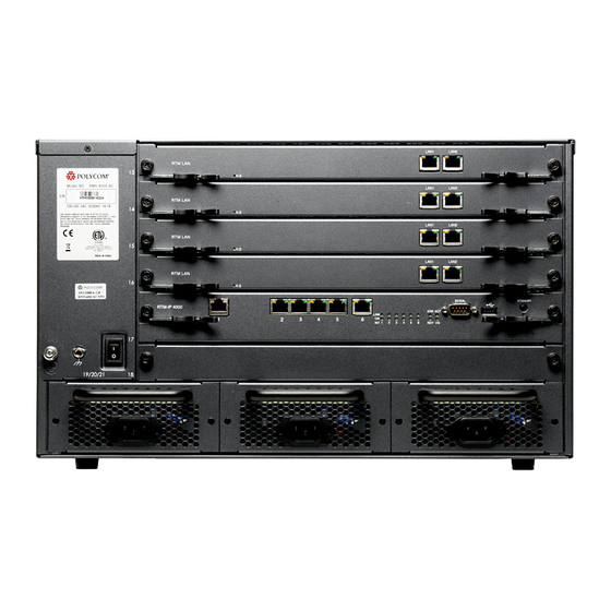
Page 45: Realpresence Collaboration Server (Rmx) 4000 Rear Panel
A single RTM IP 4000 card must also be located on slot 17 in the rear of the RMX 4000. In addition, the rear panel houses the main AC power switch, AC or DC PEMs, and additional communications ports. RMX 4000 AC Rear View Polycom, Inc. - Page 46 RealPresence Collaboration Server (RMX) 4000 Components and Components Replacement RMX 4000 DC Rear View Note: DC modules LED indications On some DC modules LED indications may not be present. Polycom, Inc.
- Page 47 LAN 4, LAN 5 and the Serial ports are only for debugging and not for customer use. • Do not remove the protective plastic caps from LAN 1, LAN 4 and LAN 5 ports. For pin assignment information, see Pin Assignment of Ports on the RTM IP 4000 Card RMX4000 RTM IP rear panel Polycom, Inc.
- Page 48 Toggle between ON/OFF and standby. Use this button to either perform Diagnostics or Software Recovery on the RMX after turning the system ON. Short press (2 seconds) - MPMx Diagnostics. Long press - (10 seconds) Media and RTM IP 4000 Software Recovery. Polycom, Inc.
- Page 49 E1 and T1 spans cannot be connected simultaneously to the same card, therefore, it is not possible to have a mixed E1 and T1 ISDN Network Service ● One 1Gb LAN port: Note: 200 audio participants The RTM ISDN card supports 200 audio participants, regardless of whether the spans are E1 or T1. Polycom, Inc.
- Page 50 ARM/CM is a switch for technician or field support use. The switch decides the output source between CM or DSP UART for DBG port. For pin assignment information, see Pin Assignment of Ports on the RTM ISDN Card Polycom, Inc.
- Page 51 This clock is used to synchronize ISDN spans only (it is not the system clock). A single clock source triggers an alarm that can be turned off by setting the appropriate flag in the system configuration. Polycom, Inc.
- Page 52 RTM LAN Card - four LAN Ports Ports on the four ports RTM LAN card are: ● Four 1Gb LAN ports No. 1-4 ● One DBG port - Debug port, for internal use. ● ARM/CM - Switch, for internal use. Polycom, Inc.
- Page 53 Each DC PEM has its own dedicated power cable. The circuit switch on the rear of the RMX activates independently any PEM installed on the RMX. A DC system has two DC PEMs, one for each power rail. Polycom, Inc.
-
Page 54: Component Slot Allocation
With DC power, two power supplies are installed with the 2nd redundant. The center slot (#20) on the rear of the RMX 4000 is disabled and is fitted with blank panel. Note: Protective bonding conductor size is 14AWG (1.5mm) within the Power Entry Model. Polycom, Inc. -
Page 55: Realpresence Collaboration Server (Rmx) 4000 Leds
LEDs are OFF. LED’s Fabric Switch Module ON - Major error on card. (FSM 4000) Flashes - During card startup. Green ON - The card has completed startup successfully. Flashes - During card startup. Orange Not in use. Polycom, Inc. - Page 56 OFF - Turns OFF when the ERR red LED is activated. Flashes - During system startup. Maroon ON - At least one endpoint is connected to the system. Flashes - During system startup. OFF - Normal. Flashes - Hard disk is active. Polycom, Inc.
- Page 57 CNTL 4000 Unit (continued) Blue/Red Flashes - Indicates when the power down process is initiated on an MPMx/MPMRx card. This LED flashes in synchronization with the MPMx/MPMRx cards HS LED. OFF - Normal ON - CPU may be removed. Polycom, Inc.
-
Page 58: Realpresence Collaboration Server (Rmx) 4000 Rear Panel Leds
ON - Packet flow to and from the MCU chassis. Flashes - During system startup. Green ON - RTM IP 4000 card has successfully completed startup. Flashes - During system startup. Blue Hot Swap not supported. OFF - Normal. Flashes for a second during initial power up. Polycom, Inc. - Page 59 The following LEDs appear on the two ports RTM LAN card: RTM LAN LEDs Function Name LED Name LED Color Description LAN 1-2 1 Gb Green ON when 1Gb connection is online, flickers with Packet activity. Amber ON with an active network connection, flickers with Packet activity. Polycom, Inc.
- Page 60 Swap functionality initiates a power off routine on the MPMx/MPMRx cards. ON - Power on the RTM ISDN card has been switched OFF. This LED is activated by the card when the MPMx/MPMRx’s card Hot Swap functionality powers off the MPMx/MPMRx cards. Polycom, Inc.
- Page 61 ON - Power input is within required voltage specifications: -38.5V to -70V Not lit OFF - No LED indication, Power supply or power failure. POLARITY Polarity Error. Switch the polarity of the two cables ERROR connected to the DC power supply! Polycom, Inc.
-
Page 62: Component Replacement
Use the PMC Compatible Ejector Lever On the RMX 4000 most components are fitted with identical ejector levers that are used to release or fasten the components to their slot. The ejector levers can be moved to three positions: Polycom, Inc. - Page 63 Once the removal sequence is initiated the process cannot be terminated and the HS led flashes when activated. ● Closing the Lever - With your thumb on the handle (2) and press the lever against the panel until it clicks into place. Polycom, Inc.
-
Page 64: Replace The Cntl 4000 Module
8 Ensure that the metal ejector lever is fully retracted into its housing. 9 Tighten the captive screws on the front panel of the CNTL 4000 Module to secure the module to the chassis. 10 Turn ON the RMX 4000. Polycom, Inc. -
Page 65: Replace An Ac Power Supply Module
2 Using your right hand, press your thumb on the pressure latch and with your fingers inserted in the hand grip (on top), pull the Power Supply unit out. 3 Carefully slide the Power Supply unit out from the front slot. 4 Slide in the replacement Power Supply unit. Polycom, Inc. - Page 66 5 Push the Power Supply unit firmly into the Backplane, making sure it is properly seated in its slot, and that the latch is in a locked position. 6 Tighten the captive screws on the front panel of the Power Supply unit to the chassis. Polycom, Inc.
-
Page 67: Replace The Fan Drawer
4 Slide in the replacement Fan drawer. 5 Push the Fan drawer firmly into the Backplane, making sure it is properly seated in its slot. 6 Tighten the captive screws on the front panel of the Fan drawer to the chassis. Polycom, Inc. -
Page 68: Insert An Air Filter (Optional) In The Fan Drawer
3 Use the finger grip, pull the Fan drawer out of its slot in the Backplane. 4 Carefully slide the Fan drawer out through the front panel. 5 Open the filter tray, by unscrewing two screws on the tray. 6 Remove the existing air filter. Polycom, Inc. - Page 69 11 Tighten the captive screws on the front panel of the Fan drawer to the chassis. 12 Turn ON the RMX 4000. Note: Replace and clean air filter every six months It is recommended that the air filter be replaced or cleaned every six months. Polycom, Inc.
-
Page 70: Remove A Faulty Mpmx/Mpmrx Card
When an RTM ISDN card is removed, its resources are deducted from the system Resources list. A Log File entry is written indicating MPMx/MPMRx card removal. Port usage is re-calculated and the Port Gauges and Video/Voice Port Configuration dialog boxes are updated. Polycom, Inc. - Page 71 4 When the blue HS LEDs on the MPMx/MPMRx, RTM ISDN and Control Unit stop flashing and remain lit, unscrew the captive screws and move the ejector levers to their fully open position and remove the MPMx/MPMRx card. 5 Carefully slide the MPMx/MPMRx card out through the front panel. Polycom, Inc.
-
Page 72: Install Or Replace Mpmx/Mpmrx Card On The Realpresence Collaboration Server (Rmx
Port usage is recalculated and the Port Gauges and Video/Voice Port Configuration are updated When the power on cycle of the MPMx/MPMRx card is completed, the blue HS LEDs will turn OFF. The green RDY LED on the MPMx/MPMRx card switches on and remains lit. Polycom, Inc. -
Page 73: Install Or Replace The Rtm Isdn Card
3 Push the card into the slot until the ejector levers touch the front edge of the card cage. Push the ejector levers to their fully closed position. 4 Tighten the captive screws on each side of the rear panel of the card, securing the RTM ISDN card to the MCU. Polycom, Inc. - Page 74 Update your licence. For more information, see First Entry Power-up and Configuration in the RealPresence Collaboration Server 1500/1800/2000/4000 (RMX) Getting Started Guide. In the ISDN Network Services, define a New ISDN Network Service. For more information, see Adding/Modifying ISDN Network Services in the RealPresence Collaboration Server 1500/1800/2000/4000 (RMX) Administrator’s Guide. Polycom, Inc.
-
Page 75: Replace The Rtm Ip 4000 Card
9 Ensure that the metal ejector levers are fully retracted into their housings. 10 Tighten the captive screws on the rear panel of the RMX 4000 that secure the RTM IP 4000 card. 11 Reconnect the cables. 12 Turn ON the RMX 4000. Polycom, Inc. -
Page 76: Replace The Rtm Lan
9 Ensure that the metal ejector levers are fully retracted into their housings. 10 Tighten the captive screws on the rear panel of the RMX 4000 that secure the RTM LAN card. 11 Reconnect the cables. 12 Turn ON the RMX 4000. Polycom, Inc. -
Page 77: Replace The Fabric Switch Module (Fsm 4000)
8 Ensure that the metal ejector levers are fully retracted into their housings. 9 Tighten the captive screws on the rear panel of the RMX 4000 that secure the Fabric Switch Module (FSM 4000). 10 Turn ON the RMX 4000. Polycom, Inc. -
Page 78: Pin Assignment
The figure and table below show the pin assignment of Serial port on the RTM IP 4000 card. DB-9 connector terminated serial cable is used for connecting the port. Serial Port Pin Assignment Signal Name Description No Connection Receive Data Transmit Data No Connection Ground No Connection No Connection No Connection No Connection Polycom, Inc. -
Page 79: Lan Port 1 Pin Assignment
Bidirectional pair D‐ BI_DD- LAN Ports 2 to 6 Pin Assignment The figure and table below show the pin assignment of LAN ports 2-6 on the RTM IP 4000 card. RJ45 connector terminated cable is used for connecting the ports. Polycom, Inc. - Page 80 Pin Assignment LAN Ports 2 to 6 Pin Assignment Signal Name Description Transmit Data+ Tx‐ Transmit Data‐ Receive Data+ No Connection No Connection Rx‐ Receive Data‐ No Connection No Connection Polycom, Inc.
-
Page 81: Pin Assignment Of Ports On The Rtm Isdn Card
The figure and table below show the pin assignment of PRI ports on the RTM ISDN card. RJ45 connector terminated cable is used for connecting the ports. PRI Port Pin Assignment Signal Name Description Rx/Ring Receive Ring Rx/Tip Receive Tip No connection Tx/Ring Transmit Ring Tx/Tip Transmit Tip No connection No connection No connection Polycom, Inc. -
Page 82: Lan Port Pin Assignment
The figure and table below show the pin assignment of DBG port, the serial (Debug) port on the RTM ISDN card - 9 PRI ports, four LAN ports. RJ45 connector terminated serial cable is used for connecting for this port. Polycom, Inc. - Page 83 Pin Assignment DBG Port Pin Assignment Signal Name Description No connection No connection No connection Ground Receive Data Transmit Data No connection No connection Polycom, Inc.
-
Page 84: Pin Assignment Of Ports On The Rtm Lan Card
The figure and table below show the pin assignment of LAN ports on the RTM LAN card. RJ45 connector terminated cable is used for connecting the ports. LAN Ports Pin Assignment Signal Name Description BI_DA+ Bidirectional pair A+ BI_DA- Bidirectional pair A‐ Bidirectional pair B+ BI_DB+ Bidirectional pair B‐ BI_DB- Bidirectional pair C+ BI_DC+ Bidirectional pair C‐ BI_DC- BI_DD+ Bidirectional pair D+ Bidirectional pair D‐ BI_DD- Polycom, Inc. -
Page 85: Dbg (Debug) Port Pin Assignment
The figure and table below show the pin assignment of DBG, the serial (Debug) port on the RTM LAN card - four LAN ports. RJ45 connector terminated serial cable is used for connecting the port. DBG Port Pin Assignment Signal Name Description No connection No connection No connection Ground Receive Data Transmit Data No connection No connection Polycom, Inc.
Need help?
Do you have a question about the RealPresence RMX 4000 and is the answer not in the manual?
Questions and answers