Polycom RealPresence RMX 4000 Hardware Manual
Collaboration server
Hide thumbs
Also See for RealPresence RMX 4000:
- Hardware manual (85 pages) ,
- Installation & quick start manual (2 pages) ,
- Administrator's manual (1186 pages)

Subscribe to Our Youtube Channel
Related Manuals for Polycom RealPresence RMX 4000


Summary of Contents for Polycom RealPresence RMX 4000
- Page 1 HARDWARE GUIDE 8.7.1 | November 2016 | 3725-74541-000B2 ® RealPresence Collaboration ® Server (RMX ) 4000...
- Page 2 Open Source Software Used in this Product This product may contain open source software. You may receive the open source software from Polycom up to three (3) years after the distribution date of the applicable product or software at a charge not greater than the cost to Polycom of shipping or distributing the software to you.
- Page 3 Environmental This product is compliant with the requirements of the recast RoHS Directive 2011/65/EU. Information can be obtained from Polycom Ltd, 270 Bath Road, Slough, Berkshire, SL1 4DX, UK or via: RoHSinformation@polycom.com Information on recycling can be found at: www.polycom.com/WEEE...
- Page 4 This device must accept any interference received, including interference that may cause undesired operation. Modifications: Any modifications made to this device that are not approved by Polycom, Inc. may void the authority granted to the user by the FCC to operate this equipment.
- Page 5 överensstämmelse med de väsentliga egenskapskrav och övriga relevanta bestämmelser som framgår av direktiv 1999/5/EG. A full copy of the Declaration of Conformity can be obtained from Polycom Ltd, 270 Bath Road, Slough, Berkshire, SL1 4DX, UK. China CCC EMC Statement 此为...
- Page 6 If trouble is experienced with this equipment, for repair or warranty information, please contact Polycom Inc in the U.S.A. 1-888-248-8294. If the equipment is causing harm to the telephone network, the...
- Page 7 Connection to party line service is subject to state tariffs. Contact the state public utility commission, public service commission or corporation commission for information.
-
Page 8: Table Of Contents
Connect RMX 4000 to -48DC SELV power............27 Connecting Cables to RealPresence Collaboration Server (RMX) 4000......29 Connect Cables to the RTM-IP 4000 Card.............29 Connect Cables to the RTM LAN Card..............29 Connect Cables to the RTM ISDN Card..............29 Polycom, Inc. - Page 9 DC Power Entry Module (PEM)..................55 DC PEM LEDs......................55 Pin Assignment....................56 Pin Assignment of Ports on the RTM IP Card..............56 Pin Assignment of Ports on the RTM ISDN Card..............58 Pin Assignment of Ports on the RTM LAN Card............... 60 Polycom, Inc.
-
Page 10: Realpresence Collaboration Server (Rmx ) 4000 Hardware Specifications
▪ Physical separation between management and signaling networks, with high speed switching fabric on the media boards increasing system bandwidth ▪ Resilient multi-point conferencing-Polycom Lost Packet Recovery (LPR) Note: ISDN functionality dependent on optional ISDN card being fitted. Main Components The main components on the system are: ▪... -
Page 11: Realpresence Collaboration Server (Rmx) 4000 Specifications
Weight Up to 40 Kg (88 lbs). Media Protocols Audio G.711a/u, G.722, G.722.1C, G.722.1, G.723.1, G.719 ™ G.729A, Polycom Siren 14, Siren 22 (in mono or stereo) and Siren LPR. Video H.261, H.263, H.263+, H.264, H.264 High Profile Network Interfaces IP, ISDN, LAN H.323, SIP, ISDN-Video (H.320), ISDN-Voice, VoIP,... - Page 12 0° to 40°C (32° to 104°F). Storage temperature -40° to 70°C (40° to 158°F). Relative humidity 15% to 90% non-condensing. Operating altitude 360m (1200ft) below sea level and up to 2Km (6,562ft) Transit/Storage Sea level and up to 15Km (50,000ft) Operating ESD 4kV. Polycom, Inc.
-
Page 13: Realpresence Collaboration Server (Rmx) 4000 System Capacities
Maximum number of Conference Templates Maximum number of SIP Factories Maximum number of IP Services (standard Mode) Maximum number of ISDN Services Maximum number of IVR Services Maximum number of Recording Links 20 (default) Maximum number of IVR Video Slides Polycom, Inc. -
Page 14: Mpmrx Resource Capacities
MPMRx-D Port Resource Capacities per License Type per Conference Type The following table lists port resource capacities of MPMRx-D card per conference license type per conference type in non-mixed conferences. Licenses AVC SD AVC CIF Audio 1080p60 1080p30 HD720p3 720p 1080p Polycom, Inc. - Page 15 1.00 2.00 2.00 12.00 5.00 5.00 0.25 0.50 1.00 2.00 2.00 12.00 5.00 5.00 0.24 0.48 1.00 2.00 2.00 12.00 5.00 5.00 0.23 0.50 1.00 2.00 2.00 10.00 5.00 5.00 0.23 0.49 1.00 2.00 2.00 8.57 5.00 4.29 Polycom, Inc.
- Page 16 The following table lists port resource capacities of MPMRx-D card per conference license type per conference type in CP and SVC mixed conferences. Note: Only 360p is decoded in mixed mode 1080 SVC conference. Licenses AVC SD AVC CIF Audio 1080p60 1080p30 HD720p3 720p 1080p Polycom, Inc.
- Page 17 0.64 1.32 1.32 6.00 5.00 5.00 0.20 0.40 0.67 1.33 1.33 5.00 5.00 5.00 0.20 0.40 0.66 1.31 1.31 4.29 4.29 4.29 0.20 0.40 0.65 1.33 1.33 3.75 3.75 3.75 0.22 0.40 0.67 1.33 1.33 3.33 3.33 3.33 Polycom, Inc.
- Page 18 *The high value applies to non-mixed RX-S and RX-D case, while the low value applies to mixed case. MPMRx-S License Ratios per License Type per Conference Type The following table lists license ratios of MPMRx-S card per conference license type per conference type in non- mixed conferences. Polycom, Inc.
- Page 19 The following table lists license ratios of MPMRx-S card per conference license type per conference type in CP and SVC mixed conferences. Licenses AVC SD AVC CIF Audio 1080p60 1080p30 HD720p3 720p 1080p 0.20 0.40 0.60 1.20 1.20 12.00 5.00 5.00 0.20 0.40 0.60 1.30 1.30 12.00 5.00 5.00 Polycom, Inc.
-
Page 20: Isdn Resource Capacities
The following table shows the numbers of ISDN-Voice or Video participants through E1 or T1 port in different bit rates per ISDN card. With up to two ISDN cards installed, the ISDN capacities can double. Bit Rate Participants Participants Participant Type (Kbps Bonded) (E1) (T1) ISDN-Voice Polycom, Inc. - Page 21 1152 connected at the highest bonded bit rate that is 1472 less than the conference bit rate. For example: If 1536 the conference bit rate is 1920 1024Kbps, the participant is connected at 768Kbps Polycom, Inc.
-
Page 22: Installation Preparations
Installation Precautions Note: The RMX 4000 can weigh up to 40 kg when all slots are occupied. Two people are required to lift the MCU out of the box and also when installing it in a rack. Polycom, Inc. -
Page 23: Rack Mount Safety Precautions
2. The RMX 4000 is shipped in a packing case with Stratocell packaging, and the top cover must be unlocked and lifted. ® Boxes are placed on the top Stratocell and contain the following accessories kits: ▪ Installation Accessories. ▪ Rack Installation Accessories. ▪ ISDN Package. Polycom, Inc. -
Page 24: Accessories Kits
The optional ISDN package contains the ISDN card and ISDN Software License. The following tables list the accessories in Installation Accessory Kit and Rack Installation Kit. Verify that all accessories are included. Installation Accessory Kit Accessory Quantity Power cable Ethernet cable Polycom, Inc. - Page 25 Rack spacer Rack spacer assembly kit Front & Rear Flat head screw - M5*10mm Rail runner Flat head screw - M3*8mm assembly kit Flat washer M3 Nut spring M3 Polycom, Inc.
-
Page 26: Install The Telescopic Rail Runners On The Rack
2. Position the Rack Spacer (3) onto the marked rack post together with left rack rail runner (item no. 1 which is labeled LEFT) and fasten the flat head screws 3*10 mm (4) as shown in the following figure. Polycom, Inc. - Page 27 The number of screws to install depends on the rack width. Detail of left rail runner from front internal view 6. Repeat Step5 for the right rack rail runner. Related Links Mount RMX 4000 in a 19” Rack on page 24 Polycom, Inc.
-
Page 28: Rmx 4000 Installation
The ejector levers can be moved to three positions: ▪ Closed/Locked-The ejector levers are pushed up against the card panel and the lock catch is in the standard closed position. In this position the card is locked in the MCU housing and cannot be removed. Polycom, Inc. -
Page 29: Install A Rtm Isdn Card
Install a RTM ISDN card To install a RTM ISDN card: Procedure 1. On the RTM ISDN card move the ejector levers to their fully open position. 2. Slide the new RTM ISDN card into its slot. Polycom, Inc. -
Page 30: Mounting The Realpresence Collaboration Server (Rmx) 4000 In A Rack
• If the opening in the rack that is allocated to the RealPresence Collaboration Server (RMX) 4000 is exactly 6U, the feet must be removed from the RealPresence Collaboration Server (RMX) 4000 to install it in the rack. Polycom, Inc. -
Page 31: Mount Rmx 4000 In A 19" Rack
Mount the RMX 4000 on top of the rail runners. c) Fasten the RMX 4000 to the rack spacers using the flat head screw (item 8) with flat washer (item 9) through the eight holes in the RMX 4000 front mounting brackets. Polycom, Inc. -
Page 32: Install The Realpresence Collaboration Server (Rmx) 4000 In A 23" Rack
19” brackets be removed from the MCU, as shown in the figure below. Removing and attaching 19” and 23” brackets 2. After removal, attach the 23” brackets as provided in the Rack Installation Accessories kit, and re- install the handles to the 23” brackets, as shown in the figure below. Polycom, Inc. -
Page 33: Connect The Rmx 4000 To Power Sources
For systems with AC Power, up to three power supplies can be installed with one being redundant. To connect the Collaboration Server 4000 to AC power: Procedure 1. Make sure that the power button is switched OFF on the RealPresence Collaboration Server (RMX) 4000. Polycom, Inc. -
Page 34: Connect Rmx 4000 To -48Dc Selv Power
3. Remove the transparent plastic caps on the terminal block. 4. Using the two wires of an 10 AWG cable running from the DC power distribution unit, connect the black wire into the -48 VDC terminal block and the red wire to the RTN terminal block. Polycom, Inc. - Page 35 7. Turn ON the circuit breaker on each of the DC PEMs. On the RealPresence Collaboration Server (RMX) 4000, two types of circuit breakers can be installed: • ON/OFF circuit breaker-Type A • ON/OFF circuit breaker with locking mechanism-Type B Polycom, Inc.
-
Page 36: Connecting Cables To Realpresence Collaboration Server (Rmx) 4000
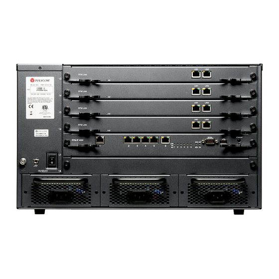
Virtual Edition Administrator Guide, LAN Redundancy and Multiple Network Services. Connect Cables to the RTM ISDN Card RTM ISDN cards come in two versions: 12 PRI ports, 1 LAN port version, and 9 PRI ports, 4 LAN ports version. The cabling for these two versions are different. Polycom, Inc. - Page 37 To connect cables to the 9 PRI ports, 4 LAN ports RTM ISDN card: Procedure 1. Connect the E1/T1 cables to PRI. 2. In MPMRx card mode, connect the LAN cable to LAN1 and LAN 2. RealPresence Collaboration Server (RMX) 4000 rear panel with AC powers and communication cables Polycom, Inc.
-
Page 38: Component Slot Allocation
AC Power Supply An RMX with AC power has three power supplies installed. A 3rd power supply is redundant (n+1). Note: Not used with DC powered systems. DC powered systems receive Direct Current from the DC PEM. Fan Drawer Mandatory Polycom, Inc. - Page 39 2nd redundant. The center slot (#20) on the rear of the RMX 4000 is disabled and is fitted with blank panel. Note: Protective bonding conductor size is 14AWG (1.5mm) within the Power Entry Model. Polycom, Inc.
-
Page 40: Realpresence Collaboration Server (Rmx) 4000 Front Panel
RMX 4000 AC front view The figure below shows the front panel of the RMX 4000 fitted with AC Power supplies. RMX 4000 DC front view The figure below shows the front panel of the RMX 4000 fitted with DC Power supplies. Polycom, Inc. - Page 41 Fan Drawer Eight fans are mounted sideways and stacked in a drawer. The drawer is connected to the Back-plane by a connector. Airflow is from right to left, and out the side of the MCU. Polycom, Inc.
-
Page 42: Rmx 4000 Front Panel Leds
G.719 audio algorithm is not supported with MPMRx cards. RMX 4000 Front Panel LEDs RMX 4000 Front Panel LEDs The following items appear on the RMX 4000 front panel. Component LED ID LED Color Description Fan Status Green Warning-Fan or power failure. Polycom, Inc. - Page 43 Card Insertion Initiated-If during the startup phase the blue HS LED remains lit, please ensure that the card is properly seated in the chassis. If this problem persists, contact your next level of support. Polycom, Inc.
-
Page 44: Replace The Cntl 4000 Module
1. Unscrew the captive screws on the front panel of the CNTL 4000 Module that secure the module to the chassis. 2. Use the metal ejector lever to pull the CNTL 4000 Module out of its slot in the backplane. 3. Carefully slide the CNTL 4000 module out through the front panel. Polycom, Inc. -
Page 45: Replace The Ac Power Supply Module
2. Using your right hand, press your thumb on the pressure latch and with your fingers inserted in the hand grip (on top), pull the power supply unit out. 3. Carefully slide the power supply unit out from the front panel. Polycom, Inc. -
Page 46: Replace The Fan Drawer
1. Unscrew the captive screws on the front panel of the fan drawer secured to the fan chassis. 2. Use the finger grip, pull the fan drawer out of its slot in the backplane. 3. Carefully slide the Fan drawer out through the front panel. Polycom, Inc. -
Page 47: Insert An Air Filter In The Fan Drawer
2. Use the finger grip, pull the Fan drawer out of its slot in the Backplane. 3. Carefully slide the Fan drawer out through the front panel. 4. Open the filter tray, by unscrewing two screws on the tray. Polycom, Inc. -
Page 48: Remove A Faulty Mpmrx Card
A fault is generated on the system. ▪ For each disconnected participant, a participant disconnection event is written to the CDR with the disconnection cause Disconnected by Operator. ▪ New participant connections are blocked when the card is removed. Polycom, Inc. -
Page 49: Install The Mpmrx Card
The card resources are added to the system resources list. ▪ The number of available resources on the RMX is usually increased to the current CFS license level. ▪ Port usage is recalculated and the Port Gauges and Video/Voice Port Configuration are updated Polycom, Inc. -
Page 50: Replace The Fabric Switch Module (Fsm 4000)
8. Ensure that the metal ejector levers are fully retracted into their housings. 9. Tighten the captive screws on the rear panel of the RMX 4000 that secure the Fabric Switch Module (FSM 4000). 10. Turn ON the RMX 4000. Polycom, Inc. -
Page 51: Realpresence Collaboration Server (Rmx) 4000 Rear Panel
RMX 4000 AC Rear View The figure below shows the rear panel of the RMX 4000 fitted with AC Power supplies. RMX 4000 DC Rear View The figure below shows the front panel of the RMX 4000 fitted with DC Power supplies. Polycom, Inc. -
Page 52: Rtm Ip 4000 Card
Do not remove the protective plastic caps from LAN 1, LAN 4 and LAN 5 ports. RMX 4000 RTM IP rear panel The following table lists the components on the RTM IP 4000 card: RTM IP 4000 Card Component Description Polycom, Inc. -
Page 53: Rtm Ip 4000 Card Led
RTM IP 4000 Card LEDs The following LEDs appear on the RTM IP 4000 card. Component LED Name LED Color Description LAN 1 Green ON with an active network connection, flickers with Packet activity. Green ON with a 1Gb online connection. Polycom, Inc. -
Page 54: Replace The Rtm Ip Rmx 4000 Card
Replace the RTM IP RMX 4000 Card The RTM IP 4000 card on the rear of the RMX 4000 provides connectivity to all the MCU modules. RTM IP 4000 connections require Ferrite cables when connecting to MPMRx cards. Polycom, Inc. -
Page 55: Rtm Isdn Card
In an RMX 4000 with at least two MPMRx cards, the RTM ISDN card can be installed in any of two rear panel card slots. Up to two RTM ISDN cards can be installed in one RMX 4000. ▪ RTM ISDN card-12 PRI ports, 1 LAN port Polycom, Inc. -
Page 56: Rtm Isdn Card-12 Pri Ports, 1 Lan Port
ON when 1Gb connection is online, flickers with packet activity. Green ON with an active network connection, flickers with packet activity. Span x not in use. Green Span x is OK. Span x red alarm (LOS - Loss of Signal) Polycom, Inc. -
Page 57: Rtm Isdn Card-9 Pri Ports, 4 Lan Ports
One DBG port: Debug port, for technician or field support use. ▪ ARM/CM switch: ARM/CM is a switch for technician or field support use. The switch decides the output source between CM or DSP UART for DBG port. Polycom, Inc. -
Page 58: Rtm Isdn Card Led-9 Pri Ports, 4 Lan Ports
When removing a card, use the metal ejector levers to pull the RTM ISDN card out of its slot from the backplane. 2. Slide out the RTM ISDN card. Install a RTM ISDN card To install a RTM ISDN card: Polycom, Inc. -
Page 59: Rtm Lan Card
The RTM LAN card routes data between the MPMRx cards and components of the system, and sends media by IP packets and provides connectivity to external IP networks. RTM LAN card-4 LAN ports Picture below shows the RTM LAN card-4 LAN ports rear panel layout. Polycom, Inc. -
Page 60: Rtm Lan Card Led-4 Lan Ports
IP packets and provides connectivity to external IP networks. RTM LAN card-2 LAN ports Picture below shows the RTM LAN card-2 LAN ports rear panel layout. Ports on the two ports RTM LAN card are two 1Gb LAN ports No. 1-2 Polycom, Inc. -
Page 61: Rtm Lan Card Led-2 Lan Ports
2. Unscrew the captive screws on the rear panel of the RMX 4000 that secure the RTM LAN card. 3. Use the metal ejector levers to pull the card out of its slot. 4. Carefully slide the RTM LAN card out through the rear panel. Polycom, Inc. -
Page 62: Install The Rtm Lan Card
Green ON-Power input is within required voltage specifications: -38.5V to -70V Not lit OFF-No LED indication, Power supply or power failure. POLARITY Polarity Error. Switch the polarity of the two ERROR cables connected to the DC power supply! Polycom, Inc. -
Page 63: Pin Assignment
The figure and table below show the pin assignment of Serial port on the RTM IP 4000 card. DB-9 connector terminated serial cable is used for connecting the port. Serial Port Pin Assignment Signal Name Description No Connection Receive Data Transmit Data No Connection Ground No Connection No Connection No Connection No Connection Polycom, Inc. - Page 64 The figure and table below show the pin assignment of LAN ports 2-6 on the RTM IP 4000 card. RJ45 connector terminated cable is used for connecting the ports. LAN Ports 2 to 6 Pin Assignment Signal Name Description Transmit Data+ Transmit Data- Receive Data+ No Connection Polycom, Inc.
-
Page 65: Pin Assignment Of Ports On The Rtm Isdn Card
Transmit Tip No Connection No Connection No Connection LAN Port Pin Assignment The figure and table below show the pin assignment of LAN ports on the RTM ISDN card. RJ45 connector terminated cable is used for connecting the port. Polycom, Inc. - Page 66 ISDN card - 9 PRI ports, 4 LAN ports. RJ45 connector terminated serial cable is used for connecting for this port. DBG (Debug) Port Pin Assignment Signal Name Description No Connection No Connection No Connection Ground Receive Data Transmit Data Polycom, Inc.
-
Page 67: Pin Assignment Of Ports On The Rtm Lan Card
DBG (Debug) Port Pin Assignment The figure and table below show the pin assignment of DBG, the serial (Debug) port on the RTM LAN card - 4 LAN ports. RJ45 connector terminated serial cable is used for connecting the port. Polycom, Inc. - Page 68 Pin Assignment DBG (Debug) Port Pin Assignment Signal Name Description No Connection No Connection No Connection Ground Receive Data Transmit Data No Connection No Connection Related Links RTM LAN Card on page 52 Polycom, Inc.
Need help?
Do you have a question about the RealPresence RMX 4000 and is the answer not in the manual?
Questions and answers