Polycom 2000 Hardware Manual
Realpresence collaboration server
Hide thumbs
Also See for 2000:
- Administrator's manual (312 pages) ,
- Getting started manual (134 pages) ,
- Hardware manual (69 pages)
Table of Contents
Advertisement
Quick Links
Download this manual
See also:
Administrator's Manual
Advertisement
Table of Contents

Subscribe to Our Youtube Channel
Related Manuals for Polycom 2000


Summary of Contents for Polycom 2000
- Page 1 Hardware Guide Version 8.3 | January 2014 | DOC2750A RealPresence Collaboration Server (RMX) 2000...
-
Page 2: Patent Information
As between the parties, Polycom, Inc., retains title to and ownership of all proprietary rights with respect to the software contained within its products. The software is protected by United States copyright laws and international treaty provision. - Page 3 Installation of this equipment must comply with local and national electrical codes. Environmental This product is compliant with the requirements of the recast RoHS Directive 2011/65/EU. Information can be obtained from Polycom Ltd, 270 Bath Road, Slough, Berkshire, SL1 4DX, UK or via: RoHSinformation@polycom.com Information on recycling can be found at: www.polycom.com/WEEE...
- Page 4 2. This device must accept any interference received, including interference that may cause undesired operation. Modifications: Any modifications made to this device that are not approved by Polycom, Inc. may void the authority granted to the user by the FCC to operate this equipment.
- Page 5 Härmed intygar Polycom (UK) Ltd att denna Polycom RMX står I överensstämmelse med de väsentliga egenskapskrav och övriga relevanta bestämmelser som framgår av direktiv 1999/5/EG. A full copy of the Declaration of Conformity can be obtained from Polycom Ltd, 270 Bath Road, Slough, Berkshire, SL1 4DX, UK. Polycom, Inc.
- Page 6 Polycom RealPresence Collaboration Server (RMX) 2000 Hardware Guide China CCC EMC statement 警告 此为 A 级产品,在生活环境中,该产品可能会造成无线电干扰。在这种情况下,可能需要用户对干 扰采取切实可 行的措施。 Taiwan BSMI EMC statement Japan VCCI EMC statement This is a Class A product based on the standard of the Voluntary Control Council for Interference by Information Technology Equipment (VCCI).
- Page 7 If trouble is experienced with this equipment, for repair or warranty information, please contact Polycom Inc in the U.S.A. 1-888-248-8294. If the equipment is causing harm to the telephone network, the telephone company may request that you disconnect the equipment until the problem is resolved.
-
Page 8: Table Of Contents
Other Rack Installation Options ......... 25 RealPresence Collaboration Server (RMX) 2000 Components ..... . . 27 RealPresence Collaboration Server (RMX) 2000 Front Panel . - Page 9 System Information Changes ......... . . 34 RealPresence Collaboration Server (RMX) 2000 LEDs ......36 Front Panel LEDs .
-
Page 10: Realpresence Collaboration Server (Rmx) 2000 Hardware Description
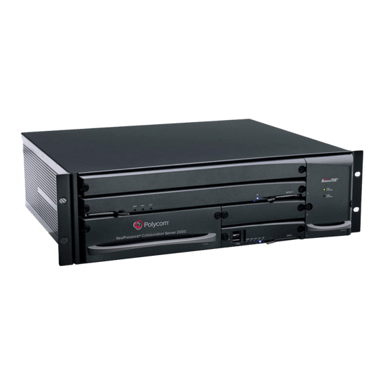
RealPresence Collaboration Server (RMX) 2000 Hardware Description This Hardware Guide provides information on the RealPresence Collaboration Server (RMX) 2000 and its components. This system utilizes a modular “universal slot” platform, whose components are designed for high performance, capacity, and reliance. -
Page 11: Realpresence Collaboration Server (Rmx) 2000 System Specifications
15.74” (40 cm.) Weight Up to 16.5 Kg (36.38 lbs.) Media Protocols Audio G.711a/u, G.722, G.722.1C, G.722.1, G.723.1, G.719 G.729A, Polycom Siren™ 14, Siren 22 (in mono or stereo) and Siren LPR. Video H.261, H.263, H.264, H.264 High Profile Network Interfaces IP, ISDN, PSTN and LAN H.323, SIP, ISDN, PSTN, VoIP, and LAN... -
Page 12: Realpresence Collaboration Server (Rmx) 2000 System Capacities
RealPresence®Collaboration Server (RMX) 2000 Hardware Guide RealPresence Collaboration Server (RMX) 2000 System Capacities Conferencing Capacities The following table summarizes the different conferencing capacities. RMX 2000 System Functions and Capacities System Functions MPMx MPMRx Maximum number of Video participants in a conference... -
Page 13: Mpmx Resource Capacities
RealPresence®Collaboration Server (RMX) 2000 Hardware Guide RealPresence Collaboration Server (RMX) 2000 System Capacities Conferencing Capacities The following table summarizes the different conferencing capacities. RMX 2000 System Functions and Capacities System Functions MPMx MPMRx Maximum number of Users Maximum number of Gateway Profiles... - Page 14 RealPresence®Collaboration Server (RMX) 2000 Hardware Guide The following table summarizes the resource capacities for a fully loaded system per card type per line rate in VSW conferencing mode. MPMx Resource Capacities per Line Rate in VSW Conferencing Mode Resource Type and Line Rate...
-
Page 15: Mpmrx Resource Capacities
The following sections list the resource capacities of the RMX 2000. MPMRx Resource Capacities in Video Switching (VSW) Conferences The table below lists the maximum resource capacities of RMX 2000 per line rate in VSW conferences (line rate being the deciding factor) when used with MPMRx cards. -
Page 16: Resource Capacities In Cp And Svc Mixed Conferences
RealPresence®Collaboration Server (RMX) 2000 Hardware Guide Licensed AVC SD AVC CIF Audio ports HD1080p60 HD1080p30 HD720p30 MPMRx-S Non-Mixed Port Resource Capacities The following table lists the system capacities for each license in non-mixed conferences. Licensed Capacity for Systems with MPMRx-S card, Non-Mixed Conferences... - Page 17 RealPresence®Collaboration Server (RMX) 2000 Hardware Guide When the required resource is not a whole number, it’s rounded up to the nearest whole number. For example, to make an SVC call requiring1/3 of an HD720p30 port. However in the Port Gauge, one port appears allocated.
-
Page 18: Total Resource Capacities Per Mpmrx-D Card In Cp & Svc Conferences
The RMX system allocates port resources in AVC HD720p30 units. The number of ports used for each types of calls differs between AVC-SVC mixed conferences and non-mixed conferences. The table below lists the maximum resource capacities of the RMX 2000 per resolution in CP Conferencing and SVC modes when used with MPMRx-D card. -
Page 19: Safety Requirements
● Place the RMX 2000 on a hard, flat surface such as a desktop or mount it on 19” rack. ● The airflow of the RMX 2000 is from right to left. Be sure that the areas in the left and right side of the system are clear for proper ventilation. -
Page 20: Installing The Realpresence Collaboration Server (Rmx) 2000
Observe the following procedures when unpacking the RMX 2000. To unpack and lift the RMX 2000: 1 When you receive the RMX 2000 packing case, inspect the equipment for damage and verify that the components match the packing slip. 2 Open the top cover of the packing case. -
Page 21: Installing The Rtm Isdn Card On The Realpresence Collaboration Server
(RMX) 2000 The ISDN card is shipped out of the box and must be manually installed into the rear of the RMX 2000. This card must be seated opposite an MPMx/MPMRx card. It is recommended that the ISDN card be installed before the RMX 2000 is placed in a rack. -
Page 22: Telescopic Rail Runner Assembly
RealPresence®Collaboration Server (RMX) 2000 Hardware Guide Rail Runners Kit Contents Part/Kit no. Item Item Item Sample Item Quantity Rack spacer assembly kit Rack spacer Front & Rear Flat head screw - M5*10mm Rail runner assembly kit Flat head screw - M3*8mm... - Page 23 Detail of Front Rack Spacer Assembly (left rail runner is shown here) On the RMX 2000 the top hole on the Rack Spacer must be left clear as it is required for fixing the RMX to the rack post.
- Page 24 3 Adjust the telescopic rack rail runner to the rack opening and mount it onto the marked position of the rear post as described in Step 2. Detail of Rear RMX 2000 Rack Spacer Assembly 4 Repeat Steps 2 and 3 for the right rack rail runner.
-
Page 25: Other Rack Installation Options
There are two other methods for installing the RMX in a 19” rack: ● Using rack brackets on the RMX 2000 Install rack brackets, supplied by the rack manufacturer, in the rack. Mount the RMX 2000 on top of the rack brackets. - Page 26 RealPresence®Collaboration Server (RMX) 2000 Hardware Guide ● Using a shelf Install the shelf, supplied by the rack manufacturer, in the rack. Mount the RMX on the shelf. Fasten the RMX to the rack with screws through the four holes in the RMX’s frRMX in rack 2ont mounting brackets.
-
Page 27: Realpresence Collaboration Server (Rmx) 2000 Components
On the RMX 2000 components are located on both the front and rear of the MCU. Please verify the type of chassis used on your RMX 2000. Starting with version 4.0, a new environmentally friendly RMX 2000 chassis is in use. For more information, contact your next level of support. -
Page 28: Realpresence Collaboration Server (Rmx) 2000 Rear Panel
The RMX 2000 rear panel contains the RTM IP card and optionally, the RTM LAN and RTM ISDN card. The RTM IP card must be located on the bottom slot in the rear of the RMX 2000. In addition, the rear panel houses the main power switch, AC inlet, a circuit breaker, and additional communications ports. - Page 29 RealPresence Collaboration Server (RMX) 1500/1800/2000/4000 Administrators Guide Administrator’s Guide, LAN Redundancy Multiple Network Services . RMX 2000 RTM IP Rear Panel Layout The following items appear on the RMX 2000 rear panel. RMX 2000 Rear Panel - RTM IP Component Description Item Description LAN 1 NA - Disconnected.
-
Page 30: Rtm Isdn
RMX with two MPMx/MPMRx cards – the RTM ISDN card can be installed in either of the two rear panel card slots. Up to two RTM ISDN cards can be installed in one RMX 2000. Up to a total of 14 E1 or 18 T1 PRI cables can be installed with two MPMx/MPMRx and RTM ISDN cards. -
Page 31: Rtm Lan Card - With 4 Lan Ports
On the RMX 2000 with MPMx card(s), the RTM LAN card(s) is optional. The RTM LAN card with four 1 GB ports is required on the RMX 2000 when MPMRx cards are installed on the system. An RTM LAN card must connect directly to an MPMx/MPMRx card. In an RMX with a single MPMx/MPMRx card, the RTM LAN card must be installed in the rear panel slot at the top slot at the same level as the MPMx/MPMRx card. -
Page 32: Connecting Cables To The Realpresence Collaboration Server (Rmx) 2000
● Required. On the RTM IP card connect the LAN cable to LAN 2 Port. ● Required*. When an RTM LAN - 4 port card is installed on the RMX 2000, connect the LAN cable to LAN 2*. •... -
Page 33: Mpmx And Mpmrx Media Cards
An RTM LAN type card is always required with Multiple Networks and LAN Redundancy configurations. ● Optional. When an RTM ISDN card is installed on the RMX 2000, connect the E1/T1 Cables to PRI Ports. RMX 2000 Rear Panel View with Cables Do not remove the protective caps from LAN1*, LAN 3 and ShMG ports on the RTM IP card. -
Page 34: Mpmx And Mpmrx Modes
RealPresence®Collaboration Server (RMX) 2000 Hardware Guide MPMx and MPMRx Modes MPMx and MPMRx cards installed in the system cannot be used simultaneously. The card type installed in the system determines the Card Configuration Mode. Therefore, the RMX can operate in either MPMx or MPMRx mode. - Page 35 RealPresence®Collaboration Server (RMX) 2000 Hardware Guide After System Reset ● The Card Configuration Mode is MPMRx. ● The inserted MPMRx card is enabled. Example 2: Current status ● An RMX has one MPMx card installed. ● The Card Configuration Mode is MPMx and the MPMx card is enabled.
-
Page 36: Realpresence Collaboration Server (Rmx) 2000 Leds
The LEDs on the rear panel indicate the state of the external connections and the status of the RTM IP card. Front Panel LEDs The following items appear on the RMX 2000 front panel. RMX 2000 Front Panel LEDs Component... -
Page 37: Realpresence Collaboration Server (Rmx) 2000 Rear Panel Leds
MPM/MPM+/MPMx’s cards HS LED. OFF - Normal ON - CPU may be removed. RealPresence Collaboration Server (RMX) 2000 Rear Panel LEDs RTM IP Card The following LEDs appear on the RTM IP card. RMX 2000 Front Panel LEDs... -
Page 38: Rtm Isdn Card
RealPresence®Collaboration Server (RMX) 2000 Hardware Guide RMX 2000 Front Panel LEDs Component LED Name LED Color Description SLOT (1-4) LEDs 1Gb (1-4) Amber ON with a 1Gb online connection, flickers with Packet activity. LNK (1-4) Green ON with an active network connection, flickers with Packet activity. -
Page 39: Rtm Lan Leds - With 4 Lan Ports
RealPresence®Collaboration Server (RMX) 2000 Hardware Guide - with 4 LAN Ports RTM LAN LEDs The following LEDs appear on the RTM LAN - 4 ports: Function Name LED Name LED Color Description LAN 1-4 LEDs 1 Gb Amber ON when 1Gb connection is online, flickers with Packet activity. -
Page 40: Rmx Chassis Types
D or E in the Part Number) is required for use with MPMx/MPMRx card(s). The chassis type can be viewed in the Hardware Monitor, by clicking Hardware Monitor and selecting Properties. The RMX 2000 - General Information dialog box opens. Polycom, Inc. -
Page 41: Component Replacement
RealPresence®Collaboration Server (RMX) 2000 Hardware Guide Component Replacement The RMX 2000 is designed with ease of maintenance in mind. Most components are swappable and are accessible directly via the front panel or the rear panel. Only MPMx/MPMRx cards are Hot Swappable. The RTM IP and RTM ISDN card are not Hot Swappable. -
Page 42: Using The Modified Pmc Compatible Ejector Lever
RealPresence®Collaboration Server (RMX) 2000 Hardware Guide Once the removal sequence is initiated and the HS LED flashes, the process cannot be terminated when activated. ● Fully Open - The card is released from the MCU housing Using the Modified PMC Compatible Ejector Lever On the RMX 4000 most components are fitted with identical ejector levers that are used to release or fasten the components to their slot. -
Page 43: Replacing The Cntl Module
A single supply unit powers the RMX 2000. Use the following procedure to replace a Power Supply. Please verify the type of power supply used on your RMX 2000. Do not insert a different type of power supply than the current type installed on your system. -
Page 44: Replacing The Fan Drawer
RealPresence®Collaboration Server (RMX) 2000 Hardware Guide To replace the Power Supply Module: 1 Ensure that the power switch on the RMX 2000 is turned OFF (O) and that the power cords are disconnected from the MCU. 2 Unscrew the captive screws on the front panel of the RMX 2000 that secure the Power Supply unit. -
Page 45: Replacing A Faulty Mpmx/Mpmrx Card
5 Push the Fan drawer firmly into the Backplane, making sure it is properly seated in its slot. 6 Tighten the captive screws on the front panel of the RMX 2000 that secure the Fan drawer. Replacing a Faulty MPMx/MPMRx Card All MPMx/MPMRx cards can be installed or removed while the RMX 2000 is powered on and operating. -
Page 46: Installing The Replacement Mpmx/Mpmrx Card
If only one media card is installed in the system, it must be inserted in the top slot of the RMX chassis. To install a new MPMx/MPMRx card in a powered on RMX 2000: 1 If applicable, loosen the captive screws and remove the slot cover. -
Page 47: Replacing The Rtm Ip Card
The green RDY LED on the MPMx/MPMRx card switches on and remains lit. Replacing the RTM IP Card The RTM IP card on the rear of the RMX 2000 provides connectivity to all the MCU modules. Use the following procedure to replace the RTM IP card. -
Page 48: Removing The Blank Cover From The Rear Panel
To remove an existing RTM ISDN card: 1 Ensure that the power switch on the RMX 2000 is turned OFF (O). 2 Unscrew the captive screws that fasten the card to the MCU. Use the metal ejector levers to pull the card out of its slot from the backplane. -
Page 49: Installing A New Or Replacement Rtm Isdn Card
RealPresence®Collaboration Server (RMX) 2000 Hardware Guide Installing a New or Replacement RTM ISDN Card Carry out the following procedure to install a new RTM ISDN card or replace an existing one. To install a new or replacement RTM ISDN card: 1 On the new RTM ISDN card move the ejector levers to their fully open position.Slide in the RTM... -
Page 50: Installing Or Replacing The Rtm Lan
Installing or Replacing the RTM LAN The RTM LAN card on the rear of the RMX 2000 provides connectivity to all the MCU modules. The RTM LAN card must be seated opposite to an MPMx/MPMRx card located in the top slots on the front of the RMX. -
Page 51: Inserting The Rtm Lan (With 4 Lan Ports) To Its Slot
3 Push the RTM LAN card firmly into the backplane, making sure it is properly seated in its slots. 4 Ensure that the metal ejector levers are fully retracted into their housings. 5 Tighten the captive screws on the rear panel of the RMX 2000 that secure the RTM LAN card. 6 Reconnect the cables. -
Page 52: Pri Port Assignment
PRI Port Assignment Signal Name Receive Ring Receive Tip No connection Transmit Ring Transmit Tip No connection No connection No connection Polycom, Inc.
Need help?
Do you have a question about the 2000 and is the answer not in the manual?
Questions and answers