Polycom RMX 2000 Hardware Manual
Realpresence collaboration
server (rmx) 2000
Hide thumbs
Also See for RMX 2000:
- Administrator's manual (312 pages) ,
- Getting started manual (134 pages) ,
- Hardware manual (52 pages)
Table of Contents
Advertisement
Quick Links
Download this manual
See also:
Administrator's Manual
Advertisement
Table of Contents

Subscribe to Our Youtube Channel
Related Manuals for Polycom RMX 2000


Summary of Contents for Polycom RMX 2000
- Page 1 HARDWARE GUIDE Version 8.6 | June 2015 | 3725-74521-000A ® RealPresence Collaboration ® Server (RMX ) 2000...
- Page 2 Polycom up to three (3) years after the distribution date of the applicable product or software at a charge not greater than the cost to Polycom of shipping or distributing the software to you. To receive software information, as well as the open source software code used in this product, contact Polycom by email at OpenSourceVideo@polycom.com.
- Page 3 Installation of this equipment must comply with local and national electrical codes. Environmental This product is compliant with the requirements of the recast RoHS Directive 2011/65/EU. Information can be obtained from Polycom Ltd, 270 Bath Road, Slough, Berkshire, SL1 4DX, UK or via: RoHSinformation@polycom.com Information on recycling can be found at: www.polycom.com/WEEE...
- Page 4 2. This device must accept any interference received, including interference that may cause undesired operation. Modifications: Any modifications made to this device that are not approved by Polycom, Inc. may void the authority granted to the user by the FCC to operate this equipment.
- Page 5 Härmed intygar Polycom (UK) Ltd att denna Polycom RMX står I överensstämmelse med de väsentliga egenskapskrav och övriga relevanta bestämmelser som framgår av direktiv 1999/5/EG. A full copy of the Declaration of Conformity can be obtained from Polycom Ltd, 270 Bath Road, Slough, Berkshire, SL1 4DX, UK. Polycom, Inc.
- Page 6 If trouble is experienced with this equipment, for repair or warranty information, please contact Polycom Inc in the U.S.A. 1-888-248-8294. If the equipment is causing harm to the telephone network, the telephone company may request that you disconnect the equipment until the problem is resolved.
-
Page 7: Table Of Contents
Replacement ............34 RealPresence Collaboration Server (RMX) 2000 Front Panel ......34 Polycom, Inc. - Page 8 Install the Replacement MPMRx Card ........55 Install a New MPMRx Card in a Powered on RMX 2000 ..... . 55 Replace the RTM IP Card .
- Page 9 DBG (Debug) Port Pin Assignment ......... . 69 Polycom, Inc.
-
Page 10: Realpresence Collaboration Server (Rmx ) 2000 Hardware Specifications
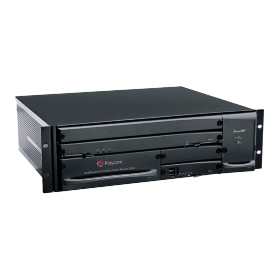
The main components on the system are: ● CNTL 2000 (CPU) Module: Controls and manages the RMX 2000 ● AC Power Supply Modules: Provides current to the RMX 2000 system ● Fan Drawer: Fans provide airflow and cools the RMX 2000 system ●... -
Page 11: Realpresence Collaboration Server (Rmx) 2000 System Specifications
15.74” (40 cm.) Weight Up to 16.5 Kg (36.38 lbs.) Media Protocols Audio G.711a/u, G.722, G.722.1C, G.722.1, G.723.1, G.719 G.729A, Polycom Siren™ 14, Siren 22 (in mono or stereo) and Siren LPR. Video H.261, H.263, H.264, H.264 High Profile Network Interfaces IP, ISDN and LAN H.323, SIP, H.320, ISDN-Voice, VoIP, and LAN... -
Page 12: Realpresence Collaboration Server (Rmx) 2000 System Capacities
(RMX) 2000 System Capacities This section provides information of conferencing capacities, MPMRx resource capacities. Conferencing Capacities The following table summarizes the different conferencing capacities. System Functions and Capacities of RMX 2000 System Functions MPMRx Maximum number of Video participants per Conference... - Page 13 RealPresence Collaboration Server (RMX) 2000 System Capacities System Functions and Capacities of RMX 2000 System Functions MPMRx Number of Participant alerts Unlimited Maximum number of concurrent RealPresence Collaboration Server Web Client connections to the MCU Maximum number Address Book entries...
-
Page 14: Mpmrx Resource Capacities
Note: Maximum RMX 2000 resource capacities with two MPMRx cards equipped This section provides per-card resource capacities. Because RMX 2000 supports a maximum of two MPMRx cards equipped, RMX 2000 resource capacities are the double the maximum of MPMRx-D resource capacities per-card in the non-mixed conferences. - Page 15 1.00 2.00 2.00 3.75 3.75 1.88 0.25 0.49 1.00 2.00 2.00 3.53 3.53 1.76 0.24 0.50 1.00 2.00 2.00 3.33 3.33 1.67 0.24 0.49 1.00 2.00 2.00 3.16 3.16 1.58 0.25 0.50 1.00 2.00 2.00 3.00 3.00 1.50 Polycom, Inc.
-
Page 16: Mpmrx-D Resource Capacities In Mixed Cp And Svc Conferences
MPMRx-D Port Resource Capacities per License Type per Conference Type Licenses 1080p60 1080p30 HD720p30 AVC SD AVC CIF Audio SVC 720p SVC 1080p The following table lists license ratios of MPMRx-D card per conference license type per conference type in CP and SVC mixed conferences. Polycom, Inc. - Page 17 0.66 1.25 1.25 1.88 1.88 1.88 0.21 0.40 0.66 1.18 1.18 1.76 1.76 1.76 0.22 0.40 0.67 1.11 1.11 1.67 1.67 1.67 0.22 0.40 0.66 1.05 1.05 1.58 1.58 1.58 0.22 0.40 0.66 1.00 1.00 1.50 1.50 1.50 Polycom, Inc.
-
Page 18: Mpmrx-S Resource Capacities In Non-Mixed Conferences
1.00 2.00 2.00 12.00 5.00 5.00 0.20 0.47 1.00 2.00 2.00 12.00 5.00 5.00 0.25 0.50 1.00 2.00 2.00 12.00 5.00 5.00 0.24 0.48 1.00 2.00 2.00 12.00 5.00 5.00 0.23 0.50 1.00 2.00 2.00 10.00 5.00 5.00 Polycom, Inc. -
Page 19: Mpmrx-S Resource Capacities In Mixed Cp And Svc Conferences
0.60 1.30 1.30 12.00 5.00 5.00 0.20 0.40 0.67 1.33 1.33 10.00 5.00 5.00 0.20 0.40 0.65 1.30 1.30 7.50 3.75 3.75 0.20 0.40 0.64 1.32 1.32 6.00 3.00 3.00 0.20 0.40 0.67 1.33 1.33 5.00 2.50 2.50 Polycom, Inc. -
Page 20: Mpmrx Resource Capacity In Vsw Conference
Older Codecs are still supported, and the port ratios and capacities are as below: ● AVC SDp60 (4CIFp60), H.263 SD, AVC CIFp60, or H.263 CIF Equals to port ratios and capacities of AVC H.264 720p30. ● H.261 CIF Equals to port ratios and capacities of AVC H.264 1080p30. Polycom, Inc. -
Page 21: Prepare For Installation
● Do not use liquids around your equipment. Rack Mount Safety Precautions The following precautions should be followed with regards to rack mount safety: ● Keep the area around the RealPresence Collaboration Server (RMX) 2000 clean and free of clutter. Polycom, Inc. -
Page 22: Installation Precautions
● Install the heaviest components on the bottom of the rack first, and then work up. ● Allow the power supply units to cool before touching them. ● Always keep the rack trays and card slots closed when not servicing, to maintain proper cooling. Polycom, Inc. -
Page 23: Unpack The Realpresence Collaboration Server (Rmx) 2000
4 Lift the RealPresence Collaboration Server from the box, and place it on a flat surface or in a rack. Remove the packaging materials prior to positioning the RealPresence Collaboration Server. Polycom, Inc. -
Page 24: Verify The Accessories Kits
Installation Accessory Kit and Rack Installation Accessories Kit. Verify that all accessories are included. Installation Accessory Kit Accessory Quantity Power cable Ethernet cable RMX 2000 Quick Installation Guide Rail Runners Kit Contents Item Item Part/Kit no. Item Item Sample... - Page 25 Rack spacer assembly kit Rack spacer Front & Rear Flat head screw - M5*10mm Rail runner assembly kit Flat head screw - M3*8mm Flat washer M3 Nut spring M3 RMX chassis assembly kit Pan head screw - M5*12mm Flat washer M5 Polycom, Inc.
-
Page 26: Install The Telescopic Rail Runner On The Rack
Front view of an RMX rail runner assembly 2 Position the rack spacer onto the marked rack post together with the left rack rail runner (1) and fasten the flat head screws as shown in the following figure. Polycom, Inc. - Page 27 Detail of front rack spacer assembly (left rail runner is shown here) Note: Top hole of the rack spacer On the RMX 2000, the top hole of the Rack Spacer must remain empty as it is required for fixing the RMX to the rack post.
- Page 28 Prepare for Installation Detail of left rail runner (front internal view) Note: Number of screws needed The number of screws you will install depends on the rack width. 6 Repeat Step 5 for the right rack rail runner. Polycom, Inc.
-
Page 29: Install The Realpresence Collaboration Server (Rmx) 2000
1 Ensure that the power switch/circuit switch on the RealPresence Collaboration Server (RMX) 2000 is turned OFF (O). 2 Unscrew the captive screws on the rear panel of the RealPresence Collaboration Server (RMX) 2000 that secure the blank panel. 3 Use the metal ejector levers to pull off the blank panel. Polycom, Inc. -
Page 30: Mount The Realpresence Collaboration Server (Rmx) 2000 In A Rack
The RealPresence Collaboration Server (RMX) 2000 must be lifted into the rack by two people. There are two methods for installing the RealPresence Collaboration Server (RMX) 2000 in a 19” rack (which must be lifted by two people): ● Using rack rail runners on the rack Polycom, Inc. - Page 31 Install the shelf, supplied by the rack manufacturer, in the rack. Mount the RealPresence Collaboration Server (RMX) 2000 on the shelf. Fasten the RealPresence Collaboration Server (RMX) 2000 to the rack with screws through the four holes in the RealPresence Collaboration Server 2000 front mounting brackets Polycom, Inc.
-
Page 32: Connect Cables To The Realpresence Collaboration Server (Rmx) 2000
Connect Cables to the RealPresence Collaboration Server (RMX) 2000 Do not remove the protective caps from LAN1, LAN3 and ShMG ports when you connect the cables to RMX 2000. Connect the following cables to the back panel: ● Required. Power cable. - Page 33 Install the RealPresence Collaboration Server (RMX) 2000 RealPresence Collaboration Server (RMX) 2000 rear panel view with cables-MPMRx card(s) Polycom, Inc.
-
Page 34: Realpresence Collaboration Server (Rmx) 2000 Components And Components Replacement
MCU. Note: Chassis types Please verify the type of chassis used on your RMX 2000. Starting with version 4.0, a new environmentally friendly RMX 2000 chassis is in use. For more information, contact your next level of support. - Page 35 Multi Processor Module The MPMRx cards, perform the various RTP, audio and video processing (MPMRx) Card functions on the RMX 2000 unit. TI processors are at the core of each MPMRx card which are available in two assemblies: • MPMRx -S •...
-
Page 36: Realpresence Collaboration Server (Rmx) 2000 Rear Panel
The RMX 2000 rear panel contains the RTM IP card and, optionally, the RTM LAN and RTM ISDN card. The RTM IP card must be located in the bottom slot in the rear of the RMX 2000. In addition, the rear panel houses the main power switch, AC inlet, a circuit breaker, and additional communications ports. -
Page 37: Rtm Isdn Card
RealPresence Collaboration Server (RMX) 2000 Components and Components Replacement RMX 2000 Rear Panel - RTM IP Component Description Item Description LAN 3 For Remote Access only using the Alternate Management Network. For more information, see Appendix G in the RealPresence Collaboration Server (RMX) 1800/2000/4000 Administrator’s Guide. - Page 38 Any PRI port can work as either E1 or T1 port, and each ISDN card can support up to 7 E1 or 9 T1 ports. With two ISDN cards equipped, a total of 14 E1 or 18 T1 ports can be used for connecting external ISDN networks. Polycom, Inc.
-
Page 39: Rtm Lan Card
MPMRx cards are installed on the system. An RTM LAN card must connect directly to an MPMRx card. In an RealPresence Collaboration Server (RMX) 2000 with a single MPMRx card, the RTM LAN card must be installed in the rear panel slot at the top slot at the same level as the MPMRx card. Polycom, Inc. - Page 40 An RTM LAN card must connect directly to an MPMRx card. In an RMX with a single MPMRx card, the RTM LAN card must be installed in the top slot rear panel slot at the same level as the MPMRx card. The RTM LAN card with two LAN ports is shown next: Polycom, Inc.
- Page 41 RealPresence Collaboration Server (RMX) 2000 Components and Components Replacement RTM LAN Card - two LAN ports Two 1Gb LAN ports No. 1-2 are on this RTM LAN card. For pin assignment information, see Pin Assignment of Ports on the RTM LAN Card Polycom, Inc.
-
Page 42: Realpresence Collaboration Server (Rmx) 2000 Leds
On the front panel, the LEDs reflect the state of the components. The LEDs on the rear panel indicate the state of the external connections and the status of the RTM IP card. Front Panel LEDs The following items appear on the RMX 2000 front panel. RMX 2000 Front Panel LEDs Component... - Page 43 RealPresence Collaboration Server (RMX) 2000 Components and Components Replacement RMX 2000 Front Panel LEDs (continued) Component LED ID LED Color Description CNTL Unit ON - Major system error. In case of an active alarm this light is ON, and the RDY green is OFF.
-
Page 44: Realpresence Collaboration Server (Rmx) 2000 Rear Panel Leds
(red) button in the Hardware Monitor tool bar, the system should enter a standby mode and the LED turns ON. Only the media and control unit cards are in a standby mode. Shelf Manager remains active. Turn the system OFF/ON to exit the standby mode. Polycom, Inc. -
Page 45: Rtm Isdn Card - 12 Pri Ports, One Lan Port
Span x red alarm. (LOS - Loss of Signal) LAN 1-4 - 1 Gb Amber ON when 1Gb connection is online, flickers with Packet activity. LAN 1-4 - LNK Green ON with an active network connection, flickers with Packet activity. Polycom, Inc. -
Page 46: Rtm Lan Leds - Four Lan Ports
The following LEDs appear on the two ports RTM LAN card: RTM LAN LEDs Function Name LED Name LED Color Description LAN 1-2 1 Gb Green ON when 1Gb connection is online, flickers with Packet activity. Amber ON with an active network connection, flickers with Packet activity. Polycom, Inc. - Page 47 LED Name LED Color Description Blue OFF - Normal. Flashes - During the startup of a media card and control unit. Also flashes when the RTM LAN card is powered down. ON - RTM LAN card may be removed. Polycom, Inc.
-
Page 48: Realpresence Collaboration Server (Rmx) Chassis Types
D or E-type chassis (indicated by the letter D or E in the Part Number) is required for use with MPMRx card(s). The chassis types can be viewed by clicking Hardware Monitor > Properties. The RealPresence Collaboration Server (RMX) 2000 General Info dialog box opens. Polycom, Inc. -
Page 49: Component Replacement
If this problem persists, contact your next level of support. Use the PMC Compatible Ejector Lever On the RMX 2000 most components are fitted with identical ejector levers that are used to release or fasten the components to their slot. - Page 50 Once the removal sequence is initiated the process cannot be terminated, and the HS led flashes when activated. ● Closing the Lever - With your thumb on the handle (2), press the lever against the panel until it clicks into place. Polycom, Inc.
-
Page 51: Replace The Cntl Module
1 Ensure that power switch on the RMX 2000 is turned OFF (O). 2 Unscrew the captive screws on the front panel of the RMX 2000 that secure the CNTL Module. 3 Use the metal ejector lever to pull the CNTL Module out of its slot in the Backplane. -
Page 52: Replace The Power Supply Module
To replace the Power Supply Module: 1 Ensure that the power switch on the RMX 2000 is turned OFF (O) and that the power cords are disconnected from the MCU. -
Page 53: Replace The Fan Drawer
4 Slide in the replacement Fan drawer. 5 Push the Fan drawer firmly into the Backplane, making sure it is properly seated in its slot. 6 Tighten the captive screws on the front panel of the RMX 2000 that secure the Fan drawer. Polycom, Inc. -
Page 54: Replace A Faulty Mpmrx Card
Replace a Faulty MPMRx Card All MPMRx cards can be installed or removed while the RMX 2000 is powered on and operating. Prior to removing an MPMRx card the captive screws must be unscrewed and the ejector levers must be opened to initiate a “power down”... -
Page 55: Install The Replacement Mpmrx Card
If only one media card is installed in the system, it must be inserted in the top slot of the RMX chassis. To install a new MPMRx card in a powered on RMX 2000: 1 If applicable, loosen the captive screws and remove the slot cover. -
Page 56: Replace The Rtm Ip Card
RealPresence Collaboration Server (RMX) 2000 Components and Components Replacement Replace the RTM IP Card The RTM IP card on the rear of the RMX 2000 provides connectivity to all the MCU modules. Use the following procedure to replace the RTM IP card. -
Page 57: Remove The Blank Cover From The Rear Panel
To remove the blank cover from a rear panel: 1 Ensure that the power switch/circuit switch on the RMX is turned OFF (O). 2 Unscrew the captive screws on the rear panel of the RMX that secure the blank panel. Polycom, Inc. -
Page 58: Install Or Replace The Rtm Isdn Card
To remove an existing RTM ISDN card: 1 Ensure that the power switch on the RMX 2000 is turned OFF (O). 2 Unscrew the captive screws that fasten the card to the MCU. Use the metal ejector levers to pull the card out of its slot from the backplane. - Page 59 ● Update your licence. For more information see First Entry Power-up and Configuration in the RealPresence Collaboration Server (RMX) 1800/2000/4000 Getting Started Guide. ● In the ISDN Network Services define a New ISDN Network Service. For more information, see Adding/Modifying ISDN Network Services in the RealPresence Collaboration Server (RMX) 1800/2000/4000 Administrator’s Guide. Polycom, Inc.
-
Page 60: Install Or Replace The Rtm Lan
Install or Replace the RTM LAN The RTM LAN card on the rear of the RMX 2000 provides connectivity to all the MCU modules. The RTM LAN card must be seated opposite to an MPMRx card located in the top slots on the front of the RMX. - Page 61 3 Push the RTM LAN card firmly into the media card, making sure it is properly seated in its slots. 4 Ensure that the metal ejector levers are fully retracted into their housings. 5 Tighten the captive screws on the rear panel of the RMX 2000 that secure the RTM LAN card. 6 Reconnect the cables.
-
Page 62: Pin Assignment
The figure and table below show the pin assignment of Serial port on the RTM IP 2000 card. DB-9 connector terminated serial cable is used for connecting the port. Serial Port Pin Assignment Signal Name Description No Connection Receive Data Transmit Data No Connection Ground No Connection No Connection No Connection No Connection Polycom, Inc. -
Page 63: Lan Ports 1-3 Pin Assignment
BI_DD- Bidirectional pair D- LAN Port ShMG Pin Assignment The figure and table below show the pin assignment of LAN port ShMG on the RTM IP 2000 card. RJ45 connector terminated cable is used for connecting the ports. Polycom, Inc. - Page 64 Pin Assignment LAN Port ShMG Pin Assignment Signal Name Description Transmit Data+ Transmit Data- Receive Data+ No Connection No Connection Receive Data- No Connection No Connection Polycom, Inc.
-
Page 65: Pin Assignment Of Ports On The Rtm Isdn Card
The figure and table below show the pin assignment of PRI ports on the RTM ISDN card. RJ45 connector terminated cable is used for connecting the ports. PRI Port Pin Assignment Signal Name Description Rx/Ring Receive Ring Rx/Tip Receive Tip No connection Tx/Ring Transmit Ring Tx/Tip Transmit Tip No connection No connection No connection Polycom, Inc. -
Page 66: Lan Port Pin Assignment
The figure and table below show the pin assignment of DBG port, the serial (Debug) port on the RTM ISDN card - 9 PRI ports, four LAN ports. RJ45 connector terminated serial cable is used for connecting for this port. Polycom, Inc. - Page 67 Pin Assignment DBG (Debug) Port Pin Assignment Signal Name Description No connection No connection No connection Ground Receive Data Transmit Data No connection No connection Polycom, Inc.
-
Page 68: Pin Assignment Of Ports On The Rtm Lan Card
LAN Ports Pin Assignment Signal Name Description BI_DA+ Bidirectional pair A+ BI_DA- Bidirectional pair A- BI_DB+ Bidirectional pair B+ BI_DB- Bidirectional pair B- BI_DC+ Bidirectional pair C+ BI_DC- Bidirectional pair C- BI_DD+ Bidirectional pair D+ BI_DD- Bidirectional pair D- Polycom, Inc. -
Page 69: Dbg (Debug) Port Pin Assignment
- four LAN ports. RJ45 connector terminated serial cable is used for connecting the port. DBG (Debug) Port Pin Assignment Signal Name Description No connection No connection No connection Ground Receive Data Transmit Data No connection No connection Polycom, Inc.
Need help?
Do you have a question about the RMX 2000 and is the answer not in the manual?
Questions and answers