
Related Manuals for Omron SYSDRIVE 3G3FV


Summary of Contents for Omron SYSDRIVE 3G3FV
- Page 1 Cat. No. I516-E1-4 USER’S MANUAL SYSDRIVE 3G3FV High-function General-purpose Inverter...
- Page 2 Thank you for choosing this SYSDRIVE 3G3FV-series product. Proper use and handling of the product will ensure proper product performance, will length product life, and may prevent possible accidents. Please read this manual thoroughly and handle and operate the product with care.
- Page 3 OMRON Product References All OMRON products are capitalized in this manual. The word “Unit” is also capitalized when it refers to an OMRON product, regardless of whether or not it appears in the proper name of the product. The abbreviation “Ch,” which appears in some displays and on some OMRON products, often means “word”...
-
Page 4: General Precautions
Make sure that these protective covers are on the product before use. Consult your OMRON representative when using the product after a long period of storage. WARNING Do not touch the inside of the Inverter. Doing so may result in electrical shock. -
Page 5: Installation Precautions
Transportation Precautions Caution Do not hold by front cover or panel , instead, hold by the radiation fin (heat sink) while transporting the product. Doing so may result in injury. Caution Do not pull on the cables. Doing so may result in damage to the product or malfunc- tion. - Page 6 Caution Install external breakers and take other safety measures against short-circuiting in external wiring. Not doing so may result in fire. Caution Confirm that the rated input voltage of the Inverter is the same as the AC power sup- ply voltage. An incorrect power supply may result in fire, injury, or malfunction. Caution Connect the Braking Resistor and Braking Resistor Unit as specified in the manual.
- Page 7 WARNING Be sure to confirm that the RUN signal is turned OFF before turning ON the power supply, resetting the alarm, or switching the LOCAL/REMOTE selector. Doing so while the RUN signal is turned ON may result in injury. Caution Be sure to confirm permissible ranges of motors and machines before operation because the Inverter speed can be easily changed from low to high.
- Page 8 Warning Labels Warning labels are pasted on the product as shown in the following illustration. Be sure to follow the instructions given there. H Warning Labels H Contents of Warning...
-
Page 9: Checking Before Unpacking
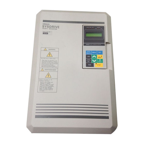
Checking Before Unpacking H Checking the Product On delivery, always check that the delivered product is the SYSDRIVE 3G3MV Inverter that you ordered. Should you find any problems with the product, immediately contact your nearest local sales representative. Checking the Nameplate Inverter model 3G3FV-A2001 Input specifications... -
Page 10: Checking The Accessories
Maximum Applicable Motor Capacity 0.4 kW 0.75 kW 1.5 kW 2.2 kW 3.7 kW 5.5 kW 7.5 kW 11 kW 15 kW 18.5 kW 22 kW 30 kW 37 kW 45 kW 55 kW 75 kW 110 kW 160 kW 185 kW 220 kW 300 kW... - Page 11 About this Manual This manual is divided into the chapters described in the following table. Information is organized by application area to enable you to use the manual more efficiently. Chapter Contents Chapter 1 Overview Describes features and nomenclature. Also describes new functions. Chapter 2 Installation Provides information required for system design, such as product dimensions, installation dimensions, peripheral device design...
- Page 12 How to Change the Digital Operator Display from Japanese to English If the Digital Operator displays messages in Japanese, change to the English mode using the following steps. (This manual provides descriptions for the English mode.) Power ON...
-
Page 13: Table Of Contents
Table of Contents Chapter 1. Introduction ........1-1 Function . - Page 14 Table of Contents 5-2 Open-loop Vector Control ........... . . 5-20 5-2-1 Auto-tuning Procedure .
- Page 15 Table of Contents 6-5 Common Functions ............6-40 6-5-1 Summary of Common Control Functions .
-
Page 16: Chapter 1. Introduction
Chapter 1 Introduction Function Nomenclature New Functions... - Page 17 Chapter 1 Introduction Functions The general-purpose SYSDRIVE 3G3FV Inverter provides full current vector control based on advanced control logic. An auto-tuning function allows for easy vector control. The Digital Operator’s display area features a 2-line by 16-character liquid crystal dis- play.
- Page 18 Chapter 1 Introduction H SYSDRIVE 3G3FV Inverter Models The following 200- and 400-V class 3G3FV Inverter models are available. A total of 21 types of Inverters are available for maximum applicable motor capacities of 0.4 to 300 kW. Voltage class...
-
Page 19: Torque Control
Chapter 1 Introduction H Selection of Modes for Vector Control and V/f Control The 3G3FV has the following four control modes. S Open-loop vector control (without PG*) [Factory default] S Flux vector control (with PG) S V/f control (without PG) S V/f control (with PG) *PG stands for “pulse generator”... -
Page 20: Pid Control
Chapter 1 Introduction Custom V/f pattern can be set. H Frequency References The following five types of frequency references can be used to control the output frequency of the Inverter. S Numeric input from the Digital Operator S Voltage input within a range from 0 to 10 V S Voltage input within a range from 0 to 10 V (With minus voltage, rotation is in the opposite direc- tion of the run command.) S Current input within a range from 4 to 20 mA... -
Page 21: Monitor Function
Chapter 1 Introduction H Dwell Function By holding the output frequency for a constant time during acceleration and deceleration, acceleration and deceleration can be performed without stepping out even when driving a motor with a large start- up load. H Low Noise (0.4- to 160-kW Models) The output transistor of the Inverter is an IGBT (insulated gate bipolar transistor). - Page 22 Chapter 1 Introduction The 3G3FV allows the following three kinds of access levels to be set in order to further simplify pa- rameter setting. (An access level is a range of parameters that can be set or referenced.) S Quick-start: Sets/reads parameters required for trial operation.
-
Page 23: Nomenclature
Chapter 1 Introduction Nomenclature H Panel Protection cover (top and bottom) Mounting hole Heat sink Digital Operator Front cover Terminals... - Page 24 Chapter 1 Introduction Terminals (with Front Cover Removed) Example: 200-V Class Inverter with 0.4-kW Output Control circuit terminals Main circuit terminals Power input Motor output Braking Resistor...
-
Page 25: Digital Operator
Chapter 1 Introduction H Digital Operator Operation Mode Indicators DRIVE: Lit when in operation mode. FWD: Lit when there is a forward command input. REV: Lit when there is a reverse command input. SEQ: Lit when the forward/reverse command from the control circuit terminal is enabled. -
Page 26: New Functions
Chapter 1 Introduction New Functions The following software versions have been implemented for the 3G3FV Series to add and upgrade functions. August 1996: Software Ver. VSG101032 (S1032) April 1997: Software Ver. VSG101040 (S1040) Sept. 1998: Software Ver. VSG101043 (S1043) Sept. 1999: Software Ver. - Page 27 Chapter 1 Introduction Parameter Settings for Second Motor (Parameters E5-01 to E5-06) Parameter settings were added so that different parameters can be set for the second motor. H Inverter Output Noise Reduction The noise output by 400-V class Inverters was reduced to reduce the affect on peripheral devices and conform to EN standards.
-
Page 28: Software Ver. Vsg101043
Chapter 1 Introduction 1-3-2 Software Ver. VSG101043 H CompoBus/D Communications Improved The following functions were added for DeviceNet communications using a CompoBus/D Communica- tions Card. Network Reference/Network Control Support (CompoBus/D Communications Remote I/O) A function was added to switch between inputting the Inverter frequency reference and a run command using CompoBus/D communications from remote I/O. -
Page 29: Software Ver. Vsg101113
Chapter 1 Introduction H Improved English Messages The English messages displayed on the Digital Operator when the language is set to English (A1-00 = 0) have been improved. 1-3-3 Software Ver. VSG101113 H Messages in 7 Languages Application as a global inverter is enabled by displays in Japanese, English, French, German, Italian, Spanish, or Portuguese. - Page 30 Chapter 1 Introduction Feedback Loss Detection for PID Control (Parameters b5-12 to b5-14) A function has been added to detect the loss of the feedback signal (e.g., as a result of line disconnec- tion) and specify the operation when an error is detected. PID Control Target Value Added to Multi-function Inputs (Parameters H3-05 and H3-09) A function was added so that both the analog frequency reference and the PID control target value can...
- Page 31 Chapter 1 Introduction H Protection Setting for Motors for Vector Control (Parameter E1-02) A special protection setting has been provided for vector-control motors, which have high resistance to overloads even at low speeds. H Bias Function for Analog Monitor Cards (Parameters F4-05 and F4-06) A bias function has been added to the analog output from Analog Monitor Cards to enable adjusting the offset voltage.
-
Page 32: Software Ver. Vsg101114
Chapter 1 Introduction New Parameter Default Setting Parameter Parameter name Applicable Previous setting New setting number Inverters range range L2-04 Voltage restart time Inverters of 0.6 s 1.0 s 55 kW or larger 1-3-4 Software Ver. VSG101114 H PG Speed Deviation Detection Function Upgrade (F1-04) This function has been changed so that the conditions can be selected for speed deviation (DEV) detec- tion. -
Page 33: Chapter 2. Installation
Chapter 2 Installation Mounting Wiring... -
Page 34: Mounting
Chapter 2 Installation Mounting 2-1-1 Dimensions H 3G3FV-A2004/-A2007/-A2015/-A2022/-A2037 3G3FV-A4004/-A4007/-A4015/-A4022/-A4037 External Dimensions Mounting Dimensions Two, 5.5 dia. Four, M5 Dimensions (mm) Voltage class Model 3G3FV- 200-V A2004/A2007/A2015 A2022/A2037 400-V A4004/A4007 A4015/A4022/A4037... - Page 35 Chapter 2 Installation H 3G3FV-A2055/-A2075/-A4055/-A4075 External Dimensions Mounting Dimensions Four, M6 Two, 7 dia. H 3G3FV-A2110/-A2150/-A4110/-A4150 External Dimensions Mounting Dimensions Two, 7 dia. Four, M6 Note *The dashed lines apply only to the A2150.
- Page 36 Chapter 2 Installation H 3G3FV-B2185/-B2220/-B4185/-B4220/-B4300/-B4450 External Dimensions Mounting Dimensions Four, M6 Voltage class Model 3G3FV- Dimensions (mm) 200-V B2185/B2220 174.5 400-V B4185/B4220 174.5 B4300/B4370/B4450...
- Page 37 Chapter 2 Installation H 3G3FV-B2300/-B2370/-B2450/-B2550/-B4550/-B4750-E External Dimensions Mounting Dimensions Two, 12 dia. Four, M10 Voltage class Model 3G3FV- Dimensions (mm) 200-V B2300B2370 B2450/B2550 400-V B4550/B4750-E 455...
- Page 38 Chapter 2 Installation H 3G3FV-B2750-E/-B411K-E/-B416K-E External Dimensions Mounting Dimensions Two, 14 dia. Four, M12 Voltage class Model 3G3FV- Dimensions (mm) 200-V B2750-E 400 max. 400-V B411K-E 375 max. B416K-E 400 max.
- Page 39 Chapter 2 Installation H 3G3FV-B418K-E/-B422K-E External Dimensions Mounting Dimensions Six, 14 dia. Six, M12 H 3G3FV-B430K-E External Dimensions Mounting Dimensions Six, 14 dia. Six, M12...
-
Page 40: Installation Conditions
Chapter 2 Installation Two, 4 dia. Panel face Panel cutout (for cables) Front side of panel Back side of panel 18.8 30 min. 2-1-2 Installation Conditions H Cautions and Warnings WARNING Provide an appropriate stopping device on the machine side to secure safety. (A holding brake is not a stopping device for securing safety.) Not doing so may result in injury. -
Page 41: Installation Site
Chapter 2 Installation H Direction and Dimensions Install the Inverter on a vertical surface so that the characters on the nameplate are oriented upward. When installing the Inverter, always provide the following installation space to allow normal heat dis- sipation from the Inverter. 120 mm min. - Page 42 Chapter 2 Installation H Protecting Inverter from Foreign Matter During Installation Place a cover over the Inverter during installation to shield it from metal power produced by drilling. Upon completion of installation, always remove the cover from the Inverter. Otherwise, ventilation will be affected, causing the Inverter to overheat.
-
Page 43: Wiring
Chapter 2 Installation Wiring H Cautions and Warnings WARNING Wiring must be performed only after confirming that the power supply has been turned OFF. Not doing so may result in electrical shock. WARNING Wiring must be performed by authorized personnel. Not doing so may result in electrical shock or fire. -
Page 44: Removing And Mounting The Front Cover . . . . . . . . . . . . . . . . . . . . . . . . . . . . . . . . . . 2-2-2 Terminals
Chapter 2 Installation 2-2-1 Removing and Mounting the Front Cover Remove the front cover to wire the terminals. Remove the Digital Operator from the front cover before removing the front cover. For models of 15 kW or less (both 200-V and 400-V class), do not remove or mount the front cover without first removing the Digital Operator;... -
Page 45: Mounting The Digital Operator
Chapter 2 Installation Mounting the Front Cover Mount the front cover to the Inverter by taking in reverse order to the steps to remove the front cover after wiring the terminals. Do not mount the front cover with the Digital Operator attached to the front cover, otherwise Digital Operator may malfunction due to imperfect contact. - Page 46 Chapter 2 Installation 2-2-2 Terminals H Terminal Block Configuration (200-V Class with 0.4-kW Output) Control circuit terminals Main circuit terminals Power input Motor output Braking Resistor 2-14...
-
Page 47: Main Circuit Terminals
Chapter 2 Installation H Main Circuit Terminals 200-V Class A2004 to A2075 A2110 to A2150 B2185 to B2220 B2300 to B2750-E Model 3G3FV- Maximum 0.4 to 7.5 kW 11 to 15 kW 18.5 to 22 kW 30 to 75 kW applied motor capacity L1 (R) - Page 48 Chapter 2 Installation 400-V Class A4004 to A4150 B4185 to B4450 B4550 to B416K-E B418K-E to Model 3G3FV- B430K-E Maximum 0.4 to 15 kW 18.5 to 45 kW 55 to 160 kW 185 to 300 kW applied motor capacity Power supply input terminals, 3-phase, 380 to 460 VAC, 50/60 Hz L1 (R) L2 (S) L3 (T)
- Page 49 Chapter 2 Installation Symbol Name Function Signal level Input Frequency reference power supply 15-VDC power supply for frequency refer- 15 VDC (15 VDC) ence. ( 10%), 20 mA max. Frequency reference power supply –15-VDC power supply for frequency refer- –15 VDC (–15 VDC) ence.
-
Page 50: Standard Connection Diagram
Chapter 2 Installation 2-2-3 Standard Connection Diagram H Main Circuit Terminal Connections 3G3FV-A2004 to A2075, A4004 to A4150 DC reactor (optional) Braking Resistor Unit (optional) L1 (R) T1 (U) L2 (S) T2 (V) L3 (T) T3 (W) 3-phase 200 VAC (400 VAC) Note: Be sure to remove the short bar before connecting a DC reactor. - Page 51 Chapter 2 Installation 3G3FV-B2185 to B2220, B4185 to B4450 Braking Resistor Unit (optional) Braking Unit (optional) L1 (R) T1 (U) L2 (S) T2 (V) L3 (T) T3 (W) 3-phase 200 VAC (See note 2) (400 VAC) Note: The DC reactor is built in. 3G3FV-B2300 to B2550 Braking Resistor Unit (optional) Braking Unit (optional)
- Page 52 Chapter 2 Installation 3G3FV-B2750-E Braking Resistor Unit (optional) Braking Unit (optional) L1 (R) T1 (U) L2 (S) T2 (V) L3 (t) T3 (W) 3-phase 200 VAC r (See note 1) (400 VAC) s (See note 2) Note: The DC reactor is built in. Note 1.
- Page 53 Chapter 2 Installation 3G3FV-B418K-E to B430K-E Braking Resistor Unit (optional) Braking Unit (optional) L1 (R) T1 (U) L2 (S) T2 (V) L3 (t) T3 (W) 3-phase 200 VAC r (See note 1) (400 VAC) s200 s400 (See note 2) Note: Models of 185 to 300 kW can not use the DC reactor. Note 1.
- Page 54 Chapter 2 Installation H Control Circuit Terminal Connections (All Models) Forward/stop Fault output (NO) Reverse/stop Fault output (NC) Multi-function contact input 1 Fault output common Multi-function contact input 2 Multi-function contact input 3 Multi-function contact output Multi-function contact input 4 Multi-function contact Multi-function contact input 5 output common...
-
Page 55: Wiring Around The Main Circuit
Chapter 2 Installation 2-2-4 Wiring Around the Main Circuit System reliability and noise resistance are affected by the wiring method used. There- fore, always follow the instructions given below when connecting the Inverter to periph- eral devices and other parts. H Wire Size and Round Solderless Terminal For the main circuit and ground, always use 600-V polyvinyl chloride (PVC) cables. - Page 56 Chapter 2 Installation Wire Sizes Voltage class Model Terminal Terminal Wire screw thickness 200-V Class 3G3FV-A2004 L1, L2, L3, (–), (+)1, (+)2, B1, B2, T1, T2, T3 M4 2 to 5.5 3G3FV-A2007 L1, L2, L3, (–), (+)1, (+)2, B1, B2, T1, T2, T3 M4 2 to 5.5 3G3FV-A2015 L1, L2, L3, (–), (+)1, (+)2, B1, B2, T1, T2, T3 M4...
- Page 57 Chapter 2 Installation Voltage class Model Terminal Terminal Wire screw thickness 200-V Class 3G3FV-B2750-E L1, L2, L3, (–), (+)3, T1, T2, T3 100 x 2P r, s 0.5 to 5.5 Note The wire thickness is set for copper wires at 75 C. Voltage class Model Terminal...
- Page 58 Chapter 2 Installation Voltage class Model Terminal Terminal Wire screw thickness 400-V Class 3G3FV-B4450 L1, L2, L3, (–), (+)1, (+)2, (+)3, T1, T2, T3 r, s 0.5 to 5.5 3G3FV-B4550 L1, L2, L3, (–), (+)3, T1, T2, T3 r, s200, s400 0.5 to 5.5 3G3FV-B4750-E L1, L2, L3, (–), (+)3, T1, T2, T3...
- Page 59 Chapter 2 Installation Round Solderless Terminals and Tightening Torque Wire thickness Terminal Size Tightening screw torque (NSm) 1.25-4 0.75 1.25-4 1.25 1.25-4 3.5/5.5 5.5-4 5.5-5 5.5-6 5.5-8 14-6 14-8 22-6 22-8 30/38 38-8 50/60 60-8 60-10 10.0 80-10 10.0 100-10 10.0 100-12 14.0...
- Page 60 Chapter 2 Installation H Wiring on the Input Side of the Main Circuit Installing a Molded-case Circuit Breaker Always connect the power input terminals (R/L1, S/L2, and T/L3) and power supply via a molded case circuit breaker (MCCB) suitable to the Inverter. Install one wiring circuit breaker per Inverter.
- Page 61 Chapter 2 Installation Installing a Magnetic Contactor If the power supply of the main circuit is to be shut off because of the sequence, a magnetic contactor can be used instead of a molded-case circuit breaker. When a magnetic contactor is installed on the primary side of the main circuit to stop a load forcibly, however, the regenerative braking does not work and the load coasts to a stop.
- Page 62 Chapter 2 Installation Installing a Noise Filter on the Power Supply Side The Inverter’s outputs utilize high-speed switching, so noise may be transmitted from the Inverter to the power line and adversely affect other devices in the vicinity. It is recommended that a Noise Filter be installed at the Power Supply to minimize this noise transmission.
- Page 63 Chapter 2 Installation Never Short or Ground Output Terminals If the output terminals are touched with bare hands or the output wires come into contact with the Invert- er casing, an electric shock or grounding will occur. This is extremely hazardous. Also, be careful not to short the output wires.
- Page 64 Chapter 2 Installation Countermeasures Against Induction Noise As described previously, a noise filter can be used to prevent induction noise from being generated on the output side. Alternatively, cables can be routed through a grounded metal pipe to prevent induction noise.
-
Page 65: Ground Wiring
Chapter 2 Installation Note The carrier frequency setting range varies depending on the Inverter capacity. 200-V class, 18.5 kW max.; 400-V class, 30 kW max.: 0.4 to 15.0 kHz 200-V class, 22 to 75 kW; 400-V class, 37 to 160 kW: 0.4 to 10.0 kHz 400-V class, 185 to 300 kW: 0.4 to 2.5 kHz Single-phase Motors Cannot Be Used... - Page 66 Chapter 2 Installation H Countermeasures against Harmonics With the continuing development of electronics, the generation of harmonics from industrial machines has been causing problems recently. Refer to the following for the definition of harmonics (i.e., harmonic currents with voltages) and countermeasures against the generation of harmonics from the Inverter. Harmonics (Harmonic Currents with Voltages) Definition Harmonics consist of electric power produced from AC power and alternating at frequencies that are...
- Page 67 Chapter 2 Installation Inverter The Inverter as well as normal electric machines has an input current containing harmonics because the Inverter converts AC into DC. The output current of the Inverter is comparatively high. Therefore, the ratio of harmonics in the output current of the Inverter is higher than that of any other electric machine.
- Page 68 Chapter 2 Installation Wiring Method With DC Reactor DC reactor (optional) 200 VAC (400 V) L1 (R) T1 (U) L2 (S) T2 (V) L3 (T) T3 (W) 3G3FV Note Be sure to remove the short bar on terminals +1 and +2 before connecting the DC reactor. With DC and AC Reactors DC reactor (optional)
- Page 69 Chapter 2 Installation H Connecting the Braking Resistor Connect the braking resistor as shown in the following diagram. When using a Braking Resistor Unit, set L8-01 to “1” (i.e., overheating protection of the braking resis- tor) and set L3-04 to “0” (i.e., no decelerating stall prevention) or “2” (i.e., braking with stall prevention). Braking resistor Inverter Caution...
- Page 70 Chapter 2 Installation 200-V Class with 11-kW-or-more Output and 400-V Class with 18.5-or-more Output Braking Resistor Unit Braking Unit Thermal relay Inverter trip contact Thermal relay trip contact Connecting Braking Units in Parallel When connecting two or more Braking Units in parallel, use the wiring and connectors shown in the following diagram.
-
Page 71: Wiring Control Circuit Terminals
Chapter 2 Installation Power Supply Sequence Power supply L1 (R) 200-V class: Three-phase, 200 to 230 VAC (50/60 Hz) L2 (S) 400-V class: Three-phase, 380 to 460 VAC (50/60 Hz) L3 (T) (See note) Inverter Note Use a transformer with 200- and 400-V outputs for the power supply of the 400-V Inverter. 2-2-5 Wiring Control Circuit Terminals A control signal line must be 50 m maximum and separated from power lines. -
Page 72: Installing And Wiring Pg Speed Control Cards
Chapter 2 Installation 2-2-6 Installing and Wiring PG Speed Control Cards PG Speed Control Cards are used for executing speed control using a pulse generator (PG). There are four types of PG speed control, as shown below. Select the type that fits the application and control method. - Page 73 Chapter 2 Installation H PG Speed Control Card Terminal Blocks 3G3FV-PPGA2 (For V/f With PG Feedback Mode Only) Terminal Contents Specifications Power supply for pulse generator 12 VDC ( 5%), 200 mA max. 0 VDC (GND for power supply) +12-V/open collector switching Terminal for switching between12-V voltage terminal terminal...
- Page 74 Chapter 2 Installation 3G3FV-PPGX2 (For Flux Vector Control Mode Only) Terminal Contents Specifications Power supply for pulse generator 12 VDC ( 5%), 200 mA max. (see note) 0 VDC (GND for power supply) 5 VDC ( 5%), 200 mA max. (see note) A-phase + input terminal Line driver input (RS-422 level input) Maximum response frequency: 300 kHz...
- Page 75 Chapter 2 Installation H Wiring a PG Speed Control Card 3G3FV-PPGA2 (For V/f With PG Feedback Mode Only) Three-phase, 200 VAC (400 VAC) 3G3FV E6B2-CWZ3E Encoder +12-V power supply 0-V power supply 12-V voltage output (A/B phase) Pulse 0 V Pulse monitor output Three-phase, 200 VAC (400 VAC)
- Page 76 Chapter 2 Installation I/O Circuit Configuration +12 V PG power +12 V Pulse input supply +12 V +12 V +12 V Pulse 2 K 2 K monitor output Pulse input 3.9 K Note When connecting to a voltage-output-type PG (encoder), select a PG with an output impedance of no more than 3 k .
- Page 77 Chapter 2 Installation I/O Circuit Configuration PG power +12 V supply +12 V Division rate circuit A-phase pulse monitor output A-phase pulse input A-phase pulses B-phase pulse monitor output B-phase B-phase pulses pulse input Forward output pulses A-phase pulses B-phase pulses Note When connecting to a voltage-output-type PG (encoder), select a PG that has an output imped- ance with a current of at least 12 mA to the input circuit photocoupler (diode).
- Page 78 Chapter 2 Installation 3G3FV-PPGX2 (For Flux Vector Control Mode Only) Three-phase Encoder 200 VAC (400 VAC) 3G3FV-PPGX2 Power supply 0 V Power supply 5 V A-phase pulse output + A-phase pulse output – B-phase pulse output + B-phase pulse output – Z-phase pulse output + Z-phase pulse output –...
- Page 79 Chapter 2 Installation Solderless Terminals for Control Circuit Terminals The use of solderless terminals for the control circuit terminals is recommended because solderless terminals are easy to connect securely. d1 dia. Wire thickness Model Manufacturer 0.5 mm A1 0.5-8WH 1.00 2.60 Phoenix Contact 0.75 mm...
- Page 80 Chapter 2 Installation Note 6. Tighten the screws to a tightening torque of 0.5 to 0.6 N m. The terminal block may be dam- aged if the tightening torque is too strong, and malfunctions and short-circuits may result if the tightening torque is too weak.
-
Page 81: Chapter 3. Preparing For Operation
Chapter 3 Preparing for Operation Using the Digital Operator Modes Operation Mode Initialize Mode Program Mode Auto-tuning Mode Modified Constants Mode Operation Mode Selection Key and Local/Remote Selection Input... -
Page 82: Using The Digital Operator
Chapter 3 Preparing for Operation Using the Digital Operator Operation Mode Indicators DRIVE: Lit when in operation mode. FWD: Lit when there is a forward command input. REV: Lit when there is a reverse command input. SEQ: Lit when the forward/reverse command from the control circuit terminal is enabled. -
Page 83: Modes
This section describes the 3G3FV’s various parameter setting and monitoring modes. S Inverter Modes The SYSDRIVE 3G3FV Inverter’s parameters and monitoring functions have been organized in groups, so it is easier to make settings and read data. These function groups are known as modes. -
Page 84: Preparing For Operation
Chapter 3 Preparing for Operation Press the Escape Key to return to the mode display from the parameter display. All modes/parameters status Power ON Operation mode Monitor (Frequency reference value) Initialize mode Operator display language selection Frequency reference input method Programming mode selection (see note 2) Auto-tuning (Rated voltage setting) - Page 85 Chapter 3 Preparing for Operation S Parameter Access Level The SYSDRIVE 3G3FV’s has three access levels which divide the various parameters based on their usage, as shown below. The access level restricts which parameters can be set or displayed. Level...
- Page 86 Chapter 3 Preparing for Operation The following diagram shows this procedure in flowchart format. S Setting Parameters in Each Access Level The displays in program mode differ for each access level. (There is no difference in other modes.) This section provides the procedure to change the acceleration time to 20 s in each access level. The acceleration time (C1-01) is a parameter in program mode.
- Page 87 Chapter 3 Preparing for Operation H Parameter Setting Levels (Partial) MENU Operation mode Initialize mode Program mode Application b1 Sequence b1-01 Reference source b1-02 Run source Parameter to be changed b1-03 Stopping method Tuning C1 Accel/Decel C1-01 Accel Time 1 Reference C2 S-Curve Acc/Dec C1-02 Decel Time 1...
- Page 88 Chapter 3 Preparing for Operation H Setting the Parameter in the Basic Access Level The function level will be displayed when the Enter Key is pressed at the program mode display. Key sequence Display Explanation Displays operation mode. Displays program mode. 2 times Puts the Unit in program mode.
- Page 89 Chapter 3 Preparing for Operation H Setting the Parameter in the Advanced Access Level The group level will be displayed when the Enter Key is pressed at the program mode display. Key sequence Display Explanation Displays operation mode. Displays program mode. 2 times Puts the Unit in program mode.
-
Page 90: Operation Mode
Chapter 3 Preparing for Operation Operation Mode Operation mode is the mode in which the Inverter can run. When running the Inverter, press the Enter Key from the operation mode display to bring up the monitor display. Run commands can’t be received from any other display. Once the Unit is running, it can be switched to other modes. - Page 91 Chapter 3 Preparing for Operation S Operations in Operation Mode All modes/parameters status Power ON Operation mode Frequency reference setting/display Output frequency display Output current display Output voltage display Function selection U2 (fault trace) Contents of fault trace Function selection U3 (fault history) Contents of fault history Function selection U1 (Monitor)
- Page 92 Chapter 3 Preparing for Operation S Conditions for Monitoring The following tables show the items that can be monitored in operation mode. The table’s “Valid access levels” column indicates whether an item can be monitored in a particular access level and control mode.
- Page 93 Chapter 3 Preparing for Operation Item Item Display Display Function Function Output signal Output signal Min. Min. Valid access levels levels for levels for Units Units Open Flux multi-function multi-function w/PG Vec- Vec- analog outputs analog outputs U1-11 Output Term Sts Shows the ON/OFF status of outputs.
- Page 94 Chapter 3 Preparing for Operation Item Item Display Display Function Function Output signal Output signal Min. Min. Valid access levels levels for levels for Units Units Open Flux multi-function multi-function w/PG Vec- Vec- analog outputs analog outputs U1-25 DI-16 Reference Monitors the reference value from a Can’t be output.
- Page 95 Chapter 3 Preparing for Operation Fault Trace Valid access levels Item Display sp ay Function u c o Output signal Ou pu s g a Min. levels for U it Units Open Flux multi-function w/PG Vec- Vec- analog outputs U2-01 Current Fault Information on the current fault Can’t be output.
- Page 96 Chapter 3 Preparing for Operation S Monitoring at Startup In operation mode, the frequency reference, output frequency, output current, and output voltage can be monitored immediately if the default settings are being used. One of these four values, the output voltage, can be changed to a different value.
- Page 97 Chapter 3 Preparing for Operation Valid access levels Parameter Display name Setting Units Default number range setting V/f with Open Loop Flux Control Vector Vector o1-02 Power-On 1 to 4 Basic or Advanced Monitor The following example shows how to change parameter o1-02 so that the output current is displayed at startup.
-
Page 98: Initialize Mode
Chapter 3 Preparing for Operation Initialize Mode The initialize mode is used to select the language displayed by the Unit, the access level, and the control mode; it is also used to initialize the Unit’s parameters. S Selecting the Display Language Use parameter A1-00 to select the language displayed by the Unit. - Page 99 Chapter 3 Preparing for Operation Access Level Settings Setting Name Function Operation Only This setting allows operation mode and initialize mode to be displayed or changed. Use this setting to prevent parameter settings from being changed. User Level This setting allows only the user-selected parameters (up to 32) to be displayed or changed.
- Page 100 Chapter 3 Preparing for Operation Example The following example shows how to change parameter A1-02 to select Flux Vector control (vector con- trol with pulse generator). Key sequence Display Explanation Displays operation mode. Displays initialize mode. Puts the Unit in initialize mode. (Select Language display) Displays the Control Method display.
- Page 101 Chapter 3 Preparing for Operation H Example of Wiring for 3-wire Sequential Operation Run switch Stop switch (NO) (NC) Run command (Operates when the run switch is closed.) Stop command (Stops when the stop switch is open.) Forward/Reverse rotation command (Multi-function input 3) Sequential input common Note 1.
-
Page 102: User Parameters
Chapter 3 Preparing for Operation Valid access levels Parameter Display name Setting Units Default number range setting Open Loop Flux Control with PG Vector Vector A1-04 Enter Password 0000 to Quick-start, Basic, or Advanced 9999 Valid access levels Parameter Display name Setting Units Default... - Page 103 Chapter 3 Preparing for Operation The following restrictions apply to setting/displaying parameters when the access level is set to the user level. Mode Accessible parameters Operation The Quick-start level parameters can be displayed. Initialize The Quick-start level parameters can be set or displayed. Program Only the parameters specified in A2-01 through A2-32 can be set or displayed.
-
Page 104: Program Mode
Chapter 3 Preparing for Operation Note The access level can be set to “User Level” after at least one parameter has been specified in A2-01 through A2-32. The “User Level” selection won’t appear as an option for parameter A1-01 unless a parameter has been specified in A2-01 through A2-32. S Initialize Mode Parameter Levels (Reference) MENU Operation mode... -
Page 105: Program Mode
Chapter 3 Preparing for Operation Program Mode The Inverter parameters can be set in program mode. The parameters which can be dis- played and changed depend on the access level and control mode that are being used. Refer to the following table to determine if a parameter can be changed. S Parameter Groups An “OK”... - Page 106 Chapter 3 Preparing for Operation Group Group Function Function Comments Comments Control mode Open-loop Flux w/PG Vector Vector Terminal Digital Inputs Function selection for multi-function inputs Digital Outputs Function selection for multi-function outputs Analog Inputs Function selection for analog inputs Analog Outputs Function selection for analog outputs Serial Com Setup...
-
Page 107: Modified Constants Mode
Chapter 3 Preparing for Operation [Mode] [Group] [Function] [Parameter] b1 Sequence b1-01 Reference Source b Application MENU Operation mode ADVANCED b1-02 Run Source QUICK-START b1-03 Stopping Method Initialize mode BASIC b2-01 Zero speed Level b2 DC braking Program mode b2-02 DC Inj Current b3-01 Spd Srch at Start b3 Speed search Auto-tuning... -
Page 108: Auto-Tuning Mode
Chapter 3 Preparing for Operation Auto-tuning Mode The auto-tuning function automatically tunes and sets the required motor parameters when operating in the open-loop or flux vector control modes. When the rated voltage, rated current, rated frequency, rated rotational frequency, and number of poles listed on the motor’s nameplate have been input and the Run Key is pressed, the motor parameters calculated from these values are written to E1-01 through E2-08 automatically. - Page 109 Chapter 3 Preparing for Operation S Auto-tuning Operation Example Key sequence Display Explanation Displays operation mode. Displays auto-tuning mode. 3 times Displays the rated voltage. When changing the rated voltage, press the Enter Key again to enter input mode. (The digits will flash.) Use the Reset, Up Arrow and Down Arrow Keys to change the rated voltage setting.
-
Page 110: Modified Constants Mode
Chapter 3 Preparing for Operation Modified Constants Mode The modified constants mode is used to display or change parameters that have been changed from their factory-preset values. When any parameters have been changed in program mode (b1-01 through o2-08), pressing the Enter Key in modified constants mode will cause these parameters to be displayed. -
Page 111: Operation Mode Selection Key And Local/Remote Selection Input
Chapter 3 Preparing for Operation Operation Mode Selection Key and Local/Remote Selection Input The operation mode of the Inverter can be changed using the Operation Mode Selection Key on the Digital Operator. Using this key, it is possible to switch between the two operation modes shown below. The same kind of switching is also possible with control circuit terminals set using the multi-function input parameters 1 to 6 (set value: 2 (local/remote selection input). -
Page 112: Chapter 4. Trial Operation
Chapter 4 Trial Operation Procedure Operation Example... -
Page 113: Cautions And Warnings
Chapter 4 Trial Operation Cautions and Warnings WARNING Turn ON the input power supply only after mounting the front cover, terminal covers, bottom cover, Operator, and optional items. Not doing so may result in electrical shock. WARNING Do not remove the front cover, terminal covers, bottom cover, Operator, or optional items while the power is being supplied. -
Page 114: Procedure
Chapter 4 Trial Operation Procedure 1. Installation and Mounting Install the Inverter according to the installation conditions. Refer to page 2-2. Ensure that the instal- lation conditions are met. 2. Wiring and Connection Connect to the power supply and peripheral devices. Refer to page 2-11. Select peripheral devices which meet the specifications and wire correctly. - Page 115 Chapter 4 Trial Operation 10. Operation Basic Operation: Operation based on the basic settings required to start and stop the Inverter. Refer to page 5-2. Applied Operation: Operation which uses PID control or other functions. Refer to page 6-1. H For operation within standard parameters select “Basic Operation.” H To use the various applied functions such as, direct current control braking, speed search, timer, S-curve acceleration/deceleration, slip correction, torque compensation, drip control, position lock, and torque control, select “Applied Operation”...
-
Page 116: Operation Example
Chapter 4 Trial Operation Operation Example 4-2-1 Power Connection Checkpoints before Connecting the Power Supply Check that the power supply is of the correct voltage. 200-V class: 3-phase 200 to 230 VDC, 50/60 Hz 400-V class: 3-phase 380 to 460 VDC, 50/60 Hz Make sure that the Motor output terminal (T1, T2, T3) and the Motor are connected correctly. -
Page 117: Initializing Parameters
Chapter 4 Trial Operation 4-2-3 Initializing Parameters Initialize the parameters using the following procedure. (Returns to default settings). To initialize the parameters, set “2220” in A1-03 (Initialize). After initialization the access level is set to Quick-start (A1-01). The following table shows the setting method for Quick-start. -
Page 118: Trial Operation
Chapter 4 Trial Operation The following is a setting example for a 200-V class Inverter with an input voltage of 230 V. Key sequence Display Explanation Displays initialize mode. Displays program mode. Puts the Unit in program mode. Displays the input voltage setting display. 10 times Press to change data. -
Page 119: Auto-Tuning
Chapter 4 Trial Operation 4-2-5 Auto-tuning Auto-tuning Operation Execute auto-tuning and the motor parameters are set automatically. Key sequence Display Explanation Displays program mode Displays auto-tuning mode. Displays the rated voltage. (see note) Displays the rated current. (see note) Displays the rated frequency. (see note) Displays the rated speed. - Page 120 Chapter 4 Trial Operation Setting the V/f Pattern When auto-tuning has not been executed correctly (i.e., when “Tune Aborted” is displayed), switch the control mode to “V/f control” and set the V/f pattern. Procedure for changing the control mode. Key sequence Display Explanation Displays operation mode.
-
Page 121: No-Load Operation
Chapter 4 Trial Operation Check the values on the motor nameplate and set each of the parameters. E1-05 Maximum voltage (VMAX): Sets the motor rated voltage. E1-06 Base frequency (FA): Sets the motor rated frequency. E2-01 Motor rated FLA: Sets the motor rated current. The setting procedure for these three parameters is as follows. -
Page 122: Actual Load Operation
Chapter 4 Trial Operation Operation Using the Digital Operator Press the Run Key. The motor will start to rotate. (forward rotation) Press the Forward/Reverse Key. The motor will rotate in the reverse direction. Press the Stop Key. The motor will stop. (The operation LED indicator will keep flashing until the motor stops.) The frequency reference can be changed, even during operation. -
Page 123: Chapter 5. Basic Operation
Chapter 5 Basic Operation Common Settings Open-loop Vector Control V/f Control Flux Vector Control V/f Control with PG... -
Page 124: Common Settings
Chapter 5 Basic Operation This section explains the basic settings required to operate and stop the Inverter. The parameter settings described here will be sufficient for simple Inverter operations. After the basic settings common to all of the control modes are introduced, the basic set- tings specific to each control mode will be explained. -
Page 125: Basic Operation
Chapter 5 Basic Operation Key sequence Display Explanation Select Language Puts the Unit in initialize mode. English (Select Language display) Access Level Displays the Access Level (A1-01). Quick Start A1-01= 2 *** Displays the parameter setting for A1-01. Quick-Start A1-01= Changes the setting to Advanced. -
Page 126: Frequency Reference Settings From Control Circuit Terminals
Chapter 5 Basic Operation Control Mode Characteristics Characteristic V/f Control V/f w/PG Fdbk Open Loop Vector Flux Vector Basic control method Voltage/frequency Voltage/frequency Current vector con- Current vector con- control (open loop) control with speed trol without PG trol with PG compensation Speed detector Not required... - Page 127 Chapter 5 Basic Operation Reference Source Settings Setting Name Reference source Operator Digital Operator Terminals Control circuit terminals (analog inputs) Serial Com Not used. (Do not set.) Option PCB Optional Card (CompoBus/D Communications Card, SYSMAC BUS I/F Card, Analog Command Card, or Digital Command Card) Not used.
- Page 128 Chapter 5 Basic Operation Valid access levels Parameter Display name Setting Units Default number range setting V/f with Open Loop Flux Control Vector Vector H3-08 Term 14 Signal 0 to 2 Advanced Terminal 14 Signal Level Settings Setting Name Function 0 to 10 VDC 0 to 10 VDC input –10 to 10 VDC...
- Page 129 Chapter 5 Basic Operation Valid access levels Parameter Display name Setting Units Default number range setting V/f with Open Loop Flux Control Vector Vector H3-05 Terminal 16 Sel 0 to 1F Basic or Advanced After setting H3-05 to “0,” set any one of the multi-function inputs (H1-01 through H1-06) to a value of 3 (Multi-step Reference 1).
-
Page 130: Frequency Reference Settings From Digital Operator
Chapter 5 Basic Operation Set terminal 16’s gain and bias with H3-06 and H3-07. (Both settings can be changed during operation.) Valid access levels Parameter Display name Setting Units Default number range setting V/f with Open Loop Flux Control Vector Vector H3-06 Terminal 16 Gain... - Page 131 Chapter 5 Basic Operation Reference Source Settings Setting Name Reference source Operator Digital Operator Terminals Control circuit terminals (analog inputs) Serial Com Not used. (Do not set.) Option PCB Optional Card (CompoBus/D Communications Card, SYSMAC BUS I/F Card, Analog Command Card, or Digital Command Card) Not used.
-
Page 132: Run Source And Responsiveness Settings
Chapter 5 Basic Operation H Presetting Frequency Reference Values (d1-01 through d1-09) Parameters d1-01 through d1-08 contain preset reference values 1 through 8. The setting range for all of the values is 0 to the max. frequency. These 8 parameters can be changed during operation. Valid access levels Parameter Display name... -
Page 133: Acceleration/Deceleration Time Settings
Chapter 5 Basic Operation Run Source Settings Setting Name Run source Operator Digital Operator Terminals Control circuit terminals (external terminals) Serial Com Not used. (Do not set.) Option PCB Optional Card (CompoBus/D Communications Card or SYSMAC BUS I/F Card) Not used. (Do not set.) H Setting Control Input Responsiveness (b1-06) Parameter b1-06 is used to set the responsiveness of the control inputs (forward/reverse and multi- function inputs);... - Page 134 Chapter 5 Basic Operation The acceleration time is the time required to go from 0% to 100% of the maximum frequency and the deceleration time is the time required to go from 100% to 0% of the maximum frequency. Four acceleration times and four deceleration times can be set. When using acceleration/deceleration times 2 through 4, set “Multi-Accel/Decel 1”...
-
Page 135: Disabling Reverse Operation (B1-04)
Chapter 5 Basic Operation The “Multi-Accel/Decel 1” and “Multi-Accel/Decel 2” inputs will have priority when “Multi-Accel/Decel 1” and “Multi-Accel/Decel 2” have been set in the multi-function inputs (H1-01 through H1-06). Valid access levels Parameter Display name Setting Units Default number range (See setting V/f with... - Page 136 Chapter 5 Basic Operation Settings Only settings 0 and 1 can be used with Flux Vector control. Setting Name Function Ramp to Stop Deceleration stop Coast to Stop Free-run stop DC Injection to Stop DC braking stop: Stops faster than free-run, without regenerative operation. Coast w/Timer Free-run stop with timer: Run commands are ignored during deceleration time.
-
Page 137: Multi-Function Input Settings (H1-01 Through H1-06)
Chapter 5 Basic Operation DC Braking Stop (b1-03 = 2) (DC Injection) Note: After the stop command is input and the minimum baseblock time (L2-03) has elapsed, DC braking is applied and the motor stopped. The DC braking time depends upon the output fre- Run command quency when the stop command is input and the “DC braking time at stop”... - Page 138 Chapter 5 Basic Operation The parameter settings which are used most often are explained below. Refer to Chapter 6 Advanced Operation or the parameter tables for details on the other settings. S Setting “0”: 3-wire Control (forward/reverse command) S Setting “3” to “6”: Multi-step References 1 through 3 and Jog Reference S Setting “7”...
- Page 139 Chapter 5 Basic Operation Setting “3” to “6”: Multi-step References 1 through 3 and Jog Reference Eight frequency references and one jog reference can be used in the 3G3FV. Set “Multi-step Reference 1, 2, and 3” and “Jog Frequency Reference” in multi-function inputs, and change the status of these inputs to switch between these 9 frequency references.
- Page 140 Chapter 5 Basic Operation Timing Chart Reference 8 Reference 7 Reference 6 Reference 5 Reference 4 Reference 3 Reference 2 Jog Reference Auxiliary-speed Reference 1 Main-speed Run/Stop Multi-step Reference 1 Multi-step Reference 2 Multi-step Reference 3 Jog Reference Note The jog reference setting has priority over the multi-step reference settings. Setting “7”...
- Page 141 Chapter 5 Basic Operation Setting “15”, “17”: Fast-Stop (Emergency Stop) When the multi-function input that is set to “Fast-Stop” is turned ON (or OFF for an N.C. contact), the motor will decelerate to a stop at the rate set with the deceleration time in C1-09 (fast-stop time). To clear the emergency stop, turn the run command OFF, turn the fast-stop input OFF (or ON for an N.C.
-
Page 142: Open-Loop Vector Control
Chapter 5 Basic Operation Open-loop Vector Control Open-loop vector control is vector control without pulse generator input. Auto-tuning is the only setting for basic operation with open-loop vector control. When the voltage limit restricted by the input power supply is reached near the rated motor speed, vector control cannot be established and speed accuracy will be reduced. -
Page 143: Auto-Tuning Faults
Chapter 5 Basic Operation The Inverter’s auto-tuning function automatically determines the motor parameters while a servo sys- tem’s auto-tuning function determines the size of a load, so these auto-tuning functions are funda- mentally different. If a load is connected when auto-tuning is performed, not only will incorrect motor parameters be re- corded, but the motor may operate erratically resulting in dangerous conditions such as loads falling from vertical axis motors. - Page 144 Chapter 5 Basic Operation The fault display can be cleared by pressing the Menu Key. The motor parameters will revert to their default settings if a fault occurs. Set these parameters again when auto-tuning. Fault display Probable cause and remedy Data Invalid There was a fault in the data set during auto-tuning.
-
Page 145: V/F Control
Chapter 5 Basic Operation V/f Control With V/f control, the user must set the Inverter’s input voltage, motor selection, rated current, and V/f pattern. 5-3-1 Setting the Motor Parameters H Inverter Input Voltage Setting (E1-01) Set the Inverter’s input voltage (E1-01) to match the power supply voltage; it cannot be changed during operation. -
Page 146: V/F Pattern Selection (E1-03)
Chapter 5 Basic Operation 5-3-2 V/f Pattern Selection (E1-03) Set the V/f pattern with parameter E1-03. This parameter cannot be changed during operation. Valid access levels Parameter Display name Setting Units Default number range setting V/f with Open Loop Flux Control Vector Vector... - Page 147 Chapter 5 Basic Operation V/f Patterns: 0.4 to 1.5 kW General-purpose Characteristics (Settings 0 to 3) Setting: 3 Setting: 1 Setting: 2 Setting: 0 Variable Torque Characteristics (Settings 4 to 7) Setting: 7 Setting: 5 Setting: 6 Setting: 4 High Starting Torque Characteristics (Settings 8 to b) Setting: b Setting: 9 Setting: A...
- Page 148 Chapter 5 Basic Operation V/f Patterns: 2.2 to 45 kW General-purpose Characteristics (Settings 0 to 3) Setting: 3 Setting: 1 Setting: 2 Setting: 0 Variable Torque Characteristics (Settings 4 to 7) Setting: 7 Setting: 5 Setting: 6 Setting: 4 High Starting Torque Characteristics (Settings 8 to b) Setting: b Setting: 9 Setting: A...
- Page 149 Chapter 5 Basic Operation V/f Patterns: 55 to 300 kW General-purpose Characteristics (Settings 0 to 3) Setting: 3 Setting: 1 Setting: 2 Setting: 0 Variable Torque Characteristics (Settings 4 to 7) Setting: 7 Setting: 5 Setting: 6 Setting: 4 High Starting Torque Characteristics (Settings 8 to b) Setting: b Setting: 9 Setting: A...
- Page 150 Chapter 5 Basic Operation H Setting a User-defined V/f Pattern (Setting “F”) Parameters E1-04 through E1-10 can be set by the user when E1-03 has been set to “F.” These param- eters are read-only when E1-03 isn’t set to “F.” Parameters E1-04 through E1-10 cannot be changed during operation.
-
Page 151: Flux Vector Control
Chapter 5 Basic Operation Flux Vector Control With flux vector control (vector control with PG), make the settings for the PG Speed Control Card, select the zero-speed operation method, set the various auto-tuning pa- rameters, and then adjust the gain of the speed control loop. To ensure high-precision torque/speed control, use a motor specifically designed for vector control with an integrated PG. - Page 152 Chapter 5 Basic Operation Set whether phase A or phase B leads when the motor operates in the forward direction. Valid access levels* Parameter Display name Setting Units Default number range setting V/f with Open Loop Flux Control Vector Vector F1-05 PG Rotation Sel 0 or 1...
- Page 153 Chapter 5 Basic Operation H Setting and Adjusting the Fault Detection Functions PG Disconnection Stopping Method (F1-02) This parameter sets the stopping method that is used when the signal from the PG is lost. Valid access levels* Parameter Display name Setting Units Default...
- Page 154 Chapter 5 Basic Operation Parameter F1-08 sets the overspeed detection level as a percentage of the maximum output frequency. Parameter F1-09 sets the length of time that the motor speed must exceed the overspeed detection level in order to generate an overspeed fault. Parameter Display name Setting...
-
Page 155: Setting The Zero-Speed Operation Parameters
Chapter 5 Basic Operation VSG101043 and earlier software: Set values 0 to 3. VSG101113 software: Set values 4 to 7. Parameter F1-10 sets the PG speed deviation detection level as a percentage of the maximum output frequency. Parameter F1-11 sets the length of time that the difference between the motor speed and reference speed must exceed the PG speed deviation detection level in order to generate a PG speed deviation fault (DEV). - Page 156 Chapter 5 Basic Operation Settings Setting Name Function RUN at Frequency Ref Operate according to the frequency reference. (E1-09 is invalid.) STOP Interrupt the output. (Coast when the frequency reference is below E1-09.) RUN at Min Frequency Operate at E1-09 frequency. (Output the frequency set in E1-09.) RUN at Zero RPM Zero-speed operation (Zero reference value when the frequency reference is below E1-09.)
- Page 157 Chapter 5 Basic Operation The timing of the initial excitation function depends on the zero-speed operation method selected with b1-05, as shown in the following diagrams. Run command Frequency reference from analog input Inverter’s internal frequency reference b1-05 = 0 (Soft start input) (RUN at Frequency Ref) Initial excitation...
- Page 158 Chapter 5 Basic Operation Note The voltage settings shown in parentheses are the values for the 400-V class. H Motor Selection Setting (E1-02) Set the motor selection (E1-02) to the type of motor to be used. This setting is used as a basis for motor protection Valid access levels Parameter...
-
Page 159: Auto-Tuning
Chapter 5 Basic Operation Press the Menu Key to cancel auto-tuning. (The operation mode display will appear.) H Performing Auto-tuning Auto-tuning will start if the Run Key is pressed when the “Tuning Ready?” message is being displayed. The motor will operate during auto-tuning, so be sure that it is safe for the motor to operate before press- ing the Run Key. - Page 160 Chapter 5 Basic Operation Fault display Probable cause and remedy Accelerate The motor doesn’t accelerate within the prescribed time. (Motor acceleration fault) The torque limit function is operating. Initialize the torque limit parameters (H7-01 to H7-04). The acceleration time is too short. Increase acceleration time 1 (C1-01).
-
Page 161: Speed Loop (Asr) Structure
Chapter 5 Basic Operation 5-4-4 Speed Loop (ASR) Structure The following block diagram shows the structure of the speed loop. Secondary current reference Frequency reference U1-21 U1-22 Detected speed Note In vector flux control, the ASR’s P gain is the maximum frequency standard. H Regular Gain Settings (C5-01 and C5-02) Parameter C5-01 sets the proportional gain of the speed loop (ASR), and C5-02 sets the integral time. - Page 162 Chapter 5 Basic Operation The following graph shows how the proportional gain and integral time approach ASR P Gain 2 and ASR I Time 2 linearly as the frequency approaches zero. Motor speed (Hz) Note If C5-07 is set to 0.0, ASR P Gain 1 and ASR I Time 1 are used for the proportional gain and inte- gral time at all frequencies.
-
Page 163: Adjusting Speed Control Loop (Asr) Gain
Chapter 5 Basic Operation H Adjusting Speed Loop (ASR) Responsiveness (C5-06) and Integral Limit (C5-08) Normally it isn’t necessary to make this adjustment, but parameter C5-06 can be used when adjusting the gain doesn’t remove motor vibration, or adjusting the gain removes vibration but results in poor re- sponsiveness. - Page 164 Chapter 5 Basic Operation Parameter Setting Explanation H4-01 Analog output selection (terminal 21) Settings that allow multi-function analog output 1 to be used to monitor the ASR input. h ASR i H4-02 Analog output gain (terminal 21) 1.00 H4-03 Analog output bias (terminal 21) H4-04 Analog output selection (terminal 23) Settings that allow multi-function analog output 2 to be used to monitor the motor speed.
- Page 165 Chapter 5 Basic Operation Adjusting ASR Integral Time 1 (C5-02) This parameter sets the speed control loop’s integral time. Lengthening the integral time lowers the re- sponsiveness, and weakens the resistance to external influences. Vibration will occur if this setting is too short.
-
Page 166: V/F Control With Pg
Chapter 5 Basic Operation V/f Control with PG With V/f control with PG, the user must set the motor parameters, V/f pattern, PG Control Card settings, and then adjust the speed control loop’s gain. 5-5-1 Setting the Motor Parameters H Inverter Input Voltage Setting (E1-01) Set the Inverter’s input voltage (E1-01) to match the power supply voltage;... -
Page 167: V/F Pattern Selection (E1-03)
Chapter 5 Basic Operation Set parameter (E2-04) to the number of poles shown on the motor’s nameplate. This parameter cannot be changed during operation. Parameter Display name Setting Units Default Valid access levels number range setting V/f with Open Loop Flux Control Vector... -
Page 168: Pg Speed Control Card Settings
Chapter 5 Basic Operation Note 2. The parameter settings for E1-04 through E1-10 will be changed automatically when one of these patterns is selected. There are three possible settings for these parameters depending on the Inverter’s capacity: a 0.4 to 1.5 kW V/f pattern, a 2.2 to 45 kW V/f pattern, and a 55 to 300 kW V/f pattern. - Page 169 Chapter 5 Basic Operation Note 1. A: Advanced ---: Not applicable. Note 2. These parameters cannot be changed during operation. Note 3. A gear ratio of 1 (F1-12 = F1-13 = 1) will be used if either of these parameters is set to 0. H Selecting Integral Operation During Acceleration/Deceleration (F1-07) When “V/f control with PG feedback”...
- Page 170 Chapter 5 Basic Operation Note The motor speed will not be controlled while the PG is disconnected. Set this time as short as possible in any application where safety cannot be ensured. Valid access levels* Parameter Display name Setting Units Default number range...
- Page 171 Chapter 5 Basic Operation Parameter F1-04 sets the conditions for detecting a PG speed deviation fault and the stopping method to be used when a fault is detected. Valid access levels* Parameter Display name Setting Units Default number range setting V/f with Open Loop Flux...
-
Page 172: Speed Loop (Asr) Structure
Chapter 5 Basic Operation 5-5-4 Speed Loop (ASR) Structure The following block diagram shows the structure of the speed loop. Frequency Output frequency reference Change Detected U1-22 Limiter limiter speed U1-21 H Gain Settings When using “V/f control with PG feedback,” set the gain at the minimum frequency and maximum fre- quency. -
Page 173: Adjusting Speed Control Loop (Asr) Gain
Chapter 5 Basic Operation H Multi-function Input Settings (H1-01 through H1-06) V/f Mode Select (Setting D) When one of the multi-function inputs is set to “D,” the input can be used to enable and disable the speed control loop. The speed control loop is disabled (normal V/f control) when the multi-function input is ON. ASR Integral Reset (Setting E) When one of the multi-function inputs is set to “E,”... - Page 174 Chapter 5 Basic Operation The multi-function analog outputs have the following functions with these parameter settings. Ter- minal 22 is the multi-function analog output common. (There are separate commons, terminals 27 and 37, for the 3G3FV- -CUE/CE.) Multi-function analog output 1 (terminal 21): Outputs the Inverter’s ASR input (0 to 10 V). Multi-function analog output 2 (terminal 23): Outputs the actual motor speed (0 to 10 V).
-
Page 175: Chapter 6. Advanced Operation
Chapter 6 Advanced Operation Open-loop Vector Control Normal V/f Control Flux Vector Control V/f Control With PG Feedback Common Functions... -
Page 176: Open-Loop Vector Control
Chapter 6 Advanced Operation Open-loop Vector Control This section summarizes the functions that can be used with open-loop vector control (vector control without PG feedback) and then provides detailed explanations of the functions that are specific to open-loop vector control. 6-1-1 Summary of Open-loop Vector Control Functions An “OK”... -
Page 177: Torque Limit Function
Chapter 6 Advanced Operation Group Group Function Function Comments Comments Control mode Open-loop Flux w/PG Vector Vector Terminal Digital Inputs Function selection for multi-function inputs Digital Outputs Function selection for multi-function outputs Analog Inputs Adjustment/function selection for external analog inputs Analog Outputs Adjustment/function selection for multi-function analog outputs... - Page 178 Chapter 6 Advanced Operation The following diagram shows the relationship between each parameter and the output torque. Output torque Forward direction L7-01 L7-04 Regenerative Motor speed torque Reverse Forward Regenerative torque L7-03 L7-02 Reverse direction Note When the torque limit function is engaged the torque control has priority and motor speed control and compensation will be ignored, so the acceleration/deceleration times might be lengthened and motor speed might be reduced.
-
Page 179: Adjusting Speed Feedback
Chapter 6 Advanced Operation The following diagram shows the relationship between the output torque and each torque limit. Output torque Forward direction Forward torque limit Regenerative torque limit Reverse Forward Regenerative torque limit Reverse torque limit Reverse direction Note 1. When the forward torque limit has been set, the analog input signal acts as the limit value for torque generated in the forward direction. -
Page 180: Operation For Saturated Output Voltage
Chapter 6 Advanced Operation 6-1-4 Setting Magnetic Flux Characteristics for Open-loop Vector Control Set the following parameter to select the method for V/f calculation to determine the magnetic flux char- acteristics. The default setting does not normally need to be changed. Set the parameter if stable slip compensation is required in the constant output area where the operating frequency is as high as or higher than the rated frequency. -
Page 181: Startup Torque Compensation
Chapter 6 Advanced Operation 6-1-6 Startup Torque Compensation With open-loop vector control, a starting-torque compensation can be input to decrease the torque ref- erence’s rise time at startup. This function is effective for equipment in which a starting torque is required, such as machinery with a high friction load or cranes. -
Page 182: Selecting Auto-Tuning Carrier Frequency
Chapter 6 Advanced Operation When a shock is generated at startup, increase the setting for the starting-torque compensation time constant (C4-05). Use either the DC injection braking at startup (b2-03) or the “DC braking reference” multi-function input (set value: 60) to raise the motor’s magnetic flux in advance before startup. (The magnetic flux from the DC injection braking at startup (b2-03) can also be brought up quickly. -
Page 183: Setting Motor Parameters
Chapter 6 Advanced Operation Note 2. These voltages are for the 200-V class; Double the voltage for 400-V class Inverters. Note 3. The default setting depends on the Inverter’s capacity. The default settings shown in the table are for 200-V class, 0.4 to 1.5 kW Inverters. Note 4. - Page 184 Chapter 6 Advanced Operation Note The setting range is 10% to 200% of the Inverter’s rated output current. The default setting de- pends upon the type of Inverter. (The table shows the default setting for 200-V class, 0.4-kW In- verters.) Calculate the rated slip (E2-02) from the value shown on the motor’s nameplate with the following equa- tion and set this value.
- Page 185 Chapter 6 Advanced Operation Motor core-saturation coefficient 1: Core-saturation coefficient when magnetic flux is 50%. Motor core-saturation coefficient 2: Core-saturation coefficient when magnetic flux is 75%. Normally these values aren’t shown on the motor’s nameplate, so it might be necessary to contact the motor manufacturer.
-
Page 186: Normal V/F Control
Chapter 6 Advanced Operation Normal V/f Control This section summarizes the functions that can be used with normal V/f control (V/f con- trol without PG feedback) and then provides detailed explanations of the functions that are specific to normal V/f control. 6-2-1 Summary of V/f Control Functions An “OK”... -
Page 187: Energy-Saving Control Function
Chapter 6 Advanced Operation Group Group Function Function Comments Comments Control mode Open-loop Flux w/PG Vector Vector Terminal Digital Inputs Function selection for multi-function inputs Digital Outputs Function selection for multi-function outputs Analog Inputs Adjustment/function selection for external analog inputs Analog Outputs Adjustment/function selection for multi-function analog outputs... -
Page 188: Hunting-Prevention Function
Chapter 6 Advanced Operation Timing Chart Run command Energy-saving command Frequency reference b8-02 Output frequency Output voltage L2-04 E1-03 to E1-10 setting Energy Save Gain (B8-01) 6-2-3 Hunting-prevention Function The hunting-prevention function suppresses hunting when the motor is operating with a light load. This function is valid with V/f control and V/f with PG control. -
Page 189: Setting Motor Parameters
Chapter 6 Advanced Operation 6-2-4 Setting Motor Parameters The motor parameters other than the V/f pattern parameters are described below: Calculate the rated slip (E2-02) from the value shown on the motor’s nameplate with the following equa- tion and set this value. Rated slip = rated frequency (Hz) –... -
Page 190: Flux Vector Control
Chapter 6 Advanced Operation Flux Vector Control This section summarizes the functions that can be used with flux vector control (vector control with PG feedback) and then provides detailed explanations of the functions that are specific to flux vector control. 6-3-1 Summary of Flux Vector Control Functions An “OK”... -
Page 191: Droop Control Function
Chapter 6 Advanced Operation Group Group Function Function Comments Comments Control mode Open-loop Flux w/PG Vector Vector Terminal Digital Inputs Function selection for multi-function inputs Digital Outputs Function selection for multi-function outputs Analog Inputs Adjustment/function selection for external analog inputs Analog Outputs Adjustment/function selection for multi-function analog outputs... -
Page 192: Zero-Servo Function (Position-Lock)
Chapter 6 Advanced Operation Parameter b7-02 is used to adjust the responsiveness of droop control. Increase this setting if vibration or hunting occur. Valid access levels Parameter Display name Setting Units Default number range setting V/f with Open Loop Flux Control Vector Vector... - Page 193 Chapter 6 Advanced Operation falls below the excitation level (b2-01), a position control loop is formed and the motor is stopped. (The motor will not rotate even if there is an offset in the analog reference input.) Valid access levels Parameter Display name Setting...
-
Page 194: Torque Control
Chapter 6 Advanced Operation position lock for a long time, select an Inverter with a capacity one rank higher than the capacity of the motor. Factor of 4: By counting the rising and falling edges of phase A and phase B, this method has four times the resolution of the PG. - Page 195 Chapter 6 Advanced Operation H Torque Reference Settings Set multi-function analog input (terminal 16) or frequency reference current input (terminal 14) to torque reference. The torque reference value cannot be set with the Digital Operator. Valid access levels Parameter Display name Setting Units Default...
- Page 196 Chapter 6 Advanced Operation 200-V Class, 0.4-kW Inverter Example Jumper wire Control circuit terminals Main circuit terminals Braking Resistor Power supply inputs Motor output Unit H Speed Limit Function Settings This setting selects the speed limit function used when torque control is performed. With torque control, the motor sometimes rotates at high speed with no load or a light load.
- Page 197 Chapter 6 Advanced Operation The speed limit value is set by the input voltage to frequency reference (voltage) terminal 13. When frequency reference (current) terminal 14 has been set to frequency reference by setting parameter H3-09 to 1F, this terminal is also used as an input terminal for the speed limit. In this case, the actual speed limit value is the sum of the voltage input value at terminal 13 and the current input value at terminal 14.
- Page 198 Chapter 6 Advanced Operation Speed Limit Bias Setting Valid access levels Parameter Display name Setting Units Default number range setting V/f with Open Loop Flux Control Vector Vector d5-05 Speed Lmt Bias 0 to 120 Not applicable. Advanced Note This parameter cannot be changed during operation. Set the speed limit bias as a percentage of the maximum frequency.
- Page 199 Chapter 6 Advanced Operation This parameter is used to eliminate noise in the torque reference signal and adjust the responsiveness to the host controller. This parameter cannot be changed during operation. Valid access levels Parameter Display name Setting Units Default number range setting...
- Page 200 Chapter 6 Advanced Operation Note 3. When supplying a voltage input to the frequency reference current input (terminal 14), be sure to disconnect jumper wire J1 on the control board. If the jumper wire isn’t disconnected, the input resistor will be destroyed. Refer to page 6-22 for a diagram of the control board. Adjusting the Gain/Bias of the Analog Inputs Adjust the gain and bias for the frequency reference (voltage), frequency reference (current), and mul- ti-function analog inputs according to the input specifications for each input.
-
Page 201: Speed/Torque Control Switching Function
Chapter 6 Advanced Operation When the input terminal is used for torque compensation: A 0-V (4 mA) input indicates a torque compensation that is 100% of the motor’s rated torque. Reference value Gain Max.frequency Gain Ratedtorque Bias Max.frequency Bias Ratedtorque Input voltage (Input current) 10 V... -
Page 202: Torque Limit Function
Chapter 6 Advanced Operation During the timer delay, the value of the 3 analog inputs will retain the values they had when the ON/OFF status of speed/torque control switching signal was changed. Use this delay to make any preparations for the change in the control mode. Valid access levels Parameter Display name... - Page 203 Chapter 6 Advanced Operation H Setting a Torque Limit with Parameters Torque limits can be set separately for the 4 ways that torque can be applied: forward torque, reverse torque, forward regenerative torque, and reverse forward regenerative torque. These parameters can- not be changed during operation.
- Page 204 Chapter 6 Advanced Operation Settings The following table shows only those settings related to the torque limit function. Setting Name Forward Torque Limit Reverse Torque Limit Regenerative Torque Limit Torque reference (The input limits torque in both the forward and reverse directions during speed control.) Speed Limit (Limits torque in both the forward and reverse directions.) Set the analog input terminal’s signal level, gain, and bias to match the actual input signal.
-
Page 205: Setting/Adjusting Motor Parameters
Chapter 6 Advanced Operation 6-3-7 Setting/Adjusting Motor Parameters H Adjusting the V/f Pattern Normally it isn’t necessary to adjust the V/f pattern with flux vector control. Adjust the V/f pattern when you want to change the maximum frequency, maximum voltage, base frequency, or minimum output frequency settings. - Page 206 Chapter 6 Advanced Operation Note 1. The setting units for parameters E1-04, E1-06, and E1-09 can be changed. Note 2. This function is specific to flux vector control. H Setting Motor Parameters The motor parameters (function E2) will all be set automatically when auto-tuning is performed, so it normally isn’t necessary to set them manually.
- Page 207 Chapter 6 Advanced Operation Type F insulation: Motor’s terminal resistance ( ) at 115 C x 0.87 Parameter Display name Setting range Units Default Valid access levels number setting V/f with Open Loop Flux Control Vector Vector E2-05 Term Resistance 0.000 to 65.000 9.842 Advanced Note The default setting depends upon the type of Inverter.
-
Page 208: Operation For Saturated Output Voltage
Chapter 6 Advanced Operation H Setting the Slip Compensation Gain With flux vector control, parameter C3-01 sets the motor’s temperature compensation gain. Adjust this setting when a torque limit or torque control is being used and the output torque varies with the ambient temperature. -
Page 209: Selecting Auto-Tuning Carrier Frequency
Chapter 6 Advanced Operation 6-3-9 Selecting Auto-tuning Carrier Frequency The auto-tuning carrier frequency is by default set to a value higher than that used for conventional models to improve the accuracy of auto-tuning. The default setting does not normally need to be changed. -
Page 210: V/F Control With
Chapter 6 Advanced Operation V/f Control With PG Feedback This section summarizes the functions that can be used with V/f control with PG feed- back, and provides detailed explanations of the functions that are specific to V/f control with PG feedback. 6-4-1 Summary of V/f Control With PG Feedback Functions An “OK”... -
Page 211: Energy-Saving Control Function
Chapter 6 Advanced Operation Group Group Function Function Control mode Open-loop Flux w/PG Vector Vector Options PG Option Setup Parameter settings for a PG Speed Control Card AI-14 Setup Parameter settings for an Analog Command Card DI-08, 16 Setup Parameter settings for a Digital Command Card AO-08, 12 Setup Parameter settings for an Analog Monitor Card (Do not change these settings.) -
Page 212: Hunting-Prevention Function
Chapter 6 Advanced Operation Parameters b8-01 and b8-02 cannot be changed during operation. Valid access levels Parameter Display name Setting Units Default number range setting V/f with Open Loop Flux Control Vector Vector b8-01 Energy Save Gain 0 to 100 Advanced Not applicable. -
Page 213: Setting Motor Parameters
Chapter 6 Advanced Operation Increase the setting in C7-02 if vibration occurs when operating with a light load. (If the setting is increased too much, the current can fall to the point where stalling occurs.) Decrease the setting in C7-02 if stalling occurs. Disable the hunting-prevention function (C7-01 = 0) if high responsiveness is more important than suppressing vibration. -
Page 214: Common Functions
Chapter 6 Advanced Operation Common Functions This section summarizes the functions that can be used in common among the various modes, and provides detailed explanations of their operations. 6-5-1 Summary of Common Control Functions An “OK” in the control mode column indicates that the parameter can be changed in that control mode. The functions that can be used in common are marked with a “S ”... -
Page 215: Application Parameters (B)
Chapter 6 Advanced Operation Group Group Function Function Comments Comments Control mode Open-loop Flux w/PG Vector Vector S Function selection for multi-function inputs Terminal Digital Inputs S Function selection for multi-function outputs Digital Outputs S Adjustment/function selection for external analog in- Analog Inputs puts S Adjustment/function selection for multi-function analog... - Page 216 Chapter 6 Advanced Operation Valid access levels Parameter Display name Setting Units Default number range setting V/f with Open Loop Flux Control Vector Vector b1-08 RUN CMD at 0, 1 Advanced Explanation of Settings Setting Description The run command in any mode other than drive mode is disabled. (The Inverter will start operating with the run command input again in drive mode.) A run command is enabled.
- Page 217 Chapter 6 Advanced Operation For the DC injection braking current (b2-02), set the value for the current that is output at the time of DC injection braking. DC injection braking current is set as a percentage of Inverter rated output current, with the Inverter rated output current taken as 100%.
- Page 218 Chapter 6 Advanced Operation Timing Chart Run command Output frequency The motor excitation current is limited to the b2-08 Motor excitation current motor’s rated current or 80% of the Inverter’s rated current, whichever is smaller. Magnetic flux current of motor under b2-03 b2-08 = 100% control...
- Page 219 Chapter 6 Advanced Operation Explanation of Settings Set value Contents Speed search disabled: Motor starts from minimum output frequency. Speed search enabled: Speed search is performed from maximum output frequency and motor is started. (In control modes with PG, i.e., V/f with PG and flux vector, motor starts from the motor speed.) Set “1”...
- Page 220 Combining proportional (P), integral (I), and deriva- tive (D) control makes control possible even for a mechanical system with dead time. The PID control provided by the SYSDRIVE 3G3FV Inverter is not suited for control that requires a responsiveness of 50 ms or less.
- Page 221 Chapter 6 Advanced Operation PID Control Applications The following table shows examples of PID control applications using the Inverter. Application Control contents Sensors used (example) Speed control Speeds are matched to target values as speed Tacho-generator information in a mechanical system. Speed information for another mechanical system is input as target values, and synchronized control is executed by feeding back actual speeds.
- Page 222 Chapter 6 Advanced Operation Measured-value Derivative PID Control With measured-value derivative PID control, the feedback value is differentiated for PID control. Re- sponse is possible with respect to changes both in target values and the control object. Control object Target value Feedback value Basic PID Control This is the basic form of PID control.
- Page 223 Chapter 6 Advanced Operation Frequency reference PID upper limit Proportional gain (P) b5-02 Target value Integral (I) upper limit Integral time (I) Multi-function input U1-38 U1-36 Integral hold input PID primary delay time constant b5-08 ZERO Integral hold Multi-function input Integral reset input PID output Derivative time (D)
- Page 224 Chapter 6 Advanced Operation PID Control Settings Valid access levels Parameter Display name Setting Units Default number range setting V/f with Open Loop Flux Control Vector Vector b5-01 PID Mode 0 to 4 Advanced This parameter cannot be changed during operation. Set value Contents PID disabled...
- Page 225 Chapter 6 Advanced Operation Note 2. PID control feedback cannot be set for more than one analog input. Note 3. Use different settings for the PID target value and the PID feedback value. Adjust the responsiveness of the PID control by means of the proportional gain (P), integral time (I), and derivative time (D).
- Page 226 Chapter 6 Advanced Operation Valid access levels Parameter Display name Setting Units Default number range setting V/f with Open Loop Flux Control Vector Vector b5-07 PID Offset –100.0 Advanced to 100.0 This parameter can be changed during operation. Explanation of Set Values Parameter b5-07 adjusts the PID control offset.
- Page 227 Chapter 6 Advanced Operation Positive or reverse characteristic PID control is possible. Set the characteristic according to the relationship between the Inverter’s output frequency and the feedback value. Positive characteristic: The feedback value increases when the Inverter’s output frequency in- creases.
- Page 228 Chapter 6 Advanced Operation Explanation of Settings Set value Contents Feedback loss detection disabled. Feedback loss detection enabled. (The Inverter will continue operating with a warning output turned ON.) Feedback loss detection enabled. (The Inverter’s protective function shuts off the output.) Set this parameter to disable or enable the feedback loss detection function and to specify the opera- tion of the Inverter after the loss of the feedback signal is detected.
- Page 229 Chapter 6 Advanced Operation Adjusting PID Control Step Response This section explains how to adjust PID control parameters while observing the step response of the control object. 1. Measuring the Step Response Waveform Use the following procedure to measure the step response waveform. a) Connect a load under the same conditions as for normal operation.
- Page 230 Chapter 6 Advanced Operation Calculating the PID Parameters The PID parameters can be calculated from the R, L, and T values measured above, as shown in the following table. Proportional gain (P) Integral time (I) Derivative time (D) (b5-02) (b5-03) (b5-05) P control 0.3/RL...
- Page 231 Chapter 6 Advanced Operation Reducing Long-cycle Vibration If vibration occurs with a longer cycle than the integral time (I) set value, it means that integral operation is strong. The vibration will be reduced as the integral time (I) is lengthened. Response Before adjustment After adjustment...
-
Page 232: Tuning Parameters (C)
Using the S-curve characteristic function for acceleration and deceleration can reduce shock to the machinery when stopping and starting. With the SYSDRIVE 3G3FV, S-curve characteristic times can be set respectively for beginning accel- eration, ending acceleration, beginning deceleration, and ending deceleration. - Page 233 Chapter 6 Advanced Operation Note When the S-curve characteristic time is set, the acceleration and deceleration times will be lengthened as follows: Acceleration time = Selected acceleration time + (S-curve at beginning of acceleration + S-curve at end of acceleration) / 2 Deceleration time = Selected deceleration time + (S-curve at beginning of deceleration + S-curve at end of deceleration) / 2 H Setting Motor Slip Compensation (C3)
- Page 234 Chapter 6 Advanced Operation Adjust the slip compensation primary delay time if the motor slip compensation responsiveness is low, or if the speeds are unstable. (This does not normally need to be set.) If responsiveness is low, lower the set value. If speeds are unstable, raise the set value. Valid access levels Parameter Display name...
- Page 235 Chapter 6 Advanced Operation This parameter can be changed during operation, but normally no adjustments are required. Make ad- justments in the following cases: If the wiring distance between the Inverter and the motor is long, raise the set value. If the motor capacity is less than the Inverter capacity (the maximum application motor capacity), raise the set value.
- Page 236 Chapter 6 Advanced Operation Valid access levels Parameter Display name Setting Units Default number range setting V/f with Open Loop Flux Control Vector Vector C6-01 Carrier Freq Max 0.4 to (See Basic or Advanced 15.0 note.) (See note.) C6-02 Carrier Freq Min 0.4 to (See Advanced...
- Page 237 Chapter 6 Advanced Operation 3G3FV-A -E(-A ) English model 3G3FV-A -CU/3G3FV-A -CE 400-V class (Japanese model) EN-approved model Inverter Inverter capacity Default Reduction in Reduction in Default Reduction in Reduction in setting rating at rating at setting rating at rating at 10 kHz 15 kHz 10 kHz...
-
Page 238: Reference Parameters (D)
Chapter 6 Advanced Operation 6-5-4 Reference Parameters (d) H Setting the Frequency Reference Function (d2) The frequency reference function sets the output frequency upper and lower limits. When the frequency reference is zero and a run command is input, the motor operates at the frequency reference lower limit (d2-02). - Page 239 Chapter 6 Advanced Operation Be sure to set the jump frequency so that d3-03 d3-02 d3-01. Internal frequency reference d3-04 Set frequency reference d3-03 d3-02 d3-01 H Hold Reference Memory Selection (d4-01) Parameter d4-01 selects whether the held frequency during motor operated potentiometer (MOP) sim- ulation operation is stored when operation is stopped.
-
Page 240: Motor Parameters (E)
Chapter 6 Advanced Operation H Trim Control Level (d4-02) This function sets the motor operated “trim” control level as a percentage of maximum output frequency in units of 1%. When trim control increase and decrease are selected as multi-function contact input functions (setting: H1__ = “1C”... - Page 241 Chapter 6 Advanced Operation Note The above upper limit values are for 200-V class Inverters. Double the values for 400-V class Inverters. Output voltage (V) Frequency (Hz) Note 1. Set so that the following condition will be satisfied. E1-06 E1-11 E1-04 Note 2.
- Page 242 Chapter 6 Advanced Operation Valid access levels Parameter Display name Setting Units Default number range setting V/f with Open Loop Flux Control Vector Vector E4-01 Max. Frequency 40.0 to 60.0 Advanced 400.0 Valid access levels Parameter Display name Setting Units Default number range...
- Page 243 Chapter 6 Advanced Operation Valid access levels Parameter Display name Setting Units Default number range setting V/f with Open Loop Flux Control Vector Vector E5-01 Motor Rated FLA 0.32 to 1.9 (see Advanced 6.40 note 3) (see note 4) Parameter Display name Setting Units...
-
Page 244: Option Parameters (F)
6-5-6 Option Parameters (F) H Installing Optional Cards A maximum of three Optional Cards can be installed in the SYSDRIVE 3G3FV. The installation location of each is determined by the type of Card. Be sure to install the Cards in their correct locations. - Page 245 Chapter 6 Advanced Operation Installation Procedure 1. Turn off the Inverter’s main-circuit power supply. Wait at least one minute (or at least three minutes for models of 30 kW or more), and then remove the Inverter’s front cover. Check to be sure that the CHARGE light is turned OFF.
- Page 246 Chapter 6 Advanced Operation Valid access levels Parameter Display name Setting Units Default number range setting V/f with Open Loop Flux Control Vector Vector F2-01 AI-14 Input Sel 0, 1 Basic or Advanced This parameter cannot be changed during operation. Explanation of Settings Setting Description...
- Page 247 Chapter 6 Advanced Operation The sign bit is used as a data bit, so only positive (plus) data can be set. The second digit below the decimal point is set by bits 8x10 , 4x10 , and 2x10 , so the settings are made in units of 0.02 Hz.
- Page 248 Chapter 6 Advanced Operation Explanation of Settings Setting Description Note “F” indicates the output frequency (Hz). For example, if “0” (1F) is set, when the output frequency is 60 Hz there will be an output of 60 pulses per minute. (Duty 50%) H Setting a Wired SYSMAC BUS Interface Card (F8) When using a 3G3IV-PSIG Wired SYSMAC BUS Interface Card, set the following parameter in order to specify the operation of the Inverter for communications failures.
- Page 249 Chapter 6 Advanced Operation Valid access levels Parameter Display name Setting Units Default number range setting V/f with Open Loop Flux Control Vector Vector F9-02 EF0 Detection 0, 1 Basic or Advanced Explanation of Settings Setting Description Always detects communications external faults Detects communications external faults during operation.
- Page 250 Chapter 6 Advanced Operation Setting Description Inverter’s status Fault output Deceleration 2: Decelerates to a stop Fault with C1-02 set. Coast to a stop. Fault Emergency stop time: Decelerates to a Fault stop according to the C1-09 setting. Continuous operation. (See note.) Alarm Note If the parameter is set to 3, the Inverter will operates without references from the host controller.
-
Page 251: External Terminal Functions: H
Chapter 6 Advanced Operation 6-5-7 External Terminal Functions: H H Multi-function Input Settings (H1) Control mode Setting Function Open-loop Flux w/PG Vector Vector 3-Wire Control (with a forward/reverse rotation input) Local/Remote Selection (operation signal selection) Option/Inverter Selection (ON: Optional Card) Multi-Step Reference 1 Switches between main speed and auxiliary speed when parameter H3-05 is set to 0 (auxiliary frequency reference). - Page 252 Chapter 6 Advanced Operation Setting Setting Function Function Control mode Open-loop Flux w/PG Vector Vector Terminal 13/14 Switch (Selects terminal 14 when ON.) 20 to External Fault (Any combination of the following can be set as needed.) Input: Normally open or normally closed Detection mode: Always or During operation only Stopping method: Decel, Coast, Emergency, or Continue PID Integral Reset (ON: Resets the integral value with I...
- Page 253 Chapter 6 Advanced Operation Function(s) Setting(s) Page 3-Wire Control (with forward/reverse rotation input) 5-16 Multi-step References 1 through 3 and Jog Reference 3 through 6 5-17 Multi-Accel/Decel 1 and 2 (acceleration/deceleration time selectors 1 and 2) 7 and 1A 5-18 Fast-Stop (Emergency stop) 15 and 17 5-19...
- Page 254 Chapter 6 Advanced Operation Setting 2 can’t be selected if the 3G3IV-PAI14B is being used and parameter F2-01 (AI-14 Input Selec- tor) is set to 0. External Baseblock N.O. (Setting: 8) Normal operation Baseblock External Baseblock N.C. (Setting: 9) Baseblock Normal operation With either of these settings, the multi-function input controls baseblock operation.
- Page 255 Chapter 6 Advanced Operation When parameter d4-01 (the frequency reference hold function selector) is set to 1, the held frequency will be stored in memory. This stored frequency will be retained even after a power interruption and the motor will be restarted at this frequency when a run command is input again. Run/Stop command Acceleration/deceleration ramp hold...
- Page 256 Chapter 6 Advanced Operation With this setting, the multi-function input can be used to enable or disable the multi-function analog input. Turning the input OFF has the same effect as setting H3-05 (the multi-function analog input selector for terminal 16) to1F. ASR Selection (Setting: D) V/f control with PG feedback (speed control with speed feedback) Normal V/f control with PG feedback (Disables speed feedback control.)
- Page 257 Chapter 6 Advanced Operation When the up/down function is being used, the output frequency will be accelerated to the lower limit if a run command is input. When the up/down function and jog frequency reference are both assigned to multi-function inputs, an ON jog frequency reference input has the highest priority.
- Page 258 Chapter 6 Advanced Operation With this setting, the multi-function input resets faults that have occurred. When a fault has occurred, be sure to find out what kind of fault occurred, take steps to correct the cause of the fault, and restart the Inverter. It is possible to damage the Inverter by repeatedly resetting a fault without correcting the cause.
- Page 259 Chapter 6 Advanced Operation S Acceleration/Deceleration Ramp Hold (Setting: A) S UP and DOWN Commands (Settings: 10 and 11) S Trim Control Increase and Decrease (Settings: 1C and 1D) S Analog Frequency Reference Sample/Hold (Setting: 1E) Analog Frequency Reference Sample/Hold (Setting: 1E) This function retains the analog input in the Inverter.
- Page 260 Chapter 6 Advanced Operation External Faults (Settings: 20 through 2F) With this setting, the multi-function input can be used to stop the Inverter or output an alarm when a malfunction or fault occurs in a peripheral device. There are 16 external fault inputs available with all 16 combinations of the following variables. Select the setting with the desired combination.
- Page 261 Chapter 6 Advanced Operation Unlike other parameter settings, the external fault settings have an input procedure, as shown in the following diagrams. 1. When setting an external fault function, press the Enter Key when “External Fault” is displayed to bring up the “Input Level” display. External Fault Input level Detection method...
- Page 262 Chapter 6 Advanced Operation DC Injection Activate (Setting: 60) Normal operation Applies DC braking if the Inverter is stopped. (Applies initial excitation when flux vector control is being used.) DC braking is used to prevent the motor from rotating due to inertia or external forces when the Inverter is stopped.
- Page 263 Chapter 6 Advanced Operation Timing Chart Run command External search command 5 ms min. Deceleration time set in b3-03. Maximum frequency or set frequency Frequency reference that was set Output frequency Minimum baseblock time Speed Torque Control Change (Setting: 71) Speed control Torque control With this setting, the multi-function input can be used to switch between speed and torque control.
- Page 264 Chapter 6 Advanced Operation H Multi-function Output Settings (H2) Control mode Setting Function Open-loop Flux w/PG Vector Vector During RUN 1 Zero-speed Fref/Fout Agree 1 (Detection width in L4-02) Fref/Set Agree 1 (Detection width in L4-02) Frequency Detection 1 (–L4-01 output frequency +L4-01) Frequency Detection 2 (|Output frequency|...
- Page 265 Chapter 6 Advanced Operation Parameter Settings The following table shows the setting information for the multi-function outputs. These parameters can- not be changed during operation. Parameter Display name Setting Units Default Valid access levels number range setting V/f with Open Loop Flux Control Vector...
- Page 266 Chapter 6 Advanced Operation Inverter Operating 1 (“During RUN 1,” Setting: 0) The run command is OFF and there is not output voltage. The run command is ON and voltage is being output. Inverter Operating 2 (“During RUN 2,” Setting: 37) The Inverter is not outputting a frequency.
- Page 267 Chapter 6 Advanced Operation Zero-servo End (Setting: 33) The zero-servo command isn’t being input or zero-servo position control hasn’t been completed. The position has been brought within the zero servo completion width (b9-02) after the zero servo command was input. This output function indicates that zero-servo position control has been completed.
- Page 268 Chapter 6 Advanced Operation Setting Setting Function Function Equivalent of 100% Input Equivalent of 100% Input Control mode (10 V or 20 mA) (10 V or 20 mA) Open-loop Flux w/PG Vector Vector OK OK Disable analog input (H3-05) Frequency Reference (H3-09) Maximum frequency Note 1.
- Page 269 Chapter 6 Advanced Operation Frequency Gain (Setting: 1) Output Voltage Bias (Setting: 4) DC Braking Current (Setting: 6) Overtorque Detection Level (Setting: 7) 100% –10 V 10 V Note 1. If 1 is set, the final gain will be equal to the result of multiplication by the set value of H3-02. Note 2.
- Page 270 Chapter 6 Advanced Operation Torque Reference (Setting: 13) Torque Compensation Bias (Setting: 14) 100% –10 V 10 V –100% Forward Torque Limit (Setting: 10) Reverse Torque Limit (Setting: 11) Regenerative Torque Limit (Setting: 12) 100% –10 V 10 V Forward/Reverse Torque (Speed) Limit (Setting: 15) 100% 10 V –100%...
- Page 271 Chapter 6 Advanced Operation The multi-function outputs can be set to monitor any of the U1 Inverter status items by setting the last two digits of the parameter number (U1- Refer to page 3-12 for a table listing all of these U1 settings. The Inverter’s status monitor item U1 can be output as multi-function analog output.
-
Page 272: Protective Functions: L
Chapter 6 Advanced Operation There are some monitor items that are limited to the 0 to +10 V signal range even when the 0- to 10-V signal level has been selected. Refer to the table of status monitor items in page 3-12 for details. 6-5-8 Protective Functions: L H Motor Protection Settings (L1) Valid access levels... - Page 273 Chapter 6 Advanced Operation Electronic Thermal Time Characteristics In this example, L1-02 is set to 1 minute, the motor is operating at 60 Hz, and general-purpose motor characteristics are used. Operating time (minutes) Cold start Hot start Motor current (%) (E2-01 is 100%.) H Momentary Power Loss Settings (L2) Valid access levels...
- Page 274 Chapter 6 Advanced Operation Set the power-loss ridethrough time in seconds. Valid access levels Parameter Display name Setting Units Default number range setting V/f with Open Loop Flux Control Vector Vector L2-03 PwrL Baseblock t 0.1 to 5.0 Basic or Advanced Note 1.
- Page 275 Chapter 6 Advanced Operation Valid access levels Parameter Display name Setting Units Default number range setting V/f with Open Loop Flux Control Vector Vector L3-01 StallP Accel Sel 0 to 2 Basic or Advanced N.A. Note 1. This parameter cannot be changed during operation. Note 2.
- Page 276 Chapter 6 Advanced Operation Note 1. This parameter cannot be changed during operation. Note 2. N.A. = Not applicable. There is normally no need to change this setting. Set this parameter when a high-speed motor is being used in the high-speed range (the high frequen- cy range above the base frequency).
- Page 277 Chapter 6 Advanced Operation When this parameter is set to 3, in contrast to a setting of 0, the deceleration time is automatically prolonged with main axis overvoltage (OV) easily detected. Therefore the actual deceleration time becomes longer than the deceleration time that has been set. This can be adjusted, however, by set- ting a shorter deceleration time than for the 0 setting, so that the actual deceleration time will also be shorter.
- Page 278 Chapter 6 Advanced Operation Run Stall Prevention Example: L3-05 = 1 or 2 Output current L3-06 (Run stall prevention level) Time Output frequency The output frequency is controlled to prevent stalling. Time H Frequency Detection Settings (L4) Valid access levels Parameter Display name Setting...
- Page 279 Chapter 6 Advanced Operation Valid access levels Parameter Display name Setting Units Default number range setting V/f with Open Loop Flux Control Vector Vector L4-05 Ref Loss Sel 0 or 1 Advanced Note This parameter cannot be changed during operation. Setting Function Stop.
- Page 280 Chapter 6 Advanced Operation Frequency Detection Operation Related L4-01: Speed Agree Level L4-03: Speed Agree Level +/– parameter L4-02: Speed Agree Width L4-04: Speed Agree Width +/– Fref/Fout Fref/Fout Agree 1 Fref/Fout Agree 2 Agree Frequency Frequency reference reference L4-02 L4-04 Output frequency Output frequency...
- Page 281 Chapter 6 Advanced Operation H Fault Restart Settings (L5) Valid access levels Parameter Display name Setting Units Default number range setting V/f with Open Loop Flux Control Vector Vector L5-01 Num of Restarts 0 to 10 Basic or Advanced Note This parameter cannot be changed during operation. Caution The Inverter might be damaged when using the fault restart function.
- Page 282 Chapter 6 Advanced Operation H Overtorque Detection Settings (L6) Valid access levels Parameter Display name Setting Units Default number range setting V/f with Open Loop Flux Control Vector Vector L6-01 Torq Det 1 Sel 0 to 4 Basic or Advanced L6-02 Torq Det 1 Lvl 0 to 300...
- Page 283 Chapter 6 Advanced Operation Overtorque Detection Timing Chart Motor current (Output torque) See note. See note. L6-02 or L6-05 L6-03 L6-03 Overtorque Detection 1 (N.O.) L6-06 L6-06 or Overtorque Detection 2 (N.O.) Note The overtorque detection is cleared when the current drops about 5% of the Inverter’s rated cur- rent (or the motor’s rated torque).
- Page 284 Chapter 6 Advanced Operation This function detects changes in the main circuit’s DC voltage which indicate a power supply phase loss, large imbalance in the power supply voltage, or deterioration of the main circuit condenser. Setting Function Disabled. Enabled. (Detects input power supply phase loss, 3-phase imbalance, or de erioration of the main circuit condenser.) Parameter...
-
Page 285: Operator Parameters: O
Chapter 6 Advanced Operation If the output torque at low speed is a problem (i.e., a heavy load is connected at low speed), set the parameter L8-18 to 1 and the parameter L8-19 to 0. Note 1. Do not set both parameters (L8-17 and L8-19) to 0, otherwise the Inverter may be damaged. In that case, use a higher rank Inverter with parameter L8-17 set to 0 and parameter L8-19 set to 1. - Page 286 Chapter 6 Advanced Operation When the power is turned on, the frequency reference will appear in the Unit’s data display if the de- fault settings are being used. Any one of the four values monitored at startup (frequency reference, output frequency, output current, or the value set in parameter o1-01) can be selected to appear when the power is turned on.
- Page 287 Chapter 6 Advanced Operation Setting Function No change. (Retain current settings.) Record user defaults. (Record the current parameter settings as user defaults.) Clear user defaults. (Clear the recorded user defaults.) Valid access levels Parameter Display name Setting Units Default number range setting V/f with...
- Page 288 Chapter 6 Advanced Operation Parameter o2-08 determines whether the elapsed operating time is the time that the Inverter is on or the time that the Inverter is running. Setting Function Inverter power-on time. (Counts the elapsed time from start-up until power is turned off.) Inverter running time.
-
Page 289: Chapter 7. Parameter Lists
Chapter 7 Parameter Lists Initialize Mode Parameters Program Mode Parameter List... - Page 290 Chapter 7 Parameter Lists This sections lists all parameters that can be used in the Program and Initialize modes. H Using the Lists Name Control mode Para Description Setting Default Chan- Page range range setting setting meter meter Display Open Flux during name...
-
Page 291: Initialize Mode Parameters
Chapter 7 Parameter Lists Initialize Mode Parameters Para Name Description Setting Default Chang Control mode Page meter meter range range setting setting e d r e dur- Display Open Flux name control with loop vector opera- vector tion A1-00 Display Used to select the language 0 to 6 3-18... - Page 292 Chapter 7 Parameter Lists Para Para Name Description Description Setting Setting Default Default Chang Chang Control mode Page Page meter meter range range setting setting e dur- e dur- Display Open Flux name control with loop vector opera- opera- vector tion tion A1-05...
-
Page 293: Program Mode Parameter List
Chapter 7 Parameter Lists Program Mode Parameter List 7-2-1 Application Group: b H Operation Sequence Selection: b1 Para Name Description Setting Default Chan- Control mode Page meter meter range range setting setting Display Open Flux during name control with loop vector opera- vector... - Page 294 Chapter 7 Parameter Lists Para Para Name Description Description Setting Setting Default Default Chan- Chan- Control mode Page Page meter meter range range setting setting Display Open Flux during during name control with loop vector opera- opera- vector tion tion b1-05 Used to set the method of 0 to 3...
- Page 295 Chapter 7 Parameter Lists H DC Braking: b2 Para Name Description Setting Default Chan- Control mode Page meter meter range range setting setting Display Open Flux during name control with loop vector opera- vector tion b2-01 Excitation Used to set the frequency which 0.0 to 6-42, level (DC...
-
Page 296: Parameter Lists
Chapter 7 Parameter Lists H Speed Search: b3 Name Control mode Para Description Setting Default Chan- Page meter meter range range setting setting Display Open Flux during name control with loop vector opera- vector tion b3-01 Sets the speed search function 0, 1 0 (See 6-44... - Page 297 Chapter 7 Parameter Lists H PID Control: b5 Name Control mode Para Description Setting Default Chan- Page meter meter range range setting setting Display Open Flux during name control with loop vector opera- vector tion b5-01 PID control 0: Disabled 0 to 4 6-50 1: Enabled (Deviation is...
- Page 298 Chapter 7 Parameter Lists Para Para Name Description Description Setting Setting Default Default Chan- Chan- Control mode Page Page meter meter range range setting setting Display Open Flux during during name control with loop vector opera- opera- vector tion tion b5-11 Selects operation when the final 0, 1...
- Page 299 Chapter 7 Parameter Lists H Reference Hold: b6 Para Name Description Setting Default Chan- Control mode Page meter meter range range setting setting Display Open Flux during name control with loop vector opera- vector tion b6-01 Dwell Note: The dwell function is 0.0 to 6-57 frequency...
- Page 300 Chapter 7 Parameter Lists H Energy Saving: b8 Name Control mode Para Description Setting Default Chan- Page meter meter range range setting setting Display Open Flux during name control with loop vector opera- vector tion b8-01 Energy- Sets the Inverter output voltage 0 to 6-13, when the energy-saving...
-
Page 301: Tuning Parameters
Chapter 7 Parameter Lists 7-2-2 Tuning Parameters H Acceleration/Deceleration: C1 Name Control mode Para Description Setting Default Chan- Page meter meter range range setting setting Display Open Flux during name control with loop vector opera- vector tion C1-01 Accelera- Sets the acceleration time to 0.0 to 10.0 5-12,... - Page 302 Chapter 7 Parameter Lists Para Para Name Description Description Setting Setting Default Default Chan- Chan- Control mode Page Page meter meter range range setting setting Display Open Flux during during name control with loop vector opera- opera- vector tion tion C1-11 Sets the frequency for automat- 0.0 to...
- Page 303 Chapter 7 Parameter Lists H Motor-Slip Compensation: C3 Para Name Description Setting Default Chan- Control mode Page meter meter range range setting setting Display Open Flux during name control with loop vector opera- vector tion C3-01 Slip com- Used to improve speed 0.0 to 6-59, pensation...
- Page 304 Chapter 7 Parameter Lists Para Para Name Description Description Setting Setting Default Default Chan- Chan- Control mode Page Page meter meter range range setting setting Display Open Flux during during name control with loop vector opera- opera- vector tion tion Selects out- C3-06 Selects the output voltage limit...
- Page 305 Chapter 7 Parameter Lists Para Para Name Description Description Setting Setting Default Default Chan- Chan- Control mode Page Page meter meter range range setting setting Display Open Flux during during name control with loop vector opera- opera- vector tion tion C4-02 The torque compensation delay 0 to...
- Page 306 Chapter 7 Parameter Lists H Speed Control (ASR): C5 Name Control mode Para Description Setting Default Chan- Page meter meter range range setting setting Display Open Flux during name control with loop vector opera- vector tion C5-01 Sets the proportional gain of the 0.00 to 20.0 5-39,...
- Page 307 Chapter 7 Parameter Lists H Carrier Frequency: C6 Name Control mode Para Description Setting Default Chan- Page meter meter range range setting setting Display Open Flux during name control with loop vector opera- vector tion C6-01 Sets the carrier frequency 2.0 to 15.0 6-62...
- Page 308 Chapter 7 Parameter Lists H Factory Tuning: C8 Name Control mode Para Description Setting Default Chan- Page meter meter range range setting setting Display Open Flux during name control with loop vector opera- vector tion C8-08 Sets the gain and time constant 0.00 to 1.00 Speed...
-
Page 309: Reference Parameters List
Chapter 7 Parameter Lists 7-2-3 Reference Parameters List H Preset Reference: d1 Name Control mode Para Description Setting Default Chan- Page meter meter range range setting setting Display Open Flux during name control with loop vector opera- vector tion d1-01 Frequency Sets the frequency reference in 0 to... - Page 310 Chapter 7 Parameter Lists H Reference Limits: d2 Para Name Description Setting Default Chan- Control mode Page meter meter range range setting setting Display Open Flux during name control with loop vector opera- vector tion d2-01 Reference Sets the output frequency upper 0.0 to 100.0 6-64...
- Page 311 Chapter 7 Parameter Lists H Sequence for Reference: d4 Name Control mode Para Description Setting Default Chan- Page meter meter range range setting setting Display Open Flux during name control with loop vector opera- vector tion d4-01 Sets whether or not frequencies 0, 1 6-65 Reference...
-
Page 312: Motor Constant Parameter Lists
Chapter 7 Parameter Lists Para Para Name Description Description Setting Setting Default Default Chan- Chan- Control mode Page Page meter meter range range setting setting Display Open Flux during during name control with loop vector opera- opera- vector tion tion d5-03 Sets the speed limit command 1, 2... - Page 313 Chapter 7 Parameter Lists Para Para Name Description Description Setting Setting Default Default Chan- Chan- Control mode Page Page meter meter range range setting setting Display Open Flux during during name control with loop vector opera- opera- vector tion tion E1-02 0: Standard fan-cooled motor 0 to 2...
- Page 314 Chapter 7 Parameter Lists Para Para Name Description Description Setting Setting Default Default Chan- Chan- Control mode Page Page meter meter range range setting setting Display Open Flux during during name control with loop vector opera- opera- vector tion tion E1-11 Used to set the middle 0.0 to...
- Page 315 Chapter 7 Parameter Lists Para Para Name Description Description Setting Setting Default Default Chan- Chan- Control mode Page Page meter meter range range setting setting Display Open Flux during during name control with loop vector opera- opera- vector tion tion E2-04 Sets the number of motor poles.
- Page 316 Chapter 7 Parameter Lists H Motor 2 Setup: E3 to E5 (Reference pages: 6-67 to 6-69) Name Control mode Para Description esc p o Setting Default e au Changes C a ges meter range setting during Display V/f with Open Flux vec- opera- name...
-
Page 317: Options Parameter Lists
Chapter 7 Parameter Lists Para Para Name Description Description Setting Setting Default Default Changes Changes Control mode meter meter range range setting setting during during Display V/f with Open Flux vec- opera- opera- name control loop tion tion vector E5-03 Motor 2 Sets the motor constants of 0.00 to... - Page 318 Chapter 7 Parameter Lists Para Para Name Description Description Setting Setting Default Default Chan- Chan- Control mode Page Page meter meter range range setting setting Display Open Flux during during name control with loop vector opera- opera- vector tion tion F1-02 Sets the PG disconnection 0 to 3...
- Page 319 Chapter 7 Parameter Lists Para Para Name Description Description Setting Setting Default Default Chan- Chan- Control mode Page Page meter meter range range setting setting Display Open Flux during during name control with loop vector opera- opera- vector tion tion F1-07 Sets integral control during 0, 1...
- Page 320 Chapter 7 Parameter Lists H Other Options Setup: F2 to F9 Name Control mode Para Description Setting Default Chan- Page meter meter range range setting setting Display Open Flux during name control with loop vector opera- vector tion F2-01 Sets the functions for channels 0, 1 6-72 Analog...
- Page 321 Chapter 7 Parameter Lists Para Para Name Description Description Setting Setting Default Default Chan- Chan- Control mode Page Page meter meter range range setting setting Display Open Flux during during name control with loop vector opera- opera- vector tion tion F4-01 Effective when an Analog 1 to 38...
- Page 322 Chapter 7 Parameter Lists Para Para Name Description Description Setting Setting Default Default Chan- Chan- Control mode Page Page meter meter range range setting setting Display Open Flux during during name control with loop vector opera- opera- vector tion tion F8-01 Selects inverter operation to 0 to 3...
-
Page 323: Terminal Parameter Lists
Chapter 7 Parameter Lists Para Para Name Description Description Setting Setting Default Default Chan- Chan- Control mode Page Page meter meter range range setting setting Display Open Flux during during name control with loop vector opera- opera- vector tion tion F9-06 Selects the inverter operation to 0 to 3... - Page 324 Chapter 7 Parameter Lists Setting Setting Function Function Control mode Page Page value value Open loop Flux w/PG Vector vector Option/Inverter selection (ON: Option) 6-79 Multi-step speed reference 1 5-17 When H3-05 is set to “0,” this function is combined with “Main/auxiliary speed switch.” Multi-step speed reference 2 5-17 Multi-step speed reference 3...
- Page 325 Chapter 7 Parameter Lists Setting Setting Function Function Control mode Page Page value value Open loop Flux w/PG Vector vector Trim control decrease (ON: d4-02 frequencies are 6-84 subtracted from analog frequency references.) Sample/hold analog frequency reference (ON: 6-85 Hold analog value) Frequency reference terminal 13/14 selection 5-19 (ON: select terminal 14)
- Page 326 Chapter 7 Parameter Lists Digital Outputs List Control mode Setting Page value Open loop Flux w/PG Vector vector During run 1 6-92 Excitation 6-92 Frequency (ref/out) agree 1: detection width 6-104 L4-02 Desired frequency (ref/setting) agree 1 (ON: 6-104 Output frequency = L4-01, detection width L4-02) Frequency detection 1 (ON: +L4-01+output 6-104...
- Page 327 Chapter 7 Parameter Lists Setting Setting Control mode Page Page value value Open loop Flux w/PG Vector vector During baseblock 2 (OFF: During base block) Motor 2 selected (ON: motor 2 selected) Regenerating (ON: Regenerating) Restart enabled (ON: Restart enabled) 6-107 Motor overload (OL1) pre-alarm (ON: 90% or 6-92...
- Page 328 Chapter 7 Parameter Lists Para Para Name Description Description Setting Setting Default Default Chan- Chan- Control mode Page Page meter meter range range setting setting Display Open Flux during during name control with loop vector opera- opera- vector tion tion H3-08 0: 0 to +10 V (Always cut 0 to 2...
- Page 329 Chapter 7 Parameter Lists Description of Multi-function Analog Input: Terminal 16 Function Contents Control mode Auxiliary frequency reference Maximum frequency Frequency gain Frequency reference command value (voltage.) Frequency bias Maximum frequency (H0-03 +) Voltage bias Motor rated voltage (E1-05) Accel/decel change Set acceleration and deceleration times (C1-01 to C1-08)
- Page 330 Chapter 7 Parameter Lists H Analog Outputs: H4 Para Name Description Setting Default Chan- Control mode Page meter meter range range setting setting Display Open Flux during name control with loop vector opera- vector tion H4-01 Multi-func- Sets the number of the monitor 1 to 38 6-96 tion analog...
- Page 331 Chapter 7 Parameter Lists H Serial Communications Setup: H5 Name Control mode Para Description Setting Default Chan- Page meter meter range range setting setting Display Open Flux during name control with loop vector opera- vector tion H5-01 Sets the Slave address for 00 to Slave Address...
-
Page 332: Protection Parameter Lists
Chapter 7 Parameter Lists 7-2-7 Protection Parameter Lists H Motor Overload: L1 Name Control mode Para Description Set- Chan- Page meter ting fault meter ting fault rang set- dur- Display name Open Flux ting con- with loop vec- trol vec- era- tion L1-01... - Page 333 Chapter 7 Parameter Lists Para Para Name Description Description Setting Setting Default Default Chan- Chan- Control mode Page Page meter meter range range setting setting Display Open Flux during during name control with loop vector opera- opera- vector tion tion L2-03 Sets the Inverter’s minimum 0.1 to...
- Page 334 Chapter 7 Parameter Lists H Stall Prevention: L3 Name Control mode Para Description Setting Default Chan- Page meter meter range range setting setting Display Open Flux during name control with loop vector opera- vector tion L3-01 0: Disabled (Acceleration as 0 to 2 6-101 Stall pre-...
- Page 335 Chapter 7 Parameter Lists Para Para Name Description Description Setting Setting Default Default Chan- Chan- Control mode Page Page meter meter range range setting setting Display Open Flux during during name control with loop vector opera- opera- vector tion tion L3-05 0: Disabled (Runs as set.
- Page 336 Chapter 7 Parameter Lists Para Para Name Description Description Setting Setting Default Default Chan- Chan- Control mode Page Page meter meter range range setting setting Display Open Flux during during name control with loop vector opera- opera- vector tion tion L4-05 0: Stop (Operation follows the 0, 1...
- Page 337 Chapter 7 Parameter Lists Para Para Name Description Description Setting Setting Default Default Chan- Chan- Control mode Page Page meter meter range range setting setting Display Open Flux during during name control with loop vector opera- opera- vector tion tion L6-03 Sets the torque detection time in 0.0 to...
- Page 338 Chapter 7 Parameter Lists Para Para Name Description Description Setting Setting Default Default Chan- Chan- Control mode Page Page meter meter range range setting setting Display Open Flux during during name control with loop vector opera- opera- vector tion tion L8-02 Sets the detection temperature 50 to...
-
Page 339: Operator Parameter Lists
Chapter 7 Parameter Lists Para Para Name Description Description Setting Setting Default Default Chan- Chan- Control mode Page Page meter meter range range setting setting Display Open Flux during during name control with loop vector opera- opera- vector tion tion L8-17 L8-17 settings: 0 to 3... - Page 340 Chapter 7 Parameter Lists Para Para Name Description Description Set- Set- Chan- Chan- Control mode Page Page meter meter ting ting fault fault Display Open Flux range range setting setting during during name con- with loop vector opera- opera- trol vector tion tion...
- Page 341 Chapter 7 Parameter Lists Para Para Name Description Description Setting Setting Default Default Chan- Chan- Control mode Page Page meter meter range range setting setting Display Open Flux during during name control with loop vector opera- opera- vector tion tion o2-02 Sets the Stop Key in the run 0, 1...
- Page 342 Chapter 7 Parameter Lists Para Para Name Description Description Setting Setting Default Default Chan- Chan- Control mode Page Page meter meter range range setting setting Display Open Flux during during name control with loop vector opera- opera- vector tion tion o2-09 Do not set.
-
Page 343: Chapter 8. Maintenance Operations
Chapter 8 Maintenance Operations Protective and Diagnostic Functions Troubleshooting Maintenance and Inspection... -
Page 344: Protective And Diagnostic Functions
Chapter 8 Maintenance Operations Protective and Diagnostic Functions 8-1-1 Fault Detection When the Inverter detects a fault, the fault code is displayed on the Digital Operator, the fault contact output operates, and the Inverter output is shut OFF causing the motor to coast to a stop. - Page 345 The voltage fluctuations in the input power supply are too large. The voltage balance between phases is bad. Reset the fault after correcting its cause. The main circuit smoothing condenser has ex- ceeded its life expectancy. Replace the electrolytic condenser. (Contact your OMRON representative.)
- Page 346 105 C. Remove the heat source. The Inverter’s cooling fan has stopped. Replace the cooling fan. (Contact your OMRON representative.) High carrier frequency. (400V-class models) Decrease the C6-01 setting. The braking resistor is The deceleration time is too short and the regen-...
- Page 347 Chapter 8 Maintenance Operations Fault Display Meaning Probable causes and remedies There has been a current Make sure that the settings in L6-02 and L6-03 Overtorque Det 1 greater than the setting in are appropriate. L6-02 for longer than the Check the mechanical system and correct the setting in L6-03.
- Page 348 Chapter 8 Maintenance Operations Fault Display Meaning Probable causes and remedies Faulty Digital Operator Wiring cable is broken. Oper Disconnect connection. The Digital Operator or Inverter contacts are faulty. The Digital Operator connection was broken during After disconnecting the connectors and then Inverter operation.
- Page 349 Chapter 8 Maintenance Operations Fault Display Meaning Probable causes and remedies CompoBus/D communications Communications cable was broken, short-cir- Option Com Err error. cuited, or wired incorrectly. Communications error Check wiring of communications cables and occurred in the CompoBus/D correct the fault. Communications Card.
-
Page 350: Minor Fault Detection
Chapter 8 Maintenance Operations Fault Display Meaning Probable causes and remedies CPF06 Optional Card connection error The Optional Card isn’t connected properly. Option Error Turn off the power and insert the Card again. The Inverter or Optional Card is faulty. Replace the faulty component. - Page 351 There is a heat source nearby. Remove the heat source. The Inverter’s cooling fan has stopped. Replace the cooling fan. (Contact your OMRON representative.) High carrier frequency. (400V-class models) Decrease the C6-01 setting. OH2 (flashing) An OH2 alarm signal (Inverter Clear the multi-function input’s overheating alarm...
- Page 352 Chapter 8 Maintenance Operations Minor fault display Meaning Probable causes and remedies DEV (flashing) The speed deviation has been The load is too large. Speed Deviation greater than the setting in Lighten the load. F1-10 for longer than the setting in F1-11. The acceleration time and deceleration time are too short.
- Page 353 Chapter 8 Maintenance Operations Minor fault display Meaning Probable causes and remedies E-15 SYSMAC BUS The communications line was broken, short-cir- SI-F/G Com Err communications error. cuited, or wired in reverse. An error occurred in the Check the communications line and correct the SYSMAC BUS trouble.
-
Page 354: Operation Errors
Meaning Incorrect settings OPE01 Incorrect Inverter The Inverter capacity setting doesn’t match the Unit. (Contact kVA Selection capacity setting your OMRON representative.) OPE02 Parameter setting The parameter setting is outside of the valid setting range. Limit range error OPE03 Multi-function input... - Page 355 Chapter 8 Maintenance Operations Display Meaning Incorrect settings OPE07 Multi-function analog The same setting (other than 1F) has been selected for H3-05 Analog Selection input selection error and H3-09. A 3G3IV-PA114B Analog Reference Card is being used and F2-01 is set to 0, but a multi-function input (H1-01 to H1-06) has been set to Option/Inverter Selection (2).
-
Page 356: Troubleshooting
Chapter 8 Maintenance Operations Troubleshooting Due to parameter setting errors, faulty wiring, and so on, the Inverter and motor may not operate as expected when the system is started up. If that should occur, use this section as a reference and apply the appropriate measures. If the contents of the fault are dis- played, refer to 8-1 Protective and Diagnostic Functions . - Page 357 Chapter 8 Maintenance Operations The Inverter is not in operation mode. If the Inverter is not in drive mode, it will remain in ready status and will not start. Press the Menu Key to display the operation mode, and enter the drive mode by pressing the Enter Key. The frequency reference is too low.
-
Page 358: If The Motor Does Not Put Out Torque Or If Acceleration Is Slow
Chapter 8 Maintenance Operations The motor stops during acceleration or when a load is connected. The load may be too big. The 3G3FV has a stall prevention function and an automatic torque boost function, but the motor responsiveness limit may be exceeded if acceleration is too rapid or if the load is too big. -
Page 359: If The Slip Compensation Function Has Low Speed Precision
Chapter 8 Maintenance Operations A signal is being input to the frequency reference (current) terminal 14. When “1F” (frequency reference) is set for parameter H3-09 (multi-function analog input terminal 14), a frequency corresponding to the terminal 14 input input voltage (current) is added to the frequency reference. -
Page 360: If There Is Noise When The Inverter Is Started Or From An Am Radio
Chapter 8 Maintenance Operations H If the Vertical-axis Load Drops When Brake is Applied The sequence is incorrect. The Inverter goes into DC braking status for 0.5 seconds after deceleration is completed. (This is the factory-set default.) To make sure that the brake holds, use the frequency detection function and apply the brake only when the detected frequency drops to 3 to 5 Hz or lower. - Page 361 Chapter 8 Maintenance Operations high leakage detection level (i.e., a sensitivity current of 200 mA or greater per Unit, with an operating time of 0.1 s or more), or one that incorporates high frequency measures (i.e., one designed for use with Inverters).
-
Page 362: If The Motor Rotates Even When Inverter Output Is Stopped
Chapter 8 Maintenance Operations H If the Motor Rotates Even When Inverter Output is Stopped The DC braking is not operating properly. If the motor continues operating at low speed, without com- pletely stopping, and after a deceleration stop has been executed, it means that the DC braking is not decelerating enough. - Page 363 Chapter 8 Maintenance Operations when the power output from the control section is below 24 VDC or when the power is turned OFF. If this occurs, insert a diode as indicated by section A below. Section A 24 V 1 to 8 3.3 K 8-21...
-
Page 364: Maintenance And Inspection
Chapter 8 Maintenance Operations Maintenance and Inspection H Cautions and Warnings WARNING Do not touch the Inverter terminals while the power is being supplied. WARNING Maintenance or inspection must be performed only after turning OFF the power supply, confirming that the CHARGE indicator (or status indicators) is turned OFF, and after waiting for the time specified on the front cover. -
Page 365: Chapter 9. Specifications
According to instructions in manual. If the maintenance period is extended, it is recommended that the ambient temperature be lowered and that the power-on time be reduced as much as possible. Note For details regarding maintenance, consult your OMRON sales representative. 8-23... -
Page 366: Inverter Specifications
Chapter 9 Specifications Inverter Specifications Option Specifications... -
Page 367: Inverter Specifications
Chapter 9 Specifications Inverter Specifications General Specifications for 200-V Inverters Model number A2004 A2007 A2015 A2022 A2037 A2055 A2075 A2110 A2150 B2185 B2220 B2300 B2370 B2450 B2550 B2750 3G3FV- Max. applica- 0.75 18.5 ble motor ca- pacity (kW) Output characteristics Rated output capacity (kVA) -
Page 368: Specifications
Chapter 9 Specifications Control Characteristics A2004 A2007 A2015 A2022 A2037 A2055 A2075 A2110 A2150 B2185 B2220 B2300 B2370 B2450 B2550 B2750 Model number 3G3FV- Power supply DC reactor (option) connection possible. DC reactor built in harmonic countermea- sures Control meth- Sine wave PWM (high-carrier frequency control) Carrier fre- 0.4 to 15 kHz (2.0 to 15 kHz in vector control) - Page 369 Chapter 9 Specifications Model number A2004 A2007 A2015 A2022 A2037 A2055 A2075 A2110 A2150 B2185 B2220 B2300 B2370 B2450 B2550 B2750 3G3FV- Grounding Protection by electronic circuits. protection Charge indica- Lit when the main circuit DC voltage is approx. 50 V or more. tor (internal LED) Environment...
- Page 370 Chapter 9 Specifications Control Characteristics A4004 A4007 A4015 A4022 A4037 A4055 A4075 A4110 A4150 B4185 B4220 B4300 B4370 B4450 B4550 B4750 B411K B416K B418K B422K B430K Model number 3G3FV- Power supply DC reactor (option) connection possible. DC reactor built in No item harmonic coun- termeasures...
- Page 371 Chapter 9 Specifications Environment A4004 A4007 A4015 A4022 A4037 A4055 A4075 A4110 A4150 B4185 B4220 B4300 B4370 B4450 B4550 B4750 B411K B416K B418K B422K B430K Model number 3G3FV- Location Indoors (no corrosive gas, oil spray, metallic dust, etc.) Ambient operat- –10 to 45 C (NEMA1 type: –10 to 40 C) –10S to 45S C (Open chassis type) ing temperature...
-
Page 372: Option Specifications
Chapter 9 Specifications Option Specifications Separately Mounted Options Dedicated Options K3TJ-V11 Scaling Meter 3G3IV-PCDBR B 3G3IV-PLKEB 3G3IV-PERF Braking Unit Braking Resistor 150WJ Unit Braking Resistor 3G3IV-PJVOP96 3G3IV-PJVOP95 Analog Operator Analog Operator 3G3FV-PCN 25 Digital 3G3HV-PUZDAB (standard – steel) (compact – plastic) Operator Connection Cable DC Reactor Recommended Options... - Page 373 Chapter 9 Specifications H Separately Mounted Options Name Model Descriptions Scaling Meter K3TJ-V11 Connects to the multi-functional analog output of the Inverter. It displays the rotational speed of a machine or the line speed. Analog Operator 3G3IV-PJVOP96 Allows frequency reference settings and ON/OFF operation control to be (steel: standard type) performed by analog references from a remote location (50 m max.).
- Page 374 Chapter 9 Specifications H Optional Cards Name Model Descriptions Analog Reference 3G3IV-PAI14U The 3G3FV incorporates analog input terminals for frequency references Card with a resolution of 1/2,048. This card increases the resolution to 1/16,384. 3G3IV-PAI14B Allows –10- to 10-VDC frequency reference inputs with a resolution of 1/8,192 + sign.
- Page 375 Chapter 9 Specifications H Separately Mounted Options Scaling Meter K3TJ-V11 By connecting to the Inverter’s multi-function analog output (analog monitor), it is possible to display the number of rotations, line speed, and so on. Standard Models Model Control power supply Display 100 to 200 VAC K3TJ-V111R...
- Page 376 Chapter 9 Specifications Wiring Example Circuit breaker Inverter ’s HOLD internal Three-phase circuitry power supply Analog output SYSDRIVE 0 to 10 VDC Analog monitor – K3TJ External Dimensions Panel Cutouts (Recommended) +0.8 –0 +0.6 –0 75 min. 120 min. LED Display Character Size 14.2 mm Weight: 200 g 7.8 mm...
- Page 377 Chapter 9 Specifications External Dimensions (mm) Front panel mounting space Panel mounting hole Four, 7-dia. case mounting hole 122 max. Two, 4-dia. Two, 23-dia. mounting tap rubber bushing Panel Weight: 1.8 kg 3G3IV-PJVOP95 Analog Operator (Compact Plastic Type) 3G3IV-PJVOP95 Analog Operator is a control panel that allows frequency and run/stop operation by ana- log references from a distance (50 m).
- Page 378 Chapter 9 Specifications H Dedicated Options Braking Unit 3G3IV-PCDBR B The 3G3IV-PCDBR B is used in combination with a Braking Resistor Unit to shorten the motor’s decel- eration time. It is not serviceable at 200-V-class, 5 kW, or 400-V-class, 15 kW, or less. Standard Models Inverter Braking Unit...
- Page 379 Chapter 9 Specifications Braking Unit Dimensions (mm) Mounting direction 100 min. 4-M 4 mounting hole 30 min. 30 min. 100 min. Three lead-in wire holes (22 dia. rubber bushing) Braking Resistor Unit (Yaskawa Electric) 3G3IV-PLKEB The 3G3IV-PLKEB shortens deceleration time by consuming the motor’s regenerative energy by means of a resistor.
- Page 380 Chapter 9 Specifications Standard Models Inverter Approx. Minimum b ki braking connection Voltage Maximum 3G3IV- Resistor Number of Units torque resistance class applicable motor PLKEB specifications (See note.) (10% ED) (10% ED) capacity (kW) it (kW) (For one Unit) U it) Used Connectible 200-V...
- Page 381 Chapter 9 Specifications Braking Resistor Unit Dimensions (mm) Figure 1 Mounting 150 min. screws 30 min. 30 min. 150 min. Figure 2 Mounting 200 min. screws 50 min. 200 min. 50 min. 200-V Class Dimensions (mm) 3G3IV- Figure Weight PLKEB PLKEB (k ) (kg)
- Page 382 Chapter 9 Specifications Braking Resistor (Yaskawa Electric) 3G3IV-PERF150WJ The 3G3IV-PERF150WJ shortens deceleration time by consuming the motor’s regenerative energy by means of a resistor. (Usage rate: 3% ED) Note The “usage rate: 3% ED” means that 3% of the operation time in one cycle can be used for braking (deceleration).
- Page 383 Chapter 9 Specifications Digital Operator Connecting Cable 3G3FV-PCN 25 This is a special cable for the 3G3FV Series. It is used for connecting the Inverter to the Digital Operator. The cable length can be either 1 or 3 meters. Standard Models 3G3FV-PCN125 Cable length: 1 meter...
- Page 384 Chapter 9 Specifications External Dimensions (mm) Figure 1 Figure 2 2- screw: d2 D2 max. 2- mounting hole Screw: d1 4- mounting hole Screw: d1 Dimensions (mm) 3G3HV- Figure Weight PUZDAB PUZDAB (k ) (kg) 5.4A8MH 18A3MH 36A1MH 72A0.5MH 3.2A28MH 5.7A11MH 12A6.3MH 23A3.6MH...
- Page 385 Chapter 9 Specifications Standard Specifications and Dimensions (mm) 200-V Class Maximum 3G3IV-PUZBAB Current (A) Inductance Loss (W) Weight (kg) Figure applicable (mH) motor capacity (kW) 2.5A4.2MH 0.75 5A2.1MH 10A1.1MH 15A0.71MH 0.71 20A0.53MH 0.53 30A0.35MH 0.35 40A0.265MH 0.265 60A0.18MH 0.18 80A0.13MH 0.13 18.5 90A0.12MH...
- Page 386 Chapter 9 Specifications 400-V Class Maximum 3G3IV-PUZBAB Current (A) Inductance Loss (W) Weight (kg) Figure applicable (mH) motor capacity (kW) 1.3A18.0MH 18.0 0.75 2.5A8.4MH 5A4.2MH 7.5A3.6MH 10A2.2MH 15A1.42MH 1.42 20A1.06MH 1.06 30A0.7MH 40A0.53MH 0.53 18.5 50A0.42MH 0.42 60A0.36MH 0.36 80A0.26MH 0.26 90A0.24MH 0.24...
- Page 387 Chapter 9 Specifications Dimensions (mm) 10.5 10.5 11.5 11.5 132.5 177.5 205 5 205 5 Figure 1 Figure 2 M: Terminal Nameplate M: Terminal Nameplate Detailed diagram of Detailed diagram of 4-J Mounting bolt mounting hole 4-J Mounting bolt mounting hole Simple Input Noise Filter and Input Noise Filter 3G3EV-PLNFD (Yaskawa Electric)/3G3IV-PFN...
- Page 388 Chapter 9 Specifications Applicable Models 200-V class 400-V class Maximum New model Rated Maximum New model Rated motor ca- current motor ca- current pacity pacity (kW) (kW) 0.1 to 0.75 3G3EV-PLNFD2103DY 0.2 to 0.75 3G3EV-PLNFD4053DY 3G3EV-PLNFD2153DY 1.5/2.2 3G3EV-PLNFD4103DY 3G3EV-PLNFD2203DY 3G3EV-PLNFD4153DY 3G3EV-PLNFD2303DY 3G3EV-PLNFD4203DY 3G3IV-PFN258L4207...
- Page 389 Chapter 9 Specifications Dimensions Dimensions 1 (Three-phase Input) Dimensions 2 (Three-phase Input) Dimension (mm) Model Figure 3G3EV 3G3EV- (above) H max. A’ Mounting screw PLNFD2103DY 1 4, 20 mm PLNFD2153DY 4, 20 mm PLNFD2203DY 4, 20 mm PLNFD2303DY 2 6, 20 mm PLNFD4053DY 6, 30 mm PLNFD4103DY...
- Page 390 Chapter 9 Specifications External Figure 1 External Figure 2 J (Mounting J (Mounting screw) screw) External Figure 3 External Figure 4 J (Mounting screw) Six, 9 dia. Dimensions (mm) Model Figure Weight 3G3IV 3G3IV- (above) (k ) (kg) PFN258L4207 4-M5 PFN258L5507 4-M5 PFN258L7534...
- Page 391 Chapter 9 Specifications 3G3IV-PLF Output Noise Filter (Tokin Corp.) Connect the 3G3IV-PLF Output Noise Filter to the motor output side of the Inverter to prevent the noise generated by the Inverter from flowing to the motor. Standard Specifications and External Dimensions Output Noise Filter Maximum motor Inverter capacity...
- Page 392 Chapter 9 Specifications External Dimensions Dimensions Model Termi- Weight 3G3IV 3G3IV- nals (k ) (kg) PLF320KA TE-K5.5 7 x 4.5 dia. dia. PLF350KA TE-K22 7 x 4.5 dia. dia. PLF310KA TE-K5.5 7 x 4.5 dia. dia. PLF320KB TE-K5.5 7 x 4.5 dia.
- Page 393 Chapter 9 Specifications Standard Models 200-V class 400-V class Maximum applicable Inverter Output Noise Filter Inverter Output Noise Filter motor motor capacity capacity capacity capacity Rated Rated Model (3G3IV-) Model (3G3IV-) capacity (kVA) (kVA) current (A) current (A) (kW) PLF310KA PLF310KB 0.75 PLF310KA...
- Page 394 Chapter 9 Specifications External Dimensions (mm) Model Terminal Weight (3G3IV-) (kg) PLF310KA TE-K5.5 7 x 4.5 dia. 4.5 dia. 0.5 PLF320KA TE-K5.5 7 x 4.5 dia. 4.5 dia. 0.6 PLF350KA TE-K22 7 x 4.5 dia. 4.5 dia. 2.0 PLF310KB TE-K5.5 7 x 4.5 dia.
-
Page 395: Chapter 10. Appendix
Chapter 10 Appendix 10-1 Notes on Using the Inverter for a Motor... -
Page 396: Notes On Using The Inverter For A Motor
Chapter 10 Appendix 10-1 Notes on Using the Inverter for a Motor H Using the Inverter for an Existing Standard Motor When a standard motor is operated with the Inverter, power loss is slightly higher than when operated with a commercial power supply. In addition, cooling effects also diminish in the low-speed range, resulting in an increase in the motor temperature. -
Page 397: Using The Inverter For Special Motors
Chapter 10 Appendix Noise Noise is almost the same as when the motor is operated with a commercial power supply. Motor noise, however, becomes louder when the motor is operated at a speed higher than the rated speed (60 Hz). H Using the Inverter for Special Motors Pole-changing Motor The rated input current of pole-changing motors differs from that of standard motors. - Page 398 Chapter 10 Appendix H Motor Burnout Due to Insufficient Dielectric Strength of Each Phase of the Motor Surge occurs among the phases of the motor when the output voltage is switched. If the dielectric strength of each phase of the motor is insufficient, the motor may burn out. The dielectric strength of each phase of the motor must be higher than the maximum surge voltage.
-
Page 399: Revision History
Revision History A manual revision code appears as a suffix to the catalog number on the front cover of the manual. Cat. No. I516-E1-04 Revision code The following table outlines the changes made to the manual during each revision. Page numbers refer to the previous version. - Page 400 Revision History Revision Date Revised content code June 2000 Addition of 3G3FV- -CUE, changes accompa- Pages 6-8 and 6-29: Changed descriptions of E2-05 and E2-06. nying 3G3FV software changes, changes to Pages 6-12 and 6-34: Added E2-10. some display messages, and other changes and Page 6-14: Made corrections to b7-01 and b7-02.
Need help?
Do you have a question about the SYSDRIVE 3G3FV and is the answer not in the manual?
Questions and answers