
Related Manuals for Omron SYSDRIVE MX SERIES


Summary of Contents for Omron SYSDRIVE MX SERIES
- Page 1 Cat. No. I559-E1-01 USER’S MANUAL SYSDRIVE MX SERIES Multi-function Compact Inverter...
- Page 2 Please read this manual thoroughly and handle and operate the product with care. 1. To ensure safe and proper use of the OMRON Inverters, please read this USER’S MANUAL (Cat. No. I559-E1) to gain sufficient knowledge of the devices, safety in- formation, and precautions before actual use.
- Page 3 Introduction Introduction Thank you for choosing the general-purpose Inverter 3G3MX. This User's Manual (hereinafter called "this manual") describes the parameter setting methods required for installation/wiring and operation of the 3G3MX model, as well as troubleshooting and inspection methods. This manual should be delivered to the actual end user of the product. After reading this manual, keep it handy for future reference.
- Page 4 PRODUCTS, WHETHER SUCH CLAIM IS BASED ON CONTRACT, WARRANTY, NEGLIGENCE, OR STRICT LIABILITY. In no event shall the responsibility of OMRON for any act exceed the individual price of the product on which liability is asserted. IN NO EVENT SHALL OMRON BE RESPONSIBLE FOR WARRANTY, REPAIR, OR OTHER CLAIMS...
- Page 5 Application Considerations SUITABILITY FOR USE OMRON shall not be responsible for conformity with any standards, codes, or regulations that apply to the combination of products in the customer's application or use of the products. At the customer's request, OMRON will provide applicable third party certification documents identifying ratings and limitations of use that apply to the products.
-
Page 6: Dimensions And Weights
Performance data given in this manual is provided as a guide for the user in determining suitability and does not constitute a warranty. It may represent the result of OMRON's test conditions, and the users must correlate it to actual application requirements. Actual performance is subject to the OMRON Warranty and Limitations of Liability. -
Page 7: Safety Precautions
Safety Precautions Safety Precautions Indications and Meanings of Safety Information In this user's manual, the following precautions and signal words are used to provide information to ensure the safe use of the 3G3MX Inverter. The information provided here is vital to safety. Strictly observe the precautions provided. Meanings of Signal Words Indicates an imminently hazardous situation which, if not avoided, WARNING... - Page 8 Safety Precautions CAUTION Do not connect resistors to the terminals (+1, P/+2, N/-) directly. Doing so might result in a small-scale fire, heat generation or damage to the unit. Install a stop motion device to ensure safety. Not doing so might result in a minor injury. (A holding brake is not a stop motion device designed to ensure safety.) Be sure to use a specified type of braking resistor/regenerative braking unit.
-
Page 9: Precautions For Safe Use
Precautions for Safe Use Precautions for Safe Use Installation and Storage Do not store or use the product in the following places. •Locations subject to direct sunlight. •Locations subject to ambient temperature exceeding the specifications. •Locations subject to relative humidity exceeding the specifications. •Locations subject to condensation due to severe temperature fluctuations. -
Page 10: Precautions For Correct Use
Precautions for Correct Use Precautions for Correct Use Installation •Mount the product vertically on a wall or on a DIN Rail (optional) with the product's longer sides upright. The material of the wall has to be noninflammable such as a metal plate. Main Circuit Power Supply •Confirm that the rated input voltage of the Inverter is the same as AC power supply voltage. - Page 11 Precautions for Correct Use Warning Labels Warning labels are located on the Inverter as shown in the following illustration. Be sure to follow the instructions. Warning Description...
-
Page 12: Checking Before Unpacking
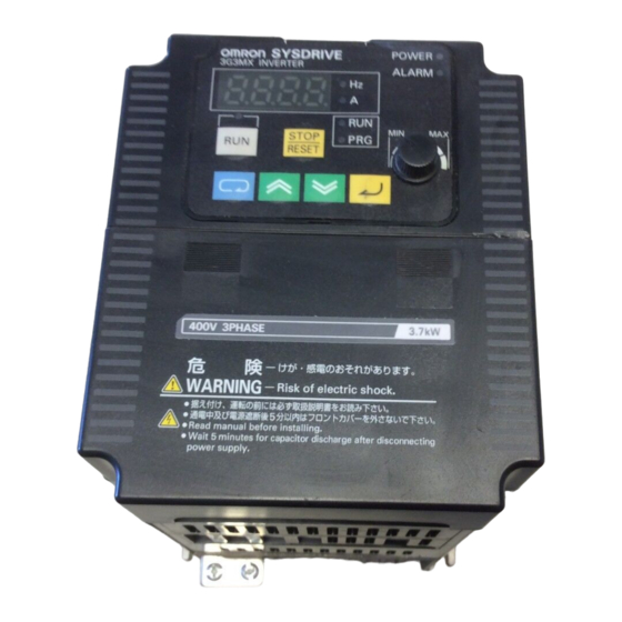
On delivery, be sure to check that the delivered product is the Inverter 3G3MX model that you ordered. Should you find any problems with the product, immediately contact your nearest local sales representative or OMRON sales office. Checking the Nameplate Inverter model... -
Page 13: Revision History
Revision History Revision History A manual revision code appears as a suffix to the catalog number located at the lower left of the front and back covers. I559-E1-01 Cat. No. Revision code Revision code Revision date Changes and revision pages December 2007 First printing... -
Page 14: About This Manual
About This Manual About This Manual This User's Manual is compiled chapter by chapter for user's convenience as follows. Understanding the following configuration ensures more effective use of the product. Overview Chapter 1 Overview Describes features and names of parts. Provides external dimensions, installation dimensions, peripheral device Chapter 2 Design design/selection instructions, and other information necessary for... -
Page 15: Table Of Contents
Contents Introduction....................1 Read and Understand this Manual ............2 Safety Precautions ..................5 Precautions for Safe Use.................7 Precautions for Correct Use ..............8 Checking Before Unpacking ..............10 Revision History..................11 About This Manual...................12 Chapter 1 Overview Functions ....................1-1 Appearance and Names of Parts.............1-3 Chapter 2 Design Installation....................2-1 Removing and Mounting Each Part ............2-5 Wiring.......................2-10... - Page 16 Contents Measurement Method of Output Voltage ..........7-5 Connection Example ................7-6 Dimensional Drawing ................7-8 Options....................7-14 Appendix Appendix-1 Parameter List ................. App-1 Appendix-2 Product Life Curve ..............App-17 Index...
-
Page 17: Chapter 1 Overview
Chapter 1 Overview 1-1 Functions ............1-1 1-2 Appearance and Names of Parts ....1-3... -
Page 18: Functions
1-1 Functions 1Overview 1-1 Functions 3G3MX Inverter Models Rated voltage Enclosure rating Max. applicable motor capacity Model 0.2 kW 3G3MX-A2002 0.4 kW 3G3MX-A2004 0.75 kW 3G3MX-A2007 1.5 Kw 3G3MX-A2015 3-phase 200 V AC 2.2 kW 3G3MX-A2022 3.7 kW 3G3MX-A2037 5.5 kW 3G3MX-A2055 7.5 kW 3G3MX-A2075... - Page 19 1-1 Functions Easy-to-use General-purpose Inverter with Vector Control Functions Advanced Functions High Starting Torque With its vector control, the 3G3MX Series has achieved high starting torque in excess of 200% at 1 Trip Suppression This Inverter features two trip suppression functions: "Overcurrent suppression function" to suppress overcurrent trip during acceleration, and "Overvoltage LAD stop function"...
-
Page 20: Appearance And Names Of Parts
1-2 Appearance and Names of Parts 1-2 Appearance and Names of Parts You can open and close the terminal block cover by hand, without using any tool. When the terminal block cover is removed as illustrated below, you can operate the mode selector and perform wiring to the control circuit terminal block, the main circuit terminal block, and the relay output terminal block. - Page 21 1-2 Appearance and Names of Parts 3G3MX-A2015 to A2037, 3G3MX-A4004 to A4037, 3G3MX-AE007 to AE022 FREQ adjuster Digital Operator Terminal block cover Control circuit Front cover wiring hole Main circuit wiring hole Main housing Bottom cover Ground terminal Control circuit terminal block A Control circuit terminal block B...
- Page 22 1-2 Appearance and Names of Parts 3G3MX-A2055 to A2075, 3G3MX-A4055 to A4075 Digital Operator FREQ adjuster Front cover Terminal block cover Control circuit wiring hole Main circuit wiring hole Bottom cover Main housing Relay output terminal block Control circuit terminal block A Control circuit terminal block B Main circuit terminal block...
- Page 23 1-2 Appearance and Names of Parts Names of Parts (When the Digital Operator is Removed) FREQ adjuster knob Digital Operator Communications Digital Operator connector connection plug POWER LED indicator ALARM LED indicator RUN (RUN LED indicator) Control circuit terminal block A Control circuit terminal block B Relay output terminals...
-
Page 25: Chapter 2 Design
Chapter 2 Design 2-1 Installation ............2-1 2-2 Removing and Mounting Each Part....2-5 2-3 Wiring ..............2-10... -
Page 26: Installation
2-1 Installation 2Design 2-1 Installation WARNING Turn off the power supply and implement wiring correctly. Not doing so may result in a serious injury due to an electric shock. Wiring work must be carried out only by qualified personnel. Not doing so may result in a serious injury due to an electric shock. -
Page 27: Safety Information
2-1 Installation Safety Information Installation and Storage Do not store or use the product in the following places. •Locations subject to direct sunlight. •Locations subject to ambient temperature exceeding the specifications. •Locations subject to relative humidity exceeding the specifications. •Locations subject to condensation due to severe temperature fluctuations. •Locations subject to corrosive or flammable gases. -
Page 28: Precautions For Use
2-1 Installation Precautions for Use Installation •Install the Inverter vertically on the wall or DIN tracks (optional). The material of the wall has to be noninflammable such as a metal plate. Model Position for installing a screw Positions for installing screws Model 3G3MX-A2002 3G3MX-A2015... -
Page 29: Installation Environment
2-1 Installation Installation Environment •Increased ambient temperatures will shorten the life of the Inverter. •Keep the Inverter away from heating elements (such as a braking resistor, DC reactor, etc.). If the Inverter is installed in a control panel, keep the ambient temperature within the range of the specifications, taking dimensions and ventilation into consideration. -
Page 30: Removing And Mounting Each Part
2-2 Removing and Mounting Each Part 2-2 Removing and Mounting Each Part Removing and Mounting the Terminal Block Cover 3G3MX-A2002 to A2037, 3G3MX-A4004 to A4037, 3G3MX-AE002 to AE022 (1) Removing the Terminal Block Cover Press the one side (1) of tab A on the terminal block cover, and use the opposite side of tab A as a supporting point to disconnect tab B on the same side of the pressed tab A. - Page 31 2-2 Removing and Mounting Each Part (2) Mounting the Terminal Cover Push down both sides of A and B simultaneously from the upper side of the terminal cover until it clicks into place. 3G3MX-A2055 to A2075, 3G3MX-A4055 to A4075 (1) Removing the Terminal Block Cover •...
- Page 32 2-2 Removing and Mounting Each Part (2) Mounting the Terminal Block Cover Fit the B tabs on the terminal block cover into the main unit housing, and push down the cover from the upper side until the two A tabs click into place. Removing and Mounting the Digital Operator Removing the Digital Operator Pressing the upper tab on the Digital Operator, pull it up to the Inverter's front (upper direction in the...
- Page 33 2-2 Removing and Mounting Each Part Mounting the Digital Operator Place the bottom of the Digital Operator into the open space in the front cover, and push down the upper side of the Digital Operator. *Supplemental Information Before mounting the Digital Operator, be sure to mount the Digital Operator connection plug. To mount the Digital Operator connection plug, push its tab into the communication connector until it clicks into place.
- Page 34 2-2 Removing and Mounting Each Part Mounting the Control Circuit Terminal Blocks Step (1) Push control circuit terminal block A (Terminals SC, S1 to S6) down securely on the Inverter's front (upper direction in the figure on the previous page). Step (2) Push control circuit terminal block B (Terminals FS, FV, FI, FC, AM, PC, P2, P1) down securely from the Inverter's bottom (right lower direction in the figure on the previous page).
-
Page 35: Wiring
2-3 Wiring 2-3 Wiring Wiring to the Power Supply and Motor Open the terminal block cover and wire the main circuit terminal blocks. 3G3MX-A2002 to A2007, 3G3MX-AE002 to AE004 Frame format of the main circuit terminal block Short-circuit bar P/+2 Upper R/L1 S/L2... -
Page 36: Standard Connection Diagram
2-3 Wiring 3G3MX-A2055 to A2075, 3G3MX-A4055 to A4075 Frame format of the main circuit terminal block R/L1 S/L2 T/L3 U/T1 V/T2 W/T3 Upper P/+2 Lower Main circuit Short-circuit bar terminal block Standard Connection Diagram DC reactor Braking resistor (optional) (optional) P/+2 N/–... - Page 37 2-3 Wiring Connecting to the Power Supply and Motor R/L1 S/L2 T/L3 U/ T1 V T2 W/ T3 (L1) (L2) (N/L3) Inverter Motor Power supply * Terminal symbols for 3G3MX-AE are indicated in parentheses ( ). •Do not connect the power supply other than to R/L1, S/L2, or T/L3. •Do not remove the short-circuit bar between P/+2 and +1, except when a DC reactor is connected.
- Page 38 2-3 Wiring Wiring the Control Circuit Terminals and Relay Output Terminals Relay Control circuit terminal block A Relay output terminal block Control circuit terminal block B Relay output Wiring Example of the Control Circuit Terminal Block (Sink Logic) At sink logic (NPN): External power supply input At source logic (PNP): Power supply output...
- Page 39 2-3 Wiring Perform insulating treatment. Ground connection is not required. Connect to the ground terminal of the Inverter. Note 3: Separate the wiring from the power cable of the main circuit and from the wiring on the relay control circuit. (More than 10 cm apart.) Selecting the Sequence Input Method (Sink/Source Logic) Inverter's internal circuitry When external power supply is used...
-
Page 40: Connecting The Main Circuit Terminals
2-3 Wiring Wiring the Main Circuit Terminals Connecting the Main Circuit Terminals Wiring Applicable device Motor output Fuse size Applicable Inverter model Earth leakage breaker (kW) Power cable (class J) (ELB) Rated 600 V 3G3MX-A2002 1.25 mm (5 A) 10 A 3G3MX-A2004 10 A 1.25 mm... - Page 41 2-3 Wiring Choose the sensitivity current of the earth leakage breaker (ELB), depending on the total distance (L) between the Inverter and the power supply, and the Inverter and the motor. Sensitivity Guide of leakage current: If a CV wire is used and routed through a metal pipe, current (mA) the leakage current is 30 mA/km.
-
Page 42: Main Circuit Connection Diagram
2-3 Wiring Screw Tightening Torque Control Circuit Terminal Block Screw Tightening torque SC S6 S5 S4 S3 S2 S1 PSC 0.2 N•m (max. 0.25 N•m) FS FV FI FC AM PC P2 P1 M2.5 0.5 N•m (max. 0.6 N•m) M3.5 0.8 N•m (max. - Page 43 2-3 Wiring Wiring the Main Circuit Terminals (Input Side) Installing a Molded-case Circuit Breaker (MCCB) •Always connect the Inverter and power supply via a molded-case circuit breaker (MCCB) to protect the Inverter from damage that may result from short-circuiting. •Always connect the power input terminals (R/L1, S/L2, and T/L3) and power supply via an MCCB, according to the Inverter capacity.
- Page 44 2-3 Wiring Installing an AC Reactor •If the Inverter is connected to a large-capacity power transformer (660 kVA or more) or the phase advance capacitor is in use, a large peak current may flow through the input power circuit, causing the converter unit to break down.
- Page 45 2-3 Wiring Installing a Noise Filter on the Input Side •The Inverter's output uses high-speed switching, so noise may be transmitted from the Inverter to the power line, affecting peripheral devices. •It is recommended that a noise filter be installed on the input side to minimize noise transmission. (Installing a noise filter on the input side can also reduce the noise from the power line to the Inverter.) <Recommended Input Noise Filters for the Inverter>...
- Page 46 2-3 Wiring Wiring the Main Circuit Terminals (Output Side) Connect the Terminal Block to the Load •Connect motor output terminals U/T1, V/T2, and W/T3 to motor lead wires U, V, and W. •Check that the motor rotates forward with the forward command. Switch over any two of the output terminals (U/T1, V/T2, W/T3) and reconnect if the motor rotates in reverse to the forward command.
- Page 47 2-3 Wiring Countermeasures Against Induction Noise To reduce induction noise from the output side, the following method is also effective. •Run the cables collectively through the mounted metal pipe. Keeping the metal pipe at least 30 cm away from the signal line reduces induction noise. Molded case circuit-breaker (MCCB)
- Page 48 2-3 Wiring Specifications of Control Circuit Terminals Terminal Terminal name and function Default setting Specifications symbol 24 V DC ±10% External power supply terminal for input 30 mA max. signal (input) ...At sink logic Internal power supply output terminal for 24 V ±10% input signal (output) ...At source logic...
- Page 49 2-3 Wiring *1. Below are the contact specifications of the relay outputs. Output terminal Resistance load Inductive load 250 V AC, 2 A 250 V AC, 0.2 A Max. contact capacity 30 V DC, 3 A 30 V DC, 0.6 A MA-MC 100 V AC, 10 mA Min.
- Page 50 2-3 Wiring <Frequency Reference/RUN Command Source Selector> Switches the source for frequency reference and RUN command of the Inverter. Symbol Name Status Description Control terminal block (terminals): The set values in A001 and A002 are disabled. Frequency reference: Analog external input (FV, FI) RUN command : Operation using the FW or RV terminal 00(FW) or 01 (RV) must be allocated to the...
- Page 51 2-3 Wiring Functions of the Control Circuit Terminals Terminal Terminal Terminal name Function and connecting method Wire size function Symbol Select functions and allocate them to terminals S1 to S6. (The figure below illustrates the wiring of the sink logic.) Contact input Multi-function (for switching...
- Page 52 2-3 Wiring *1. By factory default, multi-function output terminals, [P1] and [P2] are set to NO contact. To switch to NC contact, change the C031 and C032 settings. In addition, these terminals are reset to NO contact when initialized. *2.The factory default setting (C036) of the relay output terminals (MA, MB-MC) is set to NC contact. In addition, these terminals are reset to NC contact when initialized.
- Page 53 2-3 Wiring Mode Selector List Symbol Name Description Available to switch the input logic (source or sink) in the multi-function input terminal circuit. Input logic SR/SK Source logic selector Sink logic [factory default] Select the mode according to the option connected to the communications connector. RS-485 com- munication/ 485/OPE...
-
Page 54: Conforming To Ec Directives
Concept of Conformity EMC Directive OMRON products are the electrical devices incorporated and used in various machines or manufacturing equipment. For this reason, we make efforts to conform our products to their related EMC standards so that the machines or equipment which have incorporated our products should easily conform to the EMC standards. - Page 55 Chapter 3 Operation 3-1 Test Run Procedure ......... 3-2 3-2 Test Run Operation.......... 3-3 3-3 Part Names and Descriptions of the Digital Operator ............3-8 3-4 Operation Procedure (Example: Factory Default) ................3-10 3-5 Keys..............3-16 3-6 Parameter Transition ........3-17 3-7 Parameter List ..........
- Page 56 3Operation WARNING Do not put on or take off the Digital Operator•control circuit terminal block•terminal block cover while the input power is being supplied. Doing so may result in a serious injury due to an electric shock. Do not remove the terminal block cover during the power supply and 5 minutes after the power shutoff.
-
Page 57: Test Run Procedure
3-1 Test Run Procedure 3-1 Test Run Procedure Item Description Reference page Installation and Mounting Install the Inverter according to the installation conditions. •Make sure that the installation conditions are met. Wiring and Connection Connect to the power supply and peripheral devices. 2-10 •Select peripheral devices that meet the specifications, and wire correctly. -
Page 58: Test Run Operation
3-2 Test Run Operation 3-2 Test Run Operation Power On Checkpoints Before Turning On the Power •Make sure that an appropriate power supply voltage is supplied and that the power input terminals (R/L1, S/L2, and T/L3) are wired correctly. 3G3MX-A2 : 3-phase 200 to 240 V AC 3G3MX- AE : 1/3-phase 200 to 240 V AC (Connect to L1 and N/L3 for 1 phase) 3G3MX-A4 : 3-phase 380 to 480 V AC •Make sure that the motor output terminals (U/T1, V/T2, and W/T3) are connected to the motor... -
Page 59: Parameter Initialization
3-2 Test Run Operation Parameter Initialization •Initialize the parameters using the following procedure. •To initialize the parameters, set parameter b084 to "02". Key sequence Display example Description k0.0 Power On Press the Mode key once, and then press the Decrement key three bk-k-k- times to display "b---". - Page 60 3-2 Test Run Operation Setting the Motor Capacity Selection (H003), Motor Pole Number Selection (H004) and Motor Voltage Selection (H007) Interrupt Parameter Unit of Default Name Description Setting range during Setting setting 200-V class 0.2/0.4/0.75/1.5/ Sets the capacity of the Motor capacity 2.2/3.7/5.5/7.5 Varies with...
-
Page 61: Actual Load Operation
3-2 Test Run Operation No-load Operation •Start the no-load motor (i.e., not connected to the mechanical system) using the Digital Operator. * Before operating the Digital Operator, check that the FREQ adjuster is set to "MIN." * Make sure that the LED indicator above the FREQ adjuster and the RUN command LED indicator are lit. - Page 62 3-2 Test Run Operation Checking the Operating Status •After making sure that the operating direction is correct and that the Inverter is operating smoothly at a slow speed, increase the frequency reference. •By changing the frequency reference or the rotation direction, make sure that there is no vibration or abnormal sound from the motor.
-
Page 63: Part Names And Descriptions Of The Digital Operator
3-3 Part Names and Descriptions of the Digital Operator 3-3 Part Names and Descriptions of the Digital Operator MX INVERTER Data display RUN command LED indicator Operation keys FREQ adjuster Name Description POWER LED indicator Lit when the power is supplied to the control circuit. ALARM LED indicator Lit when an Inverter error occurs. - Page 64 3-3 Part Names and Descriptions of the Digital Operator Name Description Enters the set value. Enter key (To change the set value, be sure to press the Enter key.) Changes the mode. Increment key Also, increases the set value of each function. Changes the mode.
-
Page 65: Operation Procedure (Example: Factory Default)
3-4 Operation Procedure (Example: Factory Default) 3-4 Operation Procedure (Example: Factory Default) Displaying the Monitor Mode, Basic Function Mode, and Extended Function Mode Power On 1. The data of the set monitor is displayed. (Default is "0.0") Press 2. The code of the monitor mode is displayed (as "d001"). •Press the Mode key once to return from the code display of the monitor mode to the monitor Ddk0k0k1... - Page 66 3-4 Operation Procedure (Example: Factory Default) 3. The code of the basic function mode is displayed (as "F001"). Dfk0k0k1 Press Press (4 times) (4 times) 4. The extended function mode is displayed (as "A---"). •Extended function mode Displays in order of A ⇔ b ⇔ C ⇔ H. ak-k-k- Press Press...
- Page 67 3-4 Operation Procedure (Example: Factory Default) Setting Functions •Switch the method of the RUN command. (Digital Operator → Control terminal block) •To switch the method of the RUN command from the Digital Operator (factory default) to the control terminal block, you need to change the frequency reference selection (A001) from the Digital Operator (02) to the terminal (01).
- Page 68 3-4 Operation Procedure (Example: Factory Default) (Change the A002 setting.) •Change the RUN command source to the control terminal "01". Press 4. The code of the monitor mode is displayed (as "A002"). •Press the Enter key to fix the changed setting data.
- Page 69 3-4 Operation Procedure (Example: Factory Default) 2. Change the function code. •You can change the 4th digit when "d" blinks. dk0k0k1 Press (2 times) ("A001" is displayed.) •"A" blinks. •Press the Enter key to fix the blinking digit. ak0k0k1 Press ("A"...
- Page 70 3-4 Operation Procedure (Example: Factory Default) ("A021" is displayed.) •"2" of the 2nd digit blinks. ak0k2k1 Press 5. Change the 1st digit of the function code. •"1" of the 1st digit blinks. •Press the Mode key to start "0" of the 2nd digit ak0k2k1 blinking again.
-
Page 71: Keys
3-5 Keys 3-5 Keys Name Description Switches between the command setting and the data setting, and between the extended function mode and the basic function mode. With this key, you can always change the display as follows: [Supplemental Information] To jump to "d001" from any function mode, hold down the Mode key for 3 seconds. -
Page 72: Parameter Transition
3-6 Parameter Transition 3-6 Parameter Transition dk0k0k1 Press the key. dk0k8k3 fk0k0k1 fk0k0k4 ak0k0k1 ak-k-k- ak0k0k1 0k0k0k0 0k0k0k1 9k9k9k9 bk-k-k- ak0k0k2 0k0k0k0 ck-k-k- 0k0k0k1 9k9k9k9 ak0k0k3 hk-k-k- *1. Data is not stored by pressing the Mode key. *2. Press the Enter key to store the data. *3. - Page 73 3-6 Parameter Transition * To display a specific monitor when the power is turned on, press the Enter key with that monitor displayed. If a parameter for an extended function code is stored after pressing the Enter key, however, that code (A---, b---, C---, d---, or H---) appears at the next power-on.
-
Page 74: Parameter List
3-7 Parameter List 3-7 Parameter List Monitor Mode (d ) / Basic Function Mode (F Changes Parameter Monitor or data range Default Function name during Unit Page (Digital Operator) setting operation Output frequency d001 0.0 to 400.0 monitor ... - Page 75 3-7 Parameter List Changes Parameter Monitor or data range Default Function name during Unit Page (Digital Operator) setting operation 0.01 to 99.99 F002 Acceleration time 1 100.0 to 999.9 10.0 1000. to 3000. 0.01 to 99.99 2nd acceleration F202 100.0 to 999.9 10.0 time 1 1000.
-
Page 76: Extended Function Mode
3-7 Parameter List Extended Function Mode Changes Parameter Monitor or data range Default Function name during Unit Page (Digital Operator) setting operation Frequency 00: Digital Operator (FREQ adjuster) A001 reference 4-66 01: Terminal selection 02: Digital Operator (F001) *2nd frequency 03: Modbus communication ... - Page 77 3-7 Parameter List Changes Parameter Monitor or data range Default Function name during Unit Page (Digital Operator) setting operation Multi-step speed A020 0.0/Starting frequency to Max. frequency reference 0 4-42 *2nd multi-step A220 0.0/Starting frequency to 2nd max. frequency speed reference 0 Multi-step speed A021 reference 1...
- Page 78 3-7 Parameter List Changes Parameter Monitor or data range Default Function name during Unit Page (Digital Operator) setting operation Manual torque A042 boost voltage 0.0 to 20.0 4-11 *2nd manual A242 torque boost voltage Manual torque A043 boost frequency 0.0 to 50.0 4-11 *2nd manual A243...
- Page 79 3-7 Parameter List Changes Parameter Monitor or data range Default Function name during Unit Page (Digital Operator) setting operation DC injection 00: Disabled A051 4-14 braking selection 01: Enabled DC injection A052 0.0 to 60.0 4-14 braking frequency DC injection A053 0.0 to 5.0 4-14...
- Page 80 3-7 Parameter List Changes Parameter Monitor or data range Default Function name during Unit Page (Digital Operator) setting operation 00: Disabled A071 PID selection 4-18 01: Enabled A072 PID P gain 0.2 to 5.0 4-18 A073 PID I gain 0.0 to 150.0 4-18 A074...
- Page 81 3-7 Parameter List Changes Parameter Monitor or data range Default Function name during Unit Page (Digital Operator) setting operation Acceleration A092 15.00 0.01 to 99.99 time 2 100.0 to 999.9 4-22 *2nd acceleration 1000. to 3000. A292 15.00 time 2 Deceleration A093 15.00...
- Page 82 3-7 Parameter List Changes Parameter Monitor or data range Default Function name during Unit Page (Digital Operator) setting operation Operation 00: Digital Operator (F001) A141 frequency input A 4-23 01: Digital Operator (FREQ adjuster) setting 02: Input FV Operation 03: Input FI ...
- Page 83 3-7 Parameter List Changes Parameter Monitor or data range Default Function name during Unit Page (Digital Operator) setting operation Electronic thermal Rated b012 level current 0.2 × Rated current to 1.2 × Rated current 4-27 *2nd electronic Rated b212 thermal level current Electronic thermal b013...
- Page 84 3-7 Parameter List Changes Parameter Monitor or data range Default Function name during Unit Page (Digital Operator) setting operation 00: Clears the trip monitor Initialization b084 01: Initializes data 4-32 selection 02: Clears the trip monitor and initializes data Initialization ...
- Page 85 3-7 Parameter List Changes Parameter Monitor or data range Default Function name during Unit Page (Digital Operator) setting operation 00: FW (forward) Multi-function C001 01: RV (reverse) input 1 selection 02: CF1 (multi-step speed binary 1) *2nd multi-function 03: CF2 (multi-step speed binary 2) C201 input 1 selection 04: CF3 (multi-step speed binary 3)
- Page 86 3-7 Parameter List Changes Parameter Monitor or data range Default Function name during Unit Page (Digital Operator) setting operation 00: RUN (signal during RUN) Multi-function 01: FA1 (constant speed arrival signal) C021 output terminal P1 02: FA2 (over set frequency arrival signal) selection 03: OL (overload warning) Multi-function...
- Page 87 3-7 Parameter List Changes Parameter Monitor or data range Default Function name during Unit Page (Digital Operator) setting operation Communication 04: 4800 bps speed selection C071 05: 9600 bps 4-66 (Baud rate 06: 19200 bps selection) Communication C072 station No.
- Page 88 3-7 Parameter List Changes Parameter Monitor or data range Default Function name during Unit Page (Digital Operator) setting operation Use "00". C091 Not used * Do not change. 00: Do not store the frequency data C101 UP/DWN selection 4-50 01: Store the frequency data...
- Page 89 3-7 Parameter List Changes Parameter Monitor or data range Default Function name during Unit Page (Digital Operator) setting operation Motor capacity Factory H003 selection default 200-V class 0.2/0.4/0.75/1.5/2.2/3.7/5.5/7.5 4-63 400-V class 0.4/0.75/1.5/2.2/3.7/5.5/7.5 *2nd motor Factory H203 capacity selection default Motor pole number H004 selection Pole...
-
Page 91: Chapter 4 Functions
Chapter 4 Functions 4-1 Monitor Mode............ 4-1 4-2 Function Mode..........4-5... -
Page 92: Monitor Mode
4-1 Monitor Mode 4Functions 4-1 Monitor Mode Output Frequency Monitor [d001] Displays the output frequency of the Inverter. The monitor LED indicator "Hz" lights up while d001 is displayed. (Display) 0.0 to 400.0: Displays in increments of 0.1 Hz. Output Current Monitor [d002] Displays the output current value of the Inverter. - Page 93 4-1 Monitor Mode Multi-function Input Monitor [d005] Displays the input status of the multi-function input terminals. C011 to C016 (contact selection) are excluded. (Example) Multi-function input terminal S2,S1:ON Multi-function input terminal S6,S5,S4,S3:OFF Display (OFF) (OFF)(OFF) (OFF)(ON) (ON) Multi-function input monitor Multi-function Output Monitor [d006] Displays the output status of the multi-function output terminals and relay output terminals.
- Page 94 4-1 Monitor Mode Output Voltage Monitor [d013] Displays the output voltage value (Vac) of the Inverter. The monitor LED indicator "V" lights up. (Display) 0. to 600.: Displays in increments of 1 V. Total RUN Time [d016] Displays the Inverter RUN time. (Display) 0.
- Page 95 4-1 Monitor Mode (Trip Monitor Display Sequence) (1) Trip factor (2) Trip frequency (3) Trip current (4) Trip P-N (5) Total RUN (6) Power ON time (*2) voltage time dk0k8k1 ekLk0k7 6k0.0 3k9k8. 1k5. 1k8. *2. Displays if there has been no trip. _k_k_k_...
-
Page 96: Function Mode
4-2 Function Mode 4-2 Function Mode <Group F: Basic Function Parameter> Output Frequency Setting/Monitor •Set the Inverter output frequency. •With the frequency reference set to the Digital Operator ([A001] = 02), you can set the output frequency in F001. For other methods, refer to the [A001] section in "Frequency Reference Selection"... - Page 97 4-2 Function Mode •The set time here indicates the acceleration/deceleration time from 0 Hz to the maximum frequency. Output frequency Maximum frequency Output frequency set value A004/A204 Actual Actual acceleration deceleration time time F003/F203 F002/F202 Even if a short acceleration/deceleration time is set, the actual time cannot be shorter than the min- imum acceleration/deceleration time that is determined by the mechanical inertia moment and the motor torque.
-
Page 98: Frequency Reference Selection
4-2 Function Mode <Group A: Standard Function Parameter> Frequency Reference Selection Select the method for using the frequency reference. Parameter No. Function name Data Default setting Unit Frequency reference 00: Digital Operator (FREQ adjuster) A001 selection 01: Terminal 02: Digital Operator (F001) *2nd frequency 03: ModBus communication A201... -
Page 99: Run Command Selection
4-2 Function Mode Data Frequency reference source FREQ adjuster Voltage or current directive from the terminal F001 value set via the Digital Operator ModBus communication Result of the frequency operation function RUN Command Selection Select the method for using the RUN/STOP command. Parameter No. -
Page 100: Maximum Frequency
4-2 Function Mode Output voltage Motor voltage selection (A082) Output frequency (Hz) Base frequency (A003/A203) •If you apply a base frequency of over 60 Hz, a special motor is required. This may require the Inverter to increase its capacity to accommodate a different applicable motor. •Select the motor voltage according to the motor specifications. - Page 101 4-2 Function Mode Analog Input (FV, FI) The Inverter has two types of analog input terminals. FV-FC terminal: 0 to 10 V (voltage input) FI-FC terminal: 4 to 20 mA (current input) Simultaneous inputs are not acceptable. Do not connect the signal lines for inputs FV and FI simultaneously.
- Page 102 4-2 Function Mode Parameter No. Function name Data Default setting Unit Related functions A005, A016, AT input •To input voltage ranging from 0 to 5 V on the FV-FC terminal, set A014 to 50%. (Example 1) A015/A105/A155: 00 (Example 2) A015/A105/A155: 01 Maximum Maximum frequency...
- Page 103 4-2 Function Mode Parameter No. Function name Data Default setting Unit 00: Constant torque characteristics A044 V/f characteristics selection (VC) 01: Special reduced torque * 2nd V/f characteristics characteristics (Special VP) A244 selection 02: Intelligent sensorless vector control (iSLV) A045 Output voltage gain 20.
-
Page 104: Torque Boost
4-2 Function Mode Torque Boost •Compensates for the voltage drop caused by the motor primary resistance or by wiring and suppresses torque reduction at a low speed range. Manual Torque Boost [A042/A242, A043/A243] •Adds the voltage characteristics set in A042/A242 and A043/A243 to the V/f characteristics, and outputs the resulting voltage. -
Page 105: Output Voltage Gain
4-2 Function Mode Output Voltage Gain •Changes the Inverter output voltage in percentages, with the voltage selected in the AVR voltage selection (A082) as 100%. •The Inverter cannot output voltage beyond that of the incoming voltage. Motor voltage selection (100%) (A082) A045 Base frequency Max. - Page 106 4-2 Function Mode • External DC Injection Braking (A051 = 00) •Allocate 07 (DB) to the desired multi-function input. •DC injection braking can be applied by turning on/off the DB terminal, regardless of the DC injection braking selection (A051). •Adjust the DC injection braking power with A054. •If the DC injection braking delay time (A053) is set, the Inverter output will be shut off during the specified time period and the motor goes into free-run status.
- Page 107 4-2 Function Mode (a) Edge operation (A056: 00) (b) Level operation (A056: 01) (Example 4-a) Output frequency A055 A055 • Internal DC Injection Braking (A051 = 01) •Performs DC injection braking to stop the motor without any terminal operation. To use this function, set the DC injection braking selection (A051) to 01.
-
Page 108: Frequency Limit
4-2 Function Mode (Example 6-a) (Example 6-b) Output Output frequency frequency A055 A055 A052 A052 Frequency Limit This function limits the Inverter output frequency. Parameter No. Function name Data Default setting Unit 0.0/Frequency lower limit [A062] to A061 Frequency upper limit Max. -
Page 109: Frequency Jump Function
4-2 Function Mode Frequency Jump Function This function helps avoid resonant points of loaded machines. Parameter No. Function name Data Default setting Unit A063 Jump frequency 1 A065 Jump frequency 2 0.0 to 400.0 A067 Jump frequency 3 A064 Jump frequency width 1 A066 Jump frequency width 2 0.0 to 10.0... - Page 110 4-2 Function Mode Parameter No. Function name Data Default setting Unit PID deviation C044 0. to 100. excessive level C052 PID FB upper limit 0.0 to 100.0 C053 PID FB lower limit Related functions d004, A001, A005, C001 to C006, C021 to C022, C026 •To use this function, set A071 to 01.
-
Page 111: Pid Feedback Value Monitor
4-2 Function Mode D Operation •Operation where the control volume is proportional to the variation ratio of the target value Target value Large Large A074 A074 Small Control volume Small •PI operation is the combination of the above P and I operations; PD is P and D operations; PID is P, I and D operations. -
Page 112: Avr Function
4-2 Function Mode PID Comparison Function •This function outputs a signal when detecting that the PID feedback value exceeds the set range. •Allocate 07 (FBV) to any of multi-function output terminals P1 and P2 (C021 and C022) or relay output terminals MA and MB (C026). •Set the upper limit in C052, and the lower limit in C053. - Page 113 4-2 Function Mode 2-step Acceleration/Deceleration Function (2CH) By setting this function, you can change the acceleration/deceleration time during acceleration/de- celeration. Parameter No. Function name Data Default setting Unit 0.01 to 99.99 A092 Acceleration time 2 15.0 100.0 to 999.9 A292 * 2nd acceleration time 2 15.0 1000.
- Page 114 4-2 Function Mode Acceleration/Deceleration Pattern This function is used when smooth acceleration/deceleration is needed. Parameter No. Function name Data Default setting Unit 00: Line A097 Acceleration pattern selection 01: S-shape curve 00: Line A098 Deceleration pattern selection 01: S-shape curve •Acceleration/deceleration pattern can be set according to each system.
-
Page 115: Frequency Addition Function
4-2 Function Mode A141 Digital Operator A143 FREQ adjuster Input FV Input A Input FI Result of ModBus communication calculation – Output frequency × Digital Operator FREQ adjuster Input B Input FV Input FI A142 ModBus communication Frequency Addition Function This function adds or subtracts the constant frequency set in A145 to/from the output frequency. - Page 116 4-2 Function Mode <Group B: Detailed Function Parameters> Momentary Power Interruption/Trip Retry (Restart) This function allows you to determine the operation performed when a trip occurs due to momentary power interruption, undervoltage, overcurrent, or overvoltage. Set the retry condition according to your system. Parameter No.
- Page 117 4-2 Function Mode •Below is the timing chart where the retry function (b001: 02) is selected. (Example 1) Duration of momentary power interruption (Example 2) Duration of momentary power interruption < Allowable duration of momentary power > Allowable duration of momentary power interruption (b002) interruption (b002) Power supply...
-
Page 118: Electronic Thermal Function
4-2 Function Mode Electronic Thermal Function •This function electronically protects the motor from overheating. Parameter No. Function name Data Default setting Unit b012 Electronic thermal level Rated current 0.2 × Rated current to 1.2 × Rated * 2nd electronic thermal current b212 Rated current... - Page 119 4-2 Function Mode Reduced Torque Characteristics 1 •Multiplied by the time limit characteristics set in b012/212 for each frequency. (Example) 3G3MX-A2007 (Rated current: 5.0 A), b012 = 5.00 (A), Output frequency = 20 Hz Trip time (s) Torque X1.0 X0.8 X0.6 Inverter output Motor current (A)
-
Page 120: Overload Limit
4-2 Function Mode Overload Limit/Overload Warning This function helps prevent an overcurrent trip due to rapid load fluctuation in acceleration or constant speed operation. Parameter No. Function name Data Default setting Unit 00: Disabled b021 Overload limit selection 01: Enabled in acceleration/constant *2nd overload limit speed operation ... - Page 121 4-2 Function Mode Overload limit level b022 Deceleration set by the overload limit parameter Output current Maximum frequency Target frequency A004/A204 F001 Inverter output frequency b023 Overload Warning •If the load is too large, this function outputs an overload warning signal, allowing you to readjust the overload level to prevent a trip.
-
Page 122: Starting Frequency
4-2 Function Mode AM Adjustment You can adjust the analog voltage (0 to 10 V DC) from the AM terminal on the control terminal block. Parameter No. Function name Data Default setting Unit Default b080 AM adjustment 0. to 255. adjustment value 00: Output frequency ... -
Page 123: Carrier Frequency
4-2 Function Mode Carrier Frequency You can change the PWM waveform carrier frequency output from the Inverter with b083. Parameter No. Function name Data Default setting Unit b083 Carrier frequency 2.0 to 14.0 •With the carrier frequency set high, you can reduce metallic noise form the motor. However, this may increase noise or leakage current from the Inverter. - Page 124 4-2 Function Mode Initialization Method After setting the parameter, use the following method to initialize. (1) Press the STOP/RESET key with the Mode and Increment/Decrement keys pressed simultaneously. Release the STOP/RESET key when the display blinks. Release the Mode and Increment/Decrement keys. (2) Initializing (3) Initialization completes with "d001"...
-
Page 125: Stabilization Parameter
4-2 Function Mode Stabilization Parameter •This function adjusts to reduce motor hunting. •In case of motor hunting, check whether the motor capacity selection (H003/H203) and motor pole number selection (H004/H204) match your motor. If they do not, match them. •For adjustment, raise the stabilization parameter (H006) by degrees. If this increases motor hunting, lower it by degrees. -
Page 126: Stop Key Selection
4-2 Function Mode Frequency Conversion Coefficient This function displays a conversion value obtained by multiplying the Inverter output frequency by the coefficient set in [b086]. This helps display the actual physical value on the monitor. Function code Item Data Default setting Unit Frequency conversion ... -
Page 127: Cooling Fan Control
4-2 Function Mode •Note that an overcurrent trip may occur if the mechanical brake forces the motor to stop during Inverter output. •Allocate 11 (FRS) to the desired multi-function input. •Performs a free-run stop (FRS) while the FRS terminal is turned on. When the FRS terminal is turned off, the motor restarts after retry wait time b003 elapses. -
Page 128: Regenerative Braking Function
4-2 Function Mode Regenerative Braking Function •With the built-in regenerative braking circuit, this function allows an external braking resistor to consume the motor's regeneration energy as heat. This function is useful for a system in which the motor works as a generator when it is rapidly decelerated. - Page 129 4-2 Function Mode Overvoltage LAD Stop Function •This function helps avoid an overvoltage trip of the Inverter due to regenerative energy from the motor during deceleration. Parameter No. Function name Data Default setting Unit Overvoltage LAD stop 00: Disabled b130 function 01: Enabled...
-
Page 130: Overcurrent Suppression Function
4-2 Function Mode Overcurrent Suppression Function •This function suppresses overcurrent caused by a steep current rise in rapid acceleration. •Select to enable or disable the overcurrent suppression function in b140. •This function does not operate during deceleration. Parameter No. Function name Data Default setting Unit... -
Page 131: Rdy (Ready) Function
4-2 Function Mode RDY (Ready) Function This function prepares for Inverter output to rotate the motor immediately after a RUN command is input. Parameter No. Function name Data Default setting Unit 00: Disabled b151 Ready function selection 01: Enabled •When this function is enabled, the RUN (during RUN) LED indicator is always lit, since the Inverter is in output status even though the motor stops. - Page 132 4-2 Function Mode •The same two functions cannot be allocated to the multi-function inputs. If you attempt to allocate the same two functions to the terminals by mistake, the terminal where you allocated the function last takes precedence. The previous data is set to "255", and the terminal function is disabled. Parameter No.
- Page 133 4-2 Function Mode •In the following multi-function input settings, if you allocate a function to one code (C001 to C006), the same function will be allocated to the other code (C201 to C206) automatically. 08: 2nd control, 11: Free run, 12: External trip, 18: Reset, 19: Thermistor input, 23: PID enabled/disabled, 53: Special 2nd function •"08: 2nd control"...
- Page 134 4-2 Function Mode •You can also select a multi-step speed by turning on/off the multi-step speed terminals (CF1 to CF4) and set the multi-step speed frequency with F001. Multi-step speed terminals Multi-step speed 11th 10th Frequency reference 12th from the Digital Operator 13th or the external analog 14th...
- Page 135 4-2 Function Mode Jogging Frequency (When A039 = 01) Output frequency A038 •The Inverter may easily lead to a trip if the jogging frequency is set to high. Adjust A038 so that the Inverter does not trip. Jogging Stop Selection •The deceleration time depends on the currently selected deceleration time in F003, F203, A093, or A293.
- Page 136 4-2 Function Mode U/T1 Motor V/T2 W/T3 Motor Inverter /SP-SET •To display and set each parameter for the 2nd control (200s of function codes), allocate SET and SP-SET. •Parameters changeable during operation are as follows: Selection Parameter No. Function name SP-SET F002/F202 Acceleration time 1...
-
Page 137: External Trip
4-2 Function Mode Selection Parameter No. Function name SP-SET b022/b222 Overload limit level b023/b223 Overload limit parameter b028/b228 Overload limit source selection C001/C201 Multi-function input 1 selection C002/C202 Multi-function input 2 selection C003/C203 Multi-function input 3 selection C004/C204 Multi-function input 4 selection C005/C205 Multi-function input 5 selection C006/C206... -
Page 138: Power Recovery Restart Prevention Function
4-2 Function Mode Power Recovery Restart Prevention Function For safety reasons, this function causes a USP trip (E13) while the RUN command (FW/RV) from the control terminal (terminal) is turned on, in either of the following conditions: • When the power is turned on •... -
Page 139: Thermistor Trip Function
4-2 Function Mode Reset This function resets an Inverter trip. Data Symbol Function name Status Description Shuts off the power if the Inverter is running. Cleared at trip. Reset (The same process as when the power is turned on) Same as above. Available input terminals C001, C002, C003, C004, C005, C006 Required settings... - Page 140 4-2 Function Mode 3-wire Input Function •This function is effective in using auto recovery contacts such as a press button switch for operation and stop. Data Symbol Function name Status Description Starts with auto recovery contacts. 3-wire start Irrelevant to the motor operation. Stops with auto recovery contacts.
-
Page 141: Up/Down Function
4-2 Function Mode UP/DOWN Function This function changes the Inverter output frequency using the multi-function input. Data Symbol Function name Status Description Increases the current speed during the signal UP/DWN function input period. accelerated Keeps the current speed. Decreases the current speed during the signal UP/DWN function input period. - Page 142 4-2 Function Mode RUN commands (FW and RV) Acceleration/Deceleration does not function if the UP and DWN terminals are turned on simultaneously. Output frequency Forced Operator Function This function forcibly switches to operation via the Digital Operator by turning on/off the multi- function terminal if the frequency reference/RUN command sources are not set to the Digital Operator.
- Page 143 4-2 Function Mode Frequency reference source A001 FREQ adjuster Terminal block Output frequency setting Σ F001 set value ModBus communication +/– Logic operation output Frequency addition direction setting A146 Frequency addition A145 [ADD] Multi-function input Forced Terminal Block Function This function forcibly switches to operation via the terminal block by turning on/off the multi-function terminal when the frequency reference/RUN command sources are not set to the terminal block.
- Page 144 4-2 Function Mode Multi-function Output Selection Parameter No. Function name Data Default setting Unit 00: RUN (signal during RUN) Multi-function output 01: FA1 (constant speed arrival signal) C021 terminal P1 selection 02: FA2 (over set frequency arrival signal) 03: OL (overload warning) Multi-function output ...
- Page 145 4-2 Function Mode •This signal is also output during DC injection braking. Below is the time chart. Output frequency Frequency Arrival Signal •This function outputs a signal when the output frequency has reached the set value. For elevating machines, use this signal for applying the brake. Data Symbol Function name...
- Page 146 4-2 Function Mode Output Over Set Frequency (02: FA2) •Outputs a signal when the output frequency has exceeded the arrival frequencies during acceleration/deceleration set in [C042, C043 (FA2)]. C042 C043 f on :1% of max. frequency f on f off f off :2% of max.
-
Page 147: Alarm Output
4-2 Function Mode Excessive PID Deviation Output This function outputs a signal when the deviation has exceeded the set value during the use of the PID function. Data Symbol Function name Status Description The PID deviation has exceeded the C044 set value. - Page 148 4-2 Function Mode Data Symbol Function name Status Description The Inverter is in trip status. Alarm output The Inverter is normal. Available input terminals P1-PC, P2-PC, MA-MC (or MB-MC) Required settings C021, C026 External Analog Input Disconnection Detection •Outputs a signal if an error is detected in the external analog inputs (FV, FI). Data Symbol Function name...
- Page 149 4-2 Function Mode PID FB Status Output When the PID function is used, this function outputs a signal according to the FB value, as illustrated below. This is effective as a RUN command in operating multiple pumps. Data Symbol Function name Status Description See the figure below.
-
Page 150: Logic Output Function
4-2 Function Mode Logic Operation Output This function outputs a logic operation result of the set two status. Data Symbol Function name Status Description Logic operation output See the figure below. Available input terminals P1-PC, P2-PC, MA-MC (or MB-MC) Required settings C021, C026, C141, C142, C143 Multi-function output item C141... - Page 151 4-2 Function Mode Multi-function Output Terminal ON Delay/OFF Delay This function allows you to set ON/OFF delay times respectively from 0.1 to 100 seconds at the signal output of the multi-function output terminals (P1 and relay). The following figure shows the output status.
- Page 152 4-2 Function Mode Specifications of Multi-function Output Terminals P1, P2 •Below are the specifications of multi-function output terminals P1, P2. Inverter's internal circuitry Power C031 to C032 set values Output status Electrical specifications supply Between each terminal and PC Voltage drop 4 V max. at power-on (NO contact) Max.
- Page 153 4-2 Function Mode Analog Output AM Terminal •This function allows you to monitor the output frequency and current from the AM terminal on the control terminal block (terminal). •The AM terminal provides 0- to 10-V analog output. •For how to connect the AM terminal, refer to page 2-26. AM Selection •Select a signal to output from the following table.
- Page 154 4-2 Function Mode <Group H: Motor Control Parameters> Motor Capacity, Pole Number and Motor Voltage Set the capacity, number of poles and voltage of the motor connected to the Inverter. •With incorrect parameters set, appropriate operation cannot be ensured. Parameter No. Function name Data Default setting...
-
Page 155: Communication Function
4-2 Function Mode Communication Function •Communication with external network control devices can be carried out from the communication connector of the 3G3MX Series Inverter, through the RS-485 complying ModBus-RTU protocol. Communication Specifications Function name Description Note Transmission speed 4800/9600/19200 bps Select using the Digital Operator. - Page 156 4-2 Function Mode 6. Turn on the power and start ModBus communications. (8) (7) (6) (5) (4) (3) (2) (1) 485/OPE communications selector Communications connector Details of each communications connector pin are shown below. Pin No.: Symbol Description Not used. Do not connect. ...
- Page 157 4-2 Function Mode Setting ModBus communication requires the following settings. Be sure to set the parameters as shown below. If the parameter settings are changed, the new settings are enabled at the point of change. However, ModBus communication will not start until "485" is selected with the 485/OPE selector and the Inverter is turned on again.
- Page 158 4-2 Function Mode <Slave Address> •Pre-set numbers ranging from 1 to 32 in each Inverter (slave). (Only the Inverter having the same slave address as the query takes in the query.) •Broadcasting can be performed by setting the slave address to "0". •Data call or loopback cannot be performed while broadcasting.
- Page 159 4-2 Function Mode CRC-16 Calculation Example CRC-16 calculation CRC register (2 bytes) = FFFFh Exists Target data = CRC XOR target data All target data completed Completed 8-bit shift Bits left = Shift CRC by 1 bit Interchange the Hi and Lo to the right bytes of CRC Overflow bit...
-
Page 160: Explanation Of Each Function Code
4-2 Function Mode <Abnormal Response> Field Configuration Slave address Function code Exception code CRC-16 •If an error (aside from a communication error) is found in the query content, the Inverter returns an exception response without performing any operation. •To determine the cause of an error, check the function code of the response. The function code of the exception response is the value of the query function code with 80h added. - Page 161 4-2 Function Mode Query Response Example Example Field name Field name (HEX) (HEX) Slave address Slave address Function code Function code Coil start number (MSB) Number of data bytes Coil start number (LSB) Coil data Number of coils (MSB) CRC-16 (MSB) Number of coils (LSB) CRC-16 (LSB) CRC-16 (MSB)
- Page 162 4-2 Function Mode Query Response Example Example Field name Field name (HEX) (HEX) Slave address Slave address Function code Function code Register start number Number of data bytes (MSB) Register start number Register start number (LSB) (MSB) Number of holding Register start number registers (MSB) (LSB)
- Page 163 4-2 Function Mode Query Response Example Example Field name Field name (HEX) (HEX) Slave address Slave address Function code Function code Coil start number (MSB) Coil start number (MSB) Coil start number (LSB) Coil start number (LSB) Change data (MSB) Change data (MSB) Change data (LSB) Change data (LSB)
- Page 164 4-2 Function Mode (Example) Loopback test to the Inverter with slave address 1 Query Response Example Example Field name Field name (HEX) (HEX) Slave address Slave address Function code Function code Diagnostic sub code (MSB) Diagnostic sub code (MSB) Diagnostic sub code (LSB) Diagnostic sub code (LSB) Data (MSB) Random...
- Page 165 4-2 Function Mode *1. There is no response for broadcasting. *2. Since the change data comprises both MSB and LSB as a set, make the byte to be an even number by adding 1, even if the byte that actually needs to be changed is an odd number. Refer to "<Exception Response>"...
- Page 166 4-2 Function Mode The exception response has the field configuration shown in the following table. Field Configuration Slave address Function code Exception code CRC-16 The detailed field configuration is shown below. The function code of the exception response is the value of the query function code to which 80h is added.
- Page 167 4-2 Function Mode Register Number List R/W in the list shows whether the coil or holding register accepts reading and/or writing. R: Read only R/W: Read and write enabled Coil Number List Coil No. Function name Description 0000h No used 1: RUN 0001h RUN command...
- Page 168 4-2 Function Mode Coil No. Function name Description Frequency arrival signal 1: ON 0017h (Over set frequency) 0: OFF Frequency arrival signal 1: ON 0018h (At a constant speed) 0: OFF 1: ON 0019h Signal during RUN 0: OFF 1: Writing 001Ah Data writing 0: Normal...
- Page 169 4-2 Function Mode Register Parameter Function name Data Resolution function d004 000Dh (HIGH) PID feedback value 0 to 999900 0.01 monitor d004 000Eh (LOW) 000Fh Multi-function input monitor d005 0 to 63 Multi-function output 0010h d006 0 to 7 monitor d007 0011h...
- Page 170 4-2 Function Mode Register Parameter Function name Data Resolution function F203 002Ah (HIGH) 2nd deceleration time 1 0 to 300000 0.01 [s] F203 002Bh (LOW) Operator rotation direction 0: Forward 002Ch F004 selection 1: Reverse 0: Digital Operator (volume) Frequency reference 1: Terminal ...
- Page 171 4-2 Function Mode Register Parameter Function name Data Resolution function Multi-step speed 0041h A026 0/Starting frequency to Max. frequency 0.1 [Hz] reference 6 Multi-step speed 0042h A027 0/Starting frequency to Max. frequency 0.1 [Hz] reference 7 Multi-step speed 0043h A028 0/Starting frequency to Max.
- Page 172 4-2 Function Mode Register Parameter Function name Data Resolution function 2nd automatic torque boost 0059h A247 0 to 255 1. [%] slip compensation gain 005Ah Not used 005Bh Not used DC injection braking 0: Disabled 005Ch A051 selection...
- Page 173 4-2 Function Mode Register Parameter Function name Data Resolution function 200-V class 0: 200 V 1: 215 V 2: 220 V 3: 230 V 4: 240 V 0073h AVR voltage selection A082 400-V class 0: 380 V 1: 400 V 2: 415 V 3: 440 V 4: 460 V...
- Page 174 4-2 Function Mode Register Parameter Function name Data Resolution function 0084h FI start frequency A101 0 to Max. frequency 0.1 [Hz] 0085h FI end frequency A102 0 to Max. frequency 0.1 [Hz] 0086h FI start ratio A103 0 to 100 1.
- Page 175 4-2 Function Mode Register Parameter Function name Data Resolution function 0097h Not used 0098h Starting frequency b082 5 to 99 0.1 [Hz] 0099h Carrier frequency b083 20 to 140 0.1 [kHz] 0: Clears the trip monitor 1: Initializes data ...
- Page 176 4-2 Function Mode Register Parameter Function name Data Resolution function 0: Forward Multi-function input 1 1: Reverse 00A7h C001 selection 2: Multi-stop speed binary 1 3: Multi-stop speed binary 2 4: Multi-stop speed binary 3 5: Multi-stop speed binary 4 Multi-function input 2 ...
- Page 177 4-2 Function Mode Register Parameter Function name Data Resolution function 0: F (Output frequency) 00B7h AM selection C028 1: A (Output current) Multi-function output 0: NO 00B8h terminal P1 contact C031 1: NC selection Multi-function output 0: NO ...
- Page 178 4-2 Function Mode Register Parameter Function name Data Resolution function 00D3h Not used 00D4h Not used 00D5h Not used 00D6h Not used 00D7h Not used ...
- Page 179 4-2 Function Mode Register Parameter Data Function name Data resolution 0110h Trip monitor 3: Factor code 0111h Trip monitor 3: Frequency 0.1 [Hz] 0112h Trip monitor 3: Current 0.1 [%] 0113h Trip monitor 3: Voltage 0.1 [V] Fault monitor 3 d083 0114h Trip monitor 3: Run time (H)
-
Page 181: Chapter 5 Maintenance Operations
Chapter 5 Maintenance Operations 5-1 Special Display List ......... 5-1 5-2 Troubleshooting..........5-5... -
Page 182: Special Display List
5-1 Special Display List 5Maintenance Operations 5-1 Special Display List Error Code List Display on Digital Name Description Operator Constant speed ek k0k1 If the motor is restrained or rapidly accelerated or Deceleration ek k0k2 decelerated, a large current flows through the Overcurrent trip Inverter, which may result in breakage. - Page 183 5-1 Special Display List Display on Digital Name Description Operator Shuts off the output if the temperature has risen in the main circuit due Temperature error ek k2k1 to malfunction of the cooling fan or other reasons. Appears if a fault is detected in communication behavior between the Gate array error ek k2k3 built-in CPU and the gate array.
-
Page 184: Other Displays
5-1 Special Display List Other Displays Display on Digital Name Description Operator Reset Appears with the [RS] terminal turned ON or during initialization. Undervoltage Appears in undervoltage standby condition or with the power shut off. standby Restart during momentary power Restart function is in operation. -
Page 185: Trip Monitor Display
5-1 Special Display List Trip Monitor Display (1) Cause of trip Explanation of display ekLk0k7 ekLk0k7 Indicates the cause of the trip. Refer to 5-1. Lk6k0.0 (2) Output frequency (Hz) when the trip occurred LkLk4.0 (3) Output current (A) when the trip occurred Lk3k9k8. -
Page 186: Troubleshooting
5-2 Troubleshooting 5-2 Troubleshooting Situation Possible cause Remedy The motor No voltage • Is the A001 setting (frequency • Check the A001 setting. doesn't observed for reference selection) correct? work. Inverter outputs • Is the A002 setting (RUN command • Check the A002 setting. U/T1, V/T2, and selection) correct? W/T3. - Page 187 5-2 Troubleshooting Situation Possible cause Remedy Motor • Does not rise even after the frequency • Replace the frequency setting unit. rotation setting unit is turned on with correct speed wiring. does not • Is the motor overloaded? • Reduce the load. rise.
-
Page 189: Chapter 6 Inspection And Maintenance
Chapter 6 Inspection and Maintenance 6-1 Inspection and Maintenance ......6-1 6-2 Storage.............. 6-7... - Page 190 6-1 Inspection and Maintenance 6Inspection and Maintenance 6-1 Inspection and Maintenance WARNING Do not put on or take off the Digital Operator•control circuit terminal block•terminal block cover while the input power is being supplied. Doing so may result in a serious injury due to an electric shock. Do not remove the terminal block cover during the power supply and 5 minutes after the power shutoff.
-
Page 191: General Precautions
6-1 Inspection and Maintenance General Precautions •Always keep the Inverter and area clean to prevent dust from entering. •Take utmost care not to have the wires disconnected or connected wrongly. Tightly fix the terminals and connectors. •Do not expose the electronic device to humidity, oil, dust and/or iron powder or shavings. Doing so may damage the insulation and result in an accident. -
Page 192: Daily Inspection And Periodic Inspection
6-1 Inspection and Maintenance Daily Inspection and Periodic Inspection Inspection Standard Inspection Inspection Inspection period Inspection point Criteria replacement Meter part item method period Daily Periodic General Ambient Check ambient Monitoring, Ambient Thermometer environment temperature, as well visual temperature as checking for inspection -10°C to +40°C humidity, dust,... - Page 193 6-1 Inspection and Maintenance Inspection Standard Inspection Inspection Inspection period Inspection point Criteria replacement Meter part item method period Daily Periodic Main General Insulation resistance test Megger 5 MΩ min. 500 V DC circuit (between main circuit terminal check megger and ground terminal) (Refer to 6-2.) ...
- Page 194 6-1 Inspection and Maintenance Inspection Standard Inspection Inspection Inspection period Inspection point Criteria replacement Meter part item method period Daily Periodic Control Operation Check the balance of Measure Voltage Digital circuit check output voltage levels the phase- difference multimeter between phases in to-phase between phases Rectifier...
- Page 195 6-1 Inspection and Maintenance Measurement Methods of I/O Voltage, Current, and Electric Power Below are general measurement devices for I/O voltage, current, and electric power. Measure effective values of fundamental wave for voltage, and all effective values for electric power. U/T1 R/L1 Power...
-
Page 196: Storage
6-2 Storage 6-2 Storage Ensure the following conditions when storing the Inverter temporarily or for a long term after purchase. •Ensure the following conditions when storing the Inverter temporarily for transportation. Storage temperature : -10°C to 60°C Humidity : 20% to 90% RH (Without condensation or freezing due to rapid temperature change) •Do not store this unit in a place with dust, direct sunshine, corrosive gas, or combustible gas. - Page 197 Chapter 7 Specifications 7-1 Standard Specification List ......7-1 7-2 Measurement Method of Output Voltage ..7-5 7-3 Connection Example........7-6 7-4 Dimensional Drawing........7-8 7-5 Options.............. 7-14...
-
Page 198: Standard Specification List
7-1 Standard Specification List 7Specifications 7-1 Standard Specification List 3-phase 200-V Class Item 3-phase 200-V class Model name (3G3MX-) A2002 A2004 A2007 A2015 A2022 A2037 A2055 A2075 0.75 Applicable motor capacity 200 V 11.1 Rated output capacity (kVA) 220 V 12.2 Rated input voltage 3-phase (3-wire) 200 to 240 V ±10%, 50/60 Hz ±5%... -
Page 199: Common Specifications
7-1 Standard Specification List Single/3-phase 200-V Class Item 1/3-phase 200-V class Model name (3G3MX-) AE002 AE004 AE007 AE015 AE022 0.75 Applicable motor capacity 200 V Rated output capacity (kVA) 240 V Rated input voltage 1/3-phase 200-10% to 240+10% 50/60 Hz ±5% Rated output voltage 3-phase 200 to 240 V (Cannot output voltage higher than incoming voltage.) Rated output current (A) - Page 200 7-1 Standard Specification List Item Specifications Setting with the FREQ adjuster and the Increment/Decrement keys on the Digital Operator, Frequency variable resistance from 1 to 2 kΩ (2 W), 0 to 10 V DC (input impedance 10 kΩ), 4 to 20 mA (input impedance 250 Ω), communication through an RS-485 port (Modbus settings Digital communication).
- Page 201 7-1 Standard Specification List *5. To operate the motor at over 50/60 Hz, contact the motor manufacturer to find out the maximum allowable revolution. *6. For the stable control of the motor, the output frequency may exceed the maximum frequency set in A004 (A204) by 2 Hz max.
-
Page 202: Measurement Method Of Output Voltage
7-2 Measurement Method of Output Voltage Measurement Method of Output Voltage Measurement Method of Output Voltage R/L1 U/T1 S/L2 V/T2 Motor T/L3 W/T3 Diode 600 V 0.01 A min. (200-V class) 1000 V 0.1 A min. (400-V class) 220 kΩ Effective value of fundamental wave V AC = 1.1 ×... -
Page 203: Connection Example
7-3 Connection Example 7-3 Connection Example Inverter R/L1 (L1) *7 U/T1 3-phase AC Motor S/L2 (L2) V/T2 T/L3 (N/L3) W/T3 24 V DC Note: To connect the DC reactor, remove the short-circuit bar. 4.7 kΩ DC reactor P/+2 Sink logic N/–... - Page 204 7-3 Connection Example *2. The braking resistor has a temperature relay. If the relay begins to operate, turn off the Inverter. Main circuit power supply 2.0 s min. *3. For 400-V power supply, install a step-down transformer. RUN command *4. Install a fuse in the operating circuit. Not doing so may result in fire.
-
Page 205: Dimensional Drawing
7-4 Dimensional Drawing 7-4 Dimensional Drawing 3G3MX-A2002/-AE002... - Page 206 7-4 Dimensional Drawing 3G3MX-A2004/-AE004 POWER SYSDRIVE 3G3MX INVERTER ALARM STOP RESET...
- Page 207 7-4 Dimensional Drawing 3G3MX-A2007 POWER SYSDRIVE 3G3MX INVERTER ALARM STOP RESET 7-10...
- Page 208 7-4 Dimensional Drawing 3G3MX-A4004/-AE007 2-φ5 7-11...
- Page 209 7-4 Dimensional Drawing 3G3MX-A2015/-A2022/-A2037/-A4007/-A4015/-A4022/-A4037/-AE015/-AE022 2- φ 5 7-12...
- Page 210 7-4 Dimensional Drawing 3G3MX-A2055/-A2075/-A4055/-A4075 φ 7-13...
-
Page 211: Options
7-5 Options 7-5 Options Regenerative Braking Unit (3G3AX-RBU Series) Dimensional Drawing 3G3AX-RBU21/-RBU22 2-φ5 7-14... - Page 212 7-5 Options 3G3AX-RBU41 2-φ5 7-15...
-
Page 213: Specifications
7-5 Options Specifications Applicable voltage class 200-V class 400-V class Model 3G3AX-RBU21 3G3AX-RBU22 3G3AX-RBU41 17 Ω min. 17 Ω min. 34 Ω min. Connection resistance ON : 362.5 ± 5 V ON : 725 ± 5 V Operating voltage ON/OFF OFF: 355 ±... - Page 214 7-5 Options 3G3AX-RBB Series φ15 Rated Dimensions (mm) Resistance Weight Model capacity (Ω) (kg) 3G3AX-RBB2001 0.97 3G3AX-RBB2002 0.97 3G3AX-RBB3001 1.68 3G3AX-RBB4001 2.85 Specifications Compact type (3G3AX-RBA Standard type (3G3AX-RBB Model 1201 1202 1203 1204 2001 2002 3001 4001 Capacity 120 W 120 W 120 W 120 W...
- Page 215 7-5 Options DC Reactor (3G3AX-DL Series) Dimensional Drawing Ground terminal (M5) MAX B Ground terminal (M4) MAX B Figure 1 Figure 2 Specifications Applicable Standard Dimensions (mm) Bmax: coil dimensions Inverter input Figure Weight Model Inverter applicable power supply (kg) capacity (kw) wire 3G3AX-...
-
Page 216: Operating Environment
7-5 Options Applicable Dimensions (mm) Bmax: coil dimensions Standard Inverter input Figure Weight Model Inverter applicable power supply (kg) capacity (kw) wire 3G3AX- 5.2 × 8 1.25 mm min. DL4004 3G3AX- 0.75 5.2 × 8 1.25 mm min. DL4007 3G3AX- 5.2 ×... - Page 217 7-5 Options Specifications (3G3AX-ZCL1) 200-V class 400-V class Applicable Inverter Input Output Input Output capacity (kw) No. of No. of No. of No. of No. of filters No. of filters No. of filters No. of filters penetrations penetrations penetrations penetrations 0.75 Specifications (3G3AX-ZCL2) 200-V class...
- Page 218 7-5 Options Input Noise Filter Dimensional Drawing 3G3AX-NFI21 3G3AX-NFI22 (10) Inverter side L3' L2' L1' L3 L2 L1 Power supply side 2-φ5.0 3G3AX-NFI23/3G3AX-NFI24 3G3AX-NFI41/3G3AX-NFI42 3G3AX-NFI43/ Dimensions (Unit: mm) Model Inverter side 3G3AX-NFI23 3G3AX-NFI24 L3' L2' L1' 3G3AX-NFI41 3G3AX-NFI42 3G3AX-NFI43 L3 L2 L1 Power supply side 7-21...
- Page 219 7-5 Options 3G3AX-NFI25 2-4.5×6 Power supply L1 L2 L3 side L1' L2' L3' Inverter side (16) 2-φ4.5 Specifications (3G3AX-NFI Series) Applicable Rated input current In Power Leakage current (mA/ Power supply Model Inverter capacity (A) at an ambient loss (W) phase) at 60 Hz °C (kw)
- Page 220 7-5 Options EMC-compatible Noise Filter Dimensional Drawing 3G3AX-EFIB1/-EFI21 L1 L2 2-M4 4-φ5 7-23...
- Page 221 7-5 Options 3G3AX-EFIB2/-EFI22 L2 L3/N 8-M4 4-φ5 3G3AX-EFIB3/-EFI23 L1 L2 7-M4 4-φ5 7-24...
- Page 222 7-5 Options 3G3AX-EFI24 L1 L2 7-M4 4-φ5 7-25...
- Page 223 7-5 Options 3G3AX-EFI25 L1 L2 7-26...
- Page 224 7-5 Options 3G3AX-EFI41/-EFI42 3G3AX-EFI43/-EFI44/-EFI45 (16) 7-27...
- Page 225 7-5 Options Specifications (3G3AX-EFI Series) Applicable Inverter capacity (kw) Leakage Leakage Input current current Power supply Model current In 1-phase 3-phase 3-phase (mA/phase (mA/phase 200 V 200 V 400 V at 60 Hz) at 50 Hz) 3G3AX-EFIB1 0.2, 0.4 2 ×...
- Page 226 7-5 Options Output Noise Filter Dimensional Drawing 3G3AX-NFO01/-NFO02 3G3AX-NFO03/-NFO04 Specifications (3G3AX-NFO Series) Applicable motor (kW) Rated Power External dimensions (Height × Weight Model current 200-V 400-V supply Width × Depth) (mm) (kg) class class 3-phase 3G3AX-NFO01 0.75 max. 2.2 max. 140 ×...
- Page 227 7-5 Options AC Reactor Dimensional Drawing 3G3AX-AL2025/-AL2055 D max E max C max A max 3G3AX-AL2110 A max D max E max C max 3G3AX-AL4025/-AL4055/-AL4110 D max E max C max A max 7-30...
-
Page 228: Din Track Mounting Bracket
7-5 Options Specifications (3G3AX-AL Series) Applicable External dimensions Power Weight Model Inverter supply (kg) capacity (kw) 3G3AX- 0.2 to 1.5 AL2025 3-phase 3G3AX- 2.2, 3.7 200 V AC AL2055 3G3AX- 5.5, 7.5 AL2110 3G3AX- 0.4 to 1.5 AL4025 3-phase 3G3AX- 2.2, 3.7 400 V AC AL4055... -
Page 229: Digital Operator
7-5 Options Digital Operator 3G3AX-OP01 AX-OP01 Data display RUN command LED indicator Operation keys FREQ adjuster External dimensions Height (55 mm) × Width (70 mm) × Depth (10 mm) 7-32... -
Page 231: Appendix
Appendix Appendix-1 Parameter List......... App-1 Appendix-2 Product Life Curve......App-17... -
Page 232: Appendix-1 Parameter List
Appendix-1 Parameter List AppAppendix Appendix-1 Parameter List Monitor Mode (d ) / Basic Function Mode (F Changes Parameter Monitor or data range Default Function name during Unit (Digital Operator) setting value operation Output frequency d001 0.0 to 400.0 monitor ... - Page 233 Appendix-1 Parameter List Changes Parameter Monitor or data range Default Function name during Unit (Digital Operator) setting value operation Output frequency F001 0.0/Starting frequency to 400.0 setting/monitor 0.01 to 99.99 F002 Acceleration time 1 100.0 to 999.9 10.0 1000. to 3000. 0.01 to 99.99 2nd acceleration F202...
- Page 234 Appendix-1 Parameter List Extended Function Mode Changes Parameter Monitor or data range Default Function name during Unit (Digital Operator) setting value operation Frequency 00: Digital Operator (FREQ adjuster) A001 reference 01: Terminal selection 02: Digital Operator (F001) *2nd frequency 03: Modbus communication ...
- Page 235 Appendix-1 Parameter List Changes Parameter Monitor or data range Default Function name during Unit (Digital Operator) setting value operation Multi-step speed A020 0.0/Starting frequency to Max. frequency reference 0 *2nd multi-step A220 0.0/Starting frequency to 2nd max. frequency speed reference 0 Multi-step speed A021 reference 1...
- Page 236 Appendix-1 Parameter List Changes Parameter Monitor or data range Default Function name during Unit (Digital Operator) setting value operation Manual torque A042 boost voltage 0.0 to 20.0 *2nd manual A242 torque boost voltage Manual torque A043 boost frequency 0.0 to 50.0 *2nd manual A243 torque boost...
- Page 237 Appendix-1 Parameter List Changes Parameter Monitor or data range Default Function name during Unit (Digital Operator) setting value operation DC injection 00: Disabled A051 braking selection 01: Enabled DC injection A052 0.0 to 60.0 braking frequency DC injection A053 0.0 to 5.0 braking delay time DC injection...
- Page 238 Appendix-1 Parameter List Changes Parameter Monitor or data range Default Function name during Unit (Digital Operator) setting value operation 00: Disabled A071 PID selection 01: Enabled A072 PID P gain 0.2 to 5.0 A073 PID I gain 0.0 to 150.0 A074 PID D gain 0.00 to 100.0...
- Page 239 Appendix-1 Parameter List Changes Parameter Monitor or data range Default Function name during Unit (Digital Operator) setting value operation Acceleration A092 15.00 0.01 to 99.99 time 2 100.0 to 999.9 *2nd acceleration 1000. to 3000. A292 15.00 time 2 Deceleration A093 15.00 0.01 to 99.99...
- Page 240 Appendix-1 Parameter List Changes Parameter Monitor or data range Default Function name during Unit (Digital Operator) setting value operation Operation 00: Digital Operator (F001) A141 frequency input A 01: Digital Operator (FREQ adjuster) setting 02: Input FV Operation 03: Input FI ...
- Page 241 Appendix-1 Parameter List Changes Parameter Monitor or data range Default Function name during Unit (Digital Operator) setting value operation Electronic thermal Rated b012 level current 0.2 × Rated current to 1.2 × Rated current *2nd electronic Rated b212 thermal level current Electronic thermal b013...
- Page 242 Appendix-1 Parameter List Changes Parameter Monitor or data range Default Function name during Unit (Digital Operator) setting value operation 00: Clears the trip monitor Initialization b084 01: Initializes data selection 02: Clears the trip monitor and initializes data Initialization ...
- Page 243 Appendix-1 Parameter List Changes Parameter Monitor or data range Default Function name during Unit (Digital Operator) setting value operation 00: FW (forward) Multi-function C001 01: RV (reverse) input 1 selection 02: CF1 (multi-step speed binary 1) *2nd multi-function 03: CF2 (multi-step speed binary 2) C201 input 1 selection 04: CF3 (multi-step speed binary 3)
- Page 244 Appendix-1 Parameter List Changes Parameter Monitor or data range Default Function name during Unit (Digital Operator) setting value operation 00: RUN (signal during RUN) Multi-function 01: FA1 (constant speed arrival signal) C021 output terminal P1 02: FA2 (over set frequency arrival signal) selection 03: OL (overload warning) Multi-function...
- Page 245 Appendix-1 Parameter List Changes Parameter Monitor or data range Default Function name during Unit (Digital Operator) setting value operation Communication 04: 4800 bps speed selection C071 05: 9600 bps (Baud rate 06: 19200 bps selection) Communication C072 station No. 1.
- Page 246 Appendix-1 Parameter List Changes Parameter Monitor or data range Default Function name during Unit (Digital Operator) setting value operation Use "00". C091 Not used * Do not change. 00: Do not store the frequency data C101 UP/DWN selection 01: Store the frequency data 00: Trip reset at power-on 01: Trip reset when the power is OFF...
- Page 247 Appendix-1 Parameter List Changes Parameter Monitor or data range Default Function name during Unit (Digital Operator) setting value operation Motor capacity Factory H003 selection default 200-V class 0.2/0.4/0.75/1.5/2.2/3.7/5.5/7.5 400-V class 0.4/0.75/1.5/2.2/3.7/5.5/7.5 *2nd motor Factory H203 capacity selection default Motor pole number H004 selection Pole...
-
Page 248: Appendix-2 Product Life Curve
Appendix-2 Product Life Curve Appendix-2 Product Life Curve Life of the Inverter smoothing capacitor Ambient temperature refers to the surrounding temperature of the Inverter.The following diagram shows the product life curve. The smoothing capacitor, which will waste because of the chemical reaction caused by parts temperatures, should normally be replaced once every 5 years.However, if the ambient temperature is high, or the Inverter is used with its rated current exceeded, for example, under overload conditions, its life will be significantly shortened. -
Page 249: Index
INDEX... - Page 250 Index Index Numerics free-run stop (FRS) selection and stop selection ..4-35 frequency addition (ADD) ........4-51 frequency arrival signal ..........4-54 2CH ................. 4-22 frequency conversion coefficient ......4-35 2nd control function and special 2nd function ..4-44 frequency conversion monitor ........4-2 2-step acceleration/deceleration function ....
- Page 251 Index output frequency monitor ........... 4-1 total RUN time ............4-3 output frequency setting/monitor ....... 4-5 output voltage gain ..........4-14 output voltage monitor ..........4-3 overcurrent suppression function ......4-39 UDC ................. 4-50 overload limit ............4-29 UP ................4-50 overload warning ..........
- Page 253 OMRON ELECTRONICS LLC One Commerce Drive Schaumburg, IL 60173-5302 U.S.A. Tel: (1) 847-843-7900/Fax: (1) 847-843-7787 OMRON ASIA PACIFIC PTE. LTD. No. 438A Alexandra Road # 05-05/08 (Lobby 2), Alexandra Technopark, Singapore 119967 Tel: (65) 6835-3011/Fax: (65) 6835-2711 OMRON (CHINA) CO., LTD.
- Page 254 Authorized Distributor: Cat. No. I559-E1-01 Note: Specifications subject to change without notice Printed in Japan This manual is printed on 100% recycled paper.
Need help?
Do you have a question about the SYSDRIVE MX SERIES and is the answer not in the manual?
Questions and answers