Intermec WA21 System Manual
Mobilelan access series
Hide thumbs
Also See for WA21:
- System manual (304 pages) ,
- Quick start manual (2 pages) ,
- Manual addendum (8 pages)
Table of Contents
Advertisement
Quick Links
Advertisement
Table of Contents
Troubleshooting

Related Manuals for Intermec WA21


Summary of Contents for Intermec WA21
- Page 1 System Manual MobileLAN™access WA2X...
- Page 2 The information contained herein is proprietary and is provided solely for the purpose of allowing customers to operate and service Intermec-manufactured equipment and is not to be released, reproduced, or used for any other purpose without written permission of Intermec.
- Page 3 Document Change Record This page records changes to this document. The document was originally released as version 001. Version Date Description of Change 11/2004 Supports software release 2.3. The WA2X products support antenna diversity, dual radios, and wireless hops and bridging. The MobileLAN access Configuration Wizard can now configure a wireless network that contains the WA2X products.
- Page 4 MobileLAN access WA2X System Manual...
-
Page 5: Table Of Contents
Contents Contents Before You Begin.......................xi Safety Summary....................xi Safety Icons ......................xii Global Services and Support ................xii Who Should Read This Document? ..............xiii Related Documents .................... xiv Patent Information ..................... xiv Getting Started ..........................1 Which MobileLAN access Products Does This Manual Support?........2 Overview of the MobileLAN access Products ..............2 Features .........................4 What’s New for Software Release 2.3? ..............5... - Page 6 Contents Other Access Points .....................37 Installing the WA21 ......................37 Connecting the WA21 to Your Wired LAN ............38 Connecting the WA21 to Power................38 Installing the WA22 ......................39 Connecting the WA22 to Your Wired LAN and Power........39 Connecting to Your Fiber Optic Network ................40 Using and Purchasing the Required Patch Cord and Adapter ......40...
- Page 7 Contents Configuring the 802.11b Radio..................85 Configuring 802.11b Radio Advanced Parameters..........87 Configuring 802.11b Radio Inbound Filters ............89 Configuring a SpectraLink Network..............91 Configuring the 802.11a Radio ..................92 Configuring 802.11a Radio Advanced Parameters ..........95 Configuring 802.11a Radio Inbound Filters............97 Configuring the Spanning Tree ..................
- Page 8 Contents Controlling Access to Access Point Menus..............138 Enabling Access Methods ..................138 Setting Up Logins....................140 Configuring the Access Point to Use a Password Server ......141 Changing the Default Login ..............142 Creating a Secure Spanning Tree ..................143 Enabling Secure Communications Between Access Points and End Devices ....145 Using an Access Control List (ACL) ..............146 Configuring VLANs ..................148 Configuring WEP 64/128/152 Security ............150...
- Page 9 Restoring the Access Point to the Default Configuration ........192 Using the MobileLAN access Utility.............192 Using the Web Browser Interface ............193 Troubleshooting the Access Points..................193 Using the Configuration Error Messages ............193 Calling Intermec Technical Support ..............197 Troubleshooting With the LEDs ...............197 General Troubleshooting...................199 Troubleshooting the Radios................201 Using LEDs..................201 Using a Communications Program or a Telnet Session......202...
- Page 10 Contents Using sdvars Commands ...................237 Creating Script Files .......................240 Sample Script for Upgrading a WA2X...............241 Legacy Sample Script for Upgrading Any Access Point ........242 Copying Files To and From the Access Point ..............243 Specifications ..........................247 Specifications........................248 Radio Specifications......................250 Antennas and Antenna Accessories..................251 Default Settings ........................
-
Page 11: Before You Begin
Safety Summary Your safety is extremely important. Read and follow all warnings and cautions in this document before handling and operating Intermec equipment. You can be seriously injured, and equipment and data can be damaged if you do not follow the safety warnings and cautions. -
Page 12: Safety Icons
Global Services and Support Warranty Information To understand the warranty for your Intermec product, visit the Intermec web site at www.intermec.com and click Service & Support. The Intermec Global Sales & Service page appears. From the Service & Support menu, move your pointer over Support, and then click Warranty. -
Page 13: Who Should Read This Document
(or later). This manual also describes how to install, configure, operate, maintain, and troubleshoot the access points. If you need information about the 2100, 2101, 2102, 2106, WA21, and WA22 access points with software release 1.9x (or earlier), you should read the MobileLAN access System Manual (P/N 067150) instead of this manual. -
Page 14: Related Documents
To order printed versions of the Intermec manuals, contact your local Intermec representative or distributor. For information about the 2100, 2101, 2102, 2106, WA21, and WA22 access points with software release 1.9x (or earlier), you should read the MobileLAN access System Manual (P/N 067150) instead of this manual. -
Page 15: Getting Started
Getting Started This chapter introduces the MobileLAN™access WA2X family of access points, explains their features, and describes how you can use them to expand your data collection network. This chapter covers these topics: • Which MobileLAN access products does this manual support •... -
Page 16: Which Mobilelan Access Products Does This Manual Support
This system manual supports the MobileLAN™access WA2X products with software release 2.0 (or later). Note: The MobileLAN access System Manual (P/N 067150) supports the 2100, 2101, 2102, 2106, WA21, and WA22 with software release 1.9x (or earlier). Overview of the MobileLAN access Products Intermec’s MobileLAN access WA2X products delivers reliable and... - Page 17 Chapter 1 — Getting Started Multiport Bridge Management and Configuration TCP/IP Support Bridging SNMP TFTP HTTP Telnet DHCP Agent Ethernet Radio Radio Configuration NNMP Port Tunnel Port 1 Port 2 File Port System Settings Agent Serial Port RS-232 Connector Ethernet Antenna Antenna Connector...
-
Page 18: Features
Chapter 1 — Getting Started Features This table lists the features of the MobileLAN access WA2X products. MobileLAN access Feature Comparison Feature WA21 WA22 Access Point Point-to-Point Bridge (Wireless Bridge) Wireless Access Point (WAP) or Repeater Secure Wireless Hops (SWAP) -
Page 19: What's New For Software Release 2.3
Chapter 1 — Getting Started Other features of all access points include: • the ability to be managed by the Wavelink Avalanche client management system, MobileLAN manager, a web browser, telnet, and SNMP. • the ability to be a DHCP server or client and a NAT server. •... -
Page 20: Understanding The Leds
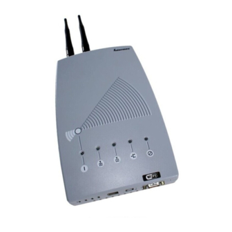
Chapter 1 — Getting Started Understanding the LEDs The WA21 and WA22 have five LEDs. To understand the LEDs during normal use, see the next table. To use the LEDs to help troubleshoot the radios, see “Troubleshooting the Radios” on page 201. - Page 21 Wireless Wireless Ready-to-Work Power Indicator Wired LAN WA21 LEDs: This illustration shows the LEDs that are on the WA21. For help understanding these LEDs, see the LED Descriptions table on the previous page. Power Wireless #1 Wireless #2 Intermec Ready-to-Work...
-
Page 22: Understanding The Ports
MT-RJ connector to connect the access point to your MT-RJ, SC, or ST fiber optic network. To access the ports on the WA21, you must remove the cable access door. To remove the WA21 cable access door 1 Unscrew the two thumbscrews on the cable access door. -
Page 23: How The Access Point Fits In Your Network
WAP. Which Access Point to Use for Your Environment Access Point Environment WA21 Use in locations where an access point is exposed to extreme environments. WA22 Use in most indoor environments. -
Page 24: Using One Access Point In A Simple Wireless Network
Chapter 1 — Getting Started Using One Access Point in a Simple Wireless Network You can use an access point to extend your existing Ethernet network to include wireless end devices. The access point connects directly to your wired network and the end devices provide a wireless extension of the wired LAN. -
Page 25: Example - Configuring An 802.11G Access Point
Root Priority Ethernet Bridging Enabled Checked Intermec recommends that you always implement some type of security. Using Multiple Access Points and Roaming Wireless End Devices For larger or more complex environments, you can install multiple access points so wireless end devices can roam from one access point to another. - Page 26 Chapter 1 — Getting Started Host Ethernet This illustration shows a wireless network with multiple access points. Wireless end devices can roam between the access points to communicate with the host and other end devices. An end device initiates a roam when it attaches to a new access point. The access point sends an attach message to the root access point, which in turn forwards a detach message to the previous access point, allowing each access point to update its forwarding database.
-
Page 27: Example - Configuring An 802.11G Access Point With Roaming End Devices
Chapter 1 — Getting Started Example - Configuring an 802.11g Access Point with Roaming End Devices Host Ethernet In this example, there is one 802.11g radio in each access point. Wireless end devices can roam between the access points to communicate with the host and other end devices. -
Page 28: Using An Access Point As A Wap
Chapter 1 — Getting Started Using an Access Point as a WAP You can extend the range of your wireless network by configuring a dual radio access point as a wireless access point (WAP). The WAP and the wireless end devices it communicates with comprise a secondary LAN. You can position WAPs in strategic locations so they receive data from end devices and then forward the data to the wired network. - Page 29 Chapter 1 — Getting Started WAPs must be on the same IP subnet as the access point. Also, data from wireless end devices should not go through more than three wireless hops before it gets to an access point on the primary LAN. The following procedure explains how to install a simple wireless network with a WAP and roaming end devices.
- Page 30 Chapter 1 — Getting Started a From the main menu, click the link corresponding to the WAP master radio. The radio screen appears. b In the Frequency field, choose the radio frequency of your wireless network. c (802.11a only) In the Allow Wireless Access Points field, choose which service set, if any, you want other WAPs to connect to.
-
Page 31: Example - Configuring An 802.11G Wap With No Roaming End Devices
(Warehouse), LAN ID (11), and frequency as the WAP master radio (802.11g Radio-1). You do not need to configure any secondary LAN settings because the WAP is not connected to a secondary LAN. Intermec recommends that you always implement some type of security. MobileLAN access WA2X System Manual... -
Page 32: Example - Configuring An 802.11A Wap With Roaming End Devices
(Manufacturing), LAN ID (11), and frequency as the access point and WAP radios. You do not need to configure any secondary LAN settings because the WAP is not connected to a secondary LAN. Intermec recommends that you always implement some type of security. MobileLAN access WA2X System Manual... -
Page 33: Using Access Points To Create A Point-To-Point Bridge
Chapter 1 — Getting Started Using Access Points to Create a Point-to-Point Bridge You can use access points to create a point-to-point bridge between two wired LANs. That is, you can have one access point wired to a primary LAN in one building and have a second access point wired to a secondary LAN in another building. - Page 34 Chapter 1 — Getting Started • If you have an 802.11g or 802.11b network and you want the designated bridge to also communicate with wireless end devices (point- to-multipoint), the designated bridge must have two radios. 802.11g radios can communicate with the 802.11b radios and vice versa. The designated bridge master radio parameters must match the end devices radio parameters, and the station radio parameters must match the root master radio parameters.
- Page 35 Chapter 1 — Getting Started 4 (802.11g and 802.11b) Configure the station radio in the designated bridge to communicate with one of the master radio service sets in the point-to-point bridge on the primary LAN: a From the main menu, click the link corresponding to the station radio.
-
Page 36: Example - Configuring An 802.11G Point-To-Point Bridge
Chapter 1 — Getting Started d In the Secondary LAN Flooding field, choose Enabled. 6 Configure the spanning tree settings for the point-to-point bridge on the primary LAN: a From the main menu, click Spanning Tree Settings. The Spanning Tree Settings screen appears. b In the Root Priority field, enter a number other than 0. -
Page 37: Example - Configuring An 802.11A Point-To-Multipoint Bridge
Checked Enabled Secondary LAN Bridge Priority Secondary LAN Disabled Enabled Flooding Intermec recommends that you always implement some type of security. Example - Configuring an 802.11a Point-to-Multipoint Bridge Primary LAN Secondary LAN Host Root Designated bridge In this example, each access point only has one 802.11a radio. Since the 802.11a radio can function as a master and a station, wireless end devices can communicate with either access point. -
Page 38: Using Dual Radio Access Points For Redundancy
Disabled Enabled Flooding Intermec recommends that you always implement some type of security. Using Dual Radio Access Points for Redundancy You can configure WA21s and WA22s that have two 802.11g radios, two 802.11b radios or two 802.11a radios to provide redundancy for your network. -
Page 39: Configuring The Access Point (Setting The Ip Address)
Chapter 1 — Getting Started Host Ethernet In this example, AP3 is a dual radio access point. It may be located on a loading dock or other remote location. During normal operations, AP3 functions as a normal access point, transmitting frames to and from the host. However, if the Ethernet connection is disrupted, AP3 can function as a WAP and continue operations by transmitting frames to a master radio in AP1. -
Page 40: Using The Mobilelan Access Utility
Start menu, choose Run. In the Open field, type , where X is the CD-ROM drive. X:\INDEX.HTM Or use a web browser to navigate to www.intermec.com. From the Service & Support menu, click Downloads. Choose Wireless: MobileLAN access Utility to download the MobileLAN access Utility. -
Page 41: Using A Communications Program
• an RS-232 null-modem cable. One end of this cable must be a 9-pin socket connector to connect to the serial port on the access point. Intermec offers a 9-socket to 9-socket null-modem cable (P/N 059167). To order this cable, contact your local Intermec representative. - Page 42 PC screen. The Username field appears. 5 In the Username field type the default user name , and then Intermec press Enter. The user name is case sensitive. 6 In the Password field type the default password , and then Intermec press Enter.
- Page 43 Chapter 1 — Getting Started 7 Press Enter to access the TCP/IP Settings menu. 8 If you are not using a DHCP server, you need to manually assign an IP address. Configure these parameters in the TCP/IP Settings menu: A unique IP address. IP Address IP Subnet Mask The subnet mask that matches the other devices in your...
-
Page 44: Using A Web Browser Interface
The Access Point Login screen appears. 4 If necessary, enter a user name and a password. The default user name is Intermec and the default password is Intermec. You can define a user name and password. For help, see “Setting Up Logins” on page 140. -
Page 45: Using A Telnet Session
Chapter 1 — Getting Started 5 Click Login. The TCP/IP Settings screen appears. Your web browser session is established. Note: Although you can use several different methods to manage the access point remotely, this manual assumes you are using a web browser. Using a Telnet Session After you have set the initial IP address, you can configure, manage, and troubleshoot the access point from a remote location using a telnet session. - Page 46 Chapter 1 — Getting Started 3 If necessary, enter the user name and press Enter. Then, enter the password and press Enter. The default user name is Intermec and the default password is Intermec. You can define a user name and password.
-
Page 47: Saving Configuration Changes
Chapter 1 — Getting Started Saving Configuration Changes As you are configuring the access point, you may want to move your changes to the saved or active configuration file. As you hover over fields, the footer bar shows you the saved value, active value, and default value. When you are done configuring the access point, you may want to activate your changes immediately or you may want to save the changes now and activate them later. -
Page 48: Using A Web Browser Interface
Chapter 1 — Getting Started Using a Web Browser Interface 1 On the menu bar, click Save/Discard Changes. This screen appears. Click to use your new configuration the next time Click to use your you reboot the new configuration access point. now. -
Page 49: Installing The Access Points
This chapter covers these topics: • Installation guidelines • Installing the WA21 • Installing the WA22 • Connecting to your fiber optic network • Connecting power over Ethernet •... -
Page 50: Installation Guidelines
Installation Guidelines Intermec recommends that you have an Intermec-certified RF specialist conduct a site survey to determine the ideal locations for all your Intermec wireless network devices. To conduct a proper site survey, you need to have special equipment and training. -
Page 51: Other Access Points
2 Mount the WA21. For help, see the MobileLAN access WA21 Quick Start Guide and the instructions that shipped with the bracket kit. 3 Connect the WA21 to your wired LAN (unless you are using it as a WAP). For help, see “Connecting the WA21 to Your Wired LAN” on page 38. -
Page 52: Connecting The Wa21 To Your Wired Lan
Chapter 2 — Installing the Access Points Connecting the WA21 to Your Wired LAN Unless you are using the WA21 as a WAP, you need to connect it to your Ethernet or fiber optic network. To connect the WA21 to your fiber optic network, you must have a WA21 with the fiber optic option. -
Page 53: Installing The Wa22
• Cubicle bracket kit (P/N 069926) • Locking bracket kit (P/N 070184) To order one of these kits, contact your Intermec representative. Intermec also offers a variety of antennas and antenna accessories. For more information, see “Antennas and Antenna Accessories” on page 251. -
Page 54: Connecting To Your Fiber Optic Network
You can order your access points with a fiber optic option. Using appropriate patch cords and an adapter (as described in the next section), you can connect your WA21 and WA22 to: • an MT-RJ network. • a square connector (SC) network. -
Page 55: Connecting To An Mt-Rj Network
MT-RJ, SC, or ST. Patch cords and adapters are available from many different manufacturers. For help choosing the proper patch cord and adapter, contact your local Intermec representative. Note: All cables must be multimode, 62.5/125 µm. Connecting to an MT-RJ Network To connect to an MT-RJ network, you need: •... -
Page 56: Connecting To An Sc Network
Chapter 2 — Installing the Access Points Connecting to an SC Network To connect to an SC network, you need: • a patch cord with a female MT-RJ connector to insert into the access point’s male MT-RJ fiber optic port, and an SC connector to insert into the SC adapter. -
Page 57: Connecting To An St Network
Chapter 2 — Installing the Access Points Female MT-RJ connector SC connector SC adapter SC connector Patch cord To SC network To SC network Note: The patch cord shown above must connect to the access point with a female MT-RJ connector. For details, see “Using and Purchasing the Required Patch Cord and Adapter”... -
Page 58: Connecting Power Over Ethernet
Required Patch Cord and Adapter” on page 40. Connecting Power Over Ethernet The WA22 is powered by power over Ethernet. The WA21 can be powered by AC power or by power over Ethernet or both. For all access points, you need a power bridge. For a list of the power bridges that Intermec sells, contact your local Intermec representative. -
Page 59: Antenna Guidelines
Therefore, the exact range that you will achieve with each access point is difficult to determine. Intermec recommends that you allow an Intermec-certified RF specialist to perform a site survey before you install a wireless network. For more information, contact your local Intermec representative. -
Page 60: Positioning Antennas For Dual Radio Access Points
Identifying the Radios and the Radio Ports: The left illustration shows the antenna ports on a WA21; the right illustration shows the antenna ports on a WA22. For the 802.11g radio and the 802.11b radio, the primary port is a transmit/receive port and the secondary port is a receive-only port. - Page 61 Chapter 2 — Installing the Access Points Note these important points: • Position omni antennas for the radios at least 0.61 m (2 ft) apart. • Position directional antennas so they point in the same direction. • Position the antennas so that both antennas are within range of the radios they need to communicate with.
-
Page 62: About Antenna Diversity For 802.11G Radios
Chapter 2 — Installing the Access Points About Antenna Diversity for 802.11g Radios The 802.11g radios support antenna diversity, but it is not automatically enabled. You must manually enable this feature using the Access Point Configuration menu. From the main menu, click 802.11g Radio > Advanced Configuration. -
Page 63: Configuring The Ethernet Network
Configuring the Ethernet Network This chapter explains how to configure the MobileLAN access WA2X family of access points so that they communicate with your Ethernet network. This chapter explains: • Configuring the TCP/IP settings • Configuring other Ethernet or fiber optic settings MobileLAN access WA2X System Manual... -
Page 64: Configuring The Tcp/Ip Settings
Chapter 3 — Configuring the Ethernet Network Configuring the TCP/IP Settings If you are using a DHCP server to automatically assign an IP address to the access point, go to “Configuring the Access Point as a DHCP Client” on page 51. If you are not using a DHCP server, you need to manually assign some TCP/IP parameters. -
Page 65: Configuring The Access Point As A Dhcp Client
Chapter 3 — Configuring the Ethernet Network TCP/IP Settings Descriptions Parameter Explanation IP Address Enter the IP address of the access point. The IP address has the form x.x.x.x, where x is a number from 0 to 255. IP Subnet Mask Enter the subnet mask that matches the other devices in your network. - Page 66 Chapter 3 — Configuring the Ethernet Network Note: You cannot configure the access point as both a DHCP server and a DHCP client. Note: If you are using the embedded authentication server feature, do not configure the access point as a DHCP client. To configure the access point as a DHCP client 1 From the menu, click TCP/IP Settings.
- Page 67 Chapter 3 — Configuring the Ethernet Network DHCP Client Parameter Descriptions Parameter Explanation DHCP Mode To configure the access point as a DHCP client, you must choose one of these options: Always Use DHCP: The access point uses DHCP after every reboot whether or not an infinite lease was granted in a previous session.
-
Page 68: Configuring The Access Point As A Dhcp Server
Chapter 3 — Configuring the Ethernet Network Configuring the Access Point as a DHCP Server You can configure the access point as a simple DHCP server that provides DHCP server functions for small installations where no other DHCP server is available. The DHCP server will offer IP addresses and other TCP/IP settings to any DHCP client it hears as long as a pool of unallocated IP addresses is available. - Page 69 Chapter 3 — Configuring the Ethernet Network 2 Verify that the IP Address field, IP Subnet Mask field, and IP Router field are configured. For help, see “Configuring the TCP/IP Settings” on page 50. 3 Configure the DHCP parameters to make this access point a DHCP server.
- Page 70 Chapter 3 — Configuring the Ethernet Network 6 Configure the DHCP server. For help, see the next table. 7 Click Submit Changes to save your changes. To activate your changes, from the menu bar click Save/Discard Changes, and then click Save Changes and Reboot.
-
Page 71: Supported Dhcp Server Options
Chapter 3 — Configuring the Ethernet Network DHCP Server Setup Parameter Descriptions (continued) Parameter Explanation Display-only parameters IP Subnet Mask Displays the subnet mask entered at the TCP/IP Settings screen. IP Router Displays the address of the IP Router. (Gateway) DNS Address 1 Displays the IP address of the Domain Name Server. -
Page 72: Configuring The Access Point To Send Arp Requests
Chapter 3 — Configuring the Ethernet Network If the destination subnet is a different subnet from the one the access point is on, the destination MAC address is changed to the IP router that has been configured for the access point. If the destination subnet is the same subnet as the one the access point is on, the access point converts the MAC address to the MAC address that belongs to the destination IP address. -
Page 73: Configuring Other Ethernet Or Fiber Optic Settings
Chapter 3 — Configuring the Ethernet Network querying routers. The auto ARP minutes parameter controls the time interval between ARP requests. If the address of the IP router is 0.0.0.0, then the access point sends an ARP request to its own IP address. Without this option, an access point might not use its IP address for extended periods of time and the IP address would expire from the router ARP table. -
Page 74: Configuring The Ethernet Address Table
Chapter 3 — Configuring the Ethernet Network 2 Configure the parameters. For help, see the next table. 3 Click Submit Changes to save your changes. To activate your changes, from the menu bar click Save/Discard Changes, and then click Save Changes and Reboot. -
Page 75: Configuring Ethernet Filters
Ethernet frame type filter and predefined subtype filter settings override customizable subtype filter settings. However, Intermec recommends that when creating customizable subtype filters, you do not duplicate existing frame type or predefined subtype filters or unexpected results may occur. -
Page 76: Using Ethernet Frame Type Filters
Chapter 3 — Configuring the Ethernet Network Using Ethernet Frame Type Filters You can define filters for common networking protocols such as IP, Novell IPX, and 802.2 LLC. You can also set filters that will pass only those Ethernet frame types found on your network. You can set the default action for general and specific frame types. -
Page 77: Using Predefined Subtype Filters
Chapter 3 — Configuring the Ethernet Network 2 For each frame type field, check or clear the Allow/Pass check box to configure if the frame types are allowed to pass or are dropped. If you check the check box, the frame type is allowed to pass. For help, see the next table. -
Page 78: Customizing Subtype Filters
Chapter 3 — Configuring the Ethernet Network 2 For each frame subtype field, check or clear the Allow/Pass check box to configure if the frame subtypes are allowed to pass or are dropped. If you check the check box, the frame subtype is allowed to pass. 3 Click Submit Changes to save your changes. - Page 79 Chapter 3 — Configuring the Ethernet Network 2 For each subtype field, check or clear the Allow/Pass check box to configure if the subtypes are allowed to pass or are dropped. If you check the check box, the subtype is allowed to pass. 3 In the SubType field, choose the customizable frame subtype.
-
Page 80: Configuring Advanced Filters
You can use filter values and filter expressions to minimize network traffic over the wireless links; however, Intermec recommends that you use advanced Ethernet filters only if you have an extensive understanding of network frames and their contents. Use other existing filters whenever possible. - Page 81 Chapter 3 — Configuring the Ethernet Network Setting Filter Values You can associate an ID with a pattern value by selecting a filter and then entering an ID and a value. All values with the same value ID belong to the same list.
- Page 82 Chapter 3 — Configuring the Ethernet Network 2 Configure the filter expressions parameters. For help, see the next table. 3 Click Submit Changes to save your changes. To activate your changes, from the menu bar click Save/Discard Changes, and then click Save Changes and Reboot.
- Page 83 Chapter 3 — Configuring the Ethernet Network Filter Expressions Parameter Descriptions (continued) Parameter Explanation Value ID Represents a value in the Filter Values menu. The bytes after the frame offset are compared to the data pattern indicated by the value. Value ID can be from 0 to 255 and must match one or more value IDs in the Filter Values menu.
- Page 84 Chapter 3 — Configuring the Ethernet Network For this example, set these filter expressions. Example 1 – Filter Expressions Parameter Value Explanation ExprSeq The order that you want the expressions executed. You must have an expression for each Value ID that is listed in the Filter Values menu.
- Page 85 Chapter 3 — Configuring the Ethernet Network You must enter a filter expression for each Value ID in the Filter Values menu. In this example, only the ExprSeq value and the Value ID value change. Example 2 This example shows how to use Ethernet filters to discard all DIX IP multicast frames except those from selected devices.
- Page 86 Chapter 3 — Configuring the Ethernet Network Set the first filter expression as shown below. Example 2 – First Filter Expression Parameter Value Explanation ExprSeq The first expression that is executed. You must have an expression for each Value ID that is listed in the Filter Values menu.
- Page 87 Chapter 3 — Configuring the Ethernet Network Set the second filter expression as shown below. Example 2 – Second Filter Expression Parameter Value Explanation ExprSeq The second expression that is executed. Offset Checks for the DIX IP frame type, which starts 12 bytes from the destination address.
- Page 88 Chapter 3 — Configuring the Ethernet Network Set the third filter expression as shown below. Example 2 – Third Filter Expression Parameter Value Explanation ExprSeq The third expression that is executed. Offset Checks the source Ethernet address, which starts 6 bytes from the destination address.
-
Page 89: Configuring The Radios
Configuring the Radios This chapter explains how to configure the radios in the MobileLAN access WA2X family of access points so that they communicate with your wireless end devices. This chapter covers these topics: • About the Radios • Configuring the 802.11g radio •... -
Page 90: About The Radios
In active scanning, an end device sends a probe request to the SSID that it wants to associate with. Intermec’s newer end devices with newer 802.11g radios (such as the CK30 and CV60) work in a mixed security environment. - Page 91 Chapter 4 — Configuring the Radios End devices that perform passive scanning do not support a mixed security environment. In passive scanning, an end device listens for beacons (sent by the access point radio’s primary service set), picks one it likes, and then associates with it.
- Page 92 Chapter 4 — Configuring the Radios 802.11g Radio Parameter Descriptions Parameter Explanation Frequency Choose the frequency that this access point uses to transmit and receive frames. The available frequencies depend on the country (Master radio only) and the radio option configured on the access point. See the “Worldwide Frequencies for 802.11g and 802.11b Radios”...
- Page 93 2484* * Currently, not available for the 802.11g radios. If you need availability, contact your local Intermec representative. The 802.11g and 802.11b channels that are allowed in a given country may change without notice. Be sure you use only those frequencies that are permissible in the given country.
-
Page 94: Configuring 802.11G Radio Advanced Parameters
Chapter 4 — Configuring the Radios Configuring 802.11g Radio Advanced Parameters You can configure advanced parameters for the 802.11g radio primary service set. These settings are shared by any secondary service sets defined for the radio. To configure advanced parameters 1 From the main menu, click 802.11g Radio >... - Page 95 Chapter 4 — Configuring the Radios 802.11g Radio Advanced Parameter Descriptions Parameter Description Client Specifies if this radio will communicate with 802.11b and/or Type/Performance 802.11g radios: 11b/11g with range reliability (Not Wi-Fi): Default setting. Primarily used for 802.11b clients that can only support up to 2 Mbps rate.
- Page 96 Determines if you want the radio to drop to a slower data rate Fallback when it has trouble communicating with another radio. Intermec recommends that you leave this check box checked or you may affect radio network performance. Clearing this check box is only used when performing site surveys.
-
Page 97: Configuring 802.11G Radio Inbound Filters
Chapter 4 — Configuring the Radios Configuring 802.11g Radio Inbound Filters You can configure inbound filters for the 802.11g radio primary service set. These settings are shared by any secondary service sets defined for the radio. You can filter different types of wireless traffic that it may receive. You may want to use this feature by itself or with an access control list (ACL) to help secure your network. -
Page 98: Applying Hot Settings
Determines if this radio accepts UDP Plus frames from end (UDP/IP Port 5555) devices. The UDP Plus frames must match the UDP network port 5555 on the DCS 30X, Intermec Gateway, or ARP. Allow DHCP Determines if this radio accepts DHCP frames. The DHCP frames must match UDP destination port 67 and ARP. -
Page 99: Configuring The 802.11G Radio To Communicate With A Spectralink Network
Chapter 4 — Configuring the Radios Configuring the 802.11g Radio to Communicate With a SpectraLink Network SpectraLink wireless telephone systems simplify network infrastructure and network management by combining voice and data traffic over one wireless network. The 802.11g radio can communicate the SpectraLink network. - Page 100 Chapter 4 — Configuring the Radios To configure the 802.11b radio 1 From the main menu, click 802.11b Radio. The 802.11b Radio screen appears. 2 Configure the parameters for the radio. For help, see the next table. 3 Configure the advanced parameters for the radio. For help, see “Configuring 802.11b Radio Advanced Parameters”...
-
Page 101: Configuring 802.11B Radio Advanced Parameters
Chapter 4 — Configuring the Radios 802.11b Radio Parameter Descriptions (continued) Parameter Explanation Frequency Choose the frequency within the 2.4 to 2.5 GHz range that this access point uses to transmit and receive frames. The available (Master radio only) frequencies are country-dependent and are determined by the radio. - Page 102 Determines if you want the radio to drop to a slower data rate Fallback when it has trouble communicating with another radio. Intermec recommends that you leave this check box checked or you may affect radio network performance. Clearing this check box is only used when performing site surveys.
-
Page 103: Configuring 802.11B Radio Inbound Filters
Chapter 4 — Configuring the Radios 802.11b Radio Advanced Parameter Descriptions (continued) Parameter Description Data/Voice Settings Choose the setting that optimizes the wireless network: (Master radio only) Data Traffic Only: The access point transmits only data traffic. Data and SpectraLink Traffic: The access point transmits both data and voice traffic. - Page 104 Determines if this radio accepts UDP Plus frames from end (UDP/IP Port 5555) devices. The UDP Plus frames must match the UDP network port 5555 on the DCS 30X, Intermec Gateway, or ARP. Allow DHCP Determines if this radio accepts DHCP frames. The DHCP frames must match UDP destination port 67 and ARP.
-
Page 105: Configuring A Spectralink Network
Chapter 4 — Configuring the Radios Configuring a SpectraLink Network SpectraLink wireless telephone systems simplify network infrastructure and network management by combining voice and data traffic over one wireless network, leveraging 802.11b wireless LAN technology. You use your SpectraLink telephone to make and receive calls, just like a regular telephone, subject to the restrictions of your PBX. -
Page 106: Configuring The 802.11A Radio
In active scanning, an end device sends a probe request to the SSID that it wants to associate with. Intermec’s newer end devices with newer 802.11g radios (such as the CK30 and CV60) work in a mixed security environment. - Page 107 Chapter 4 — Configuring the Radios For details, see “When You Configure Different SSIDs With Different Security Settings” on page 136. To configure the 802.11a radio 1 From the main menu, click 802.11a Radio. The 802.11a Radio screen appears. 2 Configure the parameters for the radio. For help, see the next table. 3 Configure the advanced parameters for the radio.
- Page 108 Chapter 4 — Configuring the Radios 802.11a Radio Parameter Descriptions Parameter Explanation Frequency Choose the frequency within the 5.15 to 5.35 GHz range that this access point uses to transmit and receive frames. You can (Master radio only) also set the frequency to Dynamic, which lets the access point choose the best available channel to use.
-
Page 109: Configuring 802.11A Radio Advanced Parameters
Chapter 4 — Configuring the Radios Worldwide Frequencies for the 802.11a Radio Channel ETSI France Japan Israel 5180 (default) 5200 5210 Turbo 5220 5240 5250 Turbo 5260 (default) 5280 5290 Turbo 5300 5320 • Channels marked with an asterisk (*) are not available in the mid-range radio. - Page 110 Determines if you want the radio to drop to a slower data rate Fallback when it has trouble communicating with another radio. Intermec recommends that you leave this check box checked or you may affect radio network performance. Clearing this check box is only used when performing site surveys.
-
Page 111: Configuring 802.11A Radio Inbound Filters
Chapter 4 — Configuring the Radios 802.11a Radio Advanced Parameter Descriptions (continued Parameter Description Disallow SSID Determines if end devices that have their SSID (Network Name) set to ANY or are left blank can associate with this access point. (Network Name) of ‘ANY’... - Page 112 Determines if this radio accepts UDP Plus frames from end (UDP/IP Port 5555) devices. The UDP Plus frames must match the UDP network port 5555 on the DCS 30X, Intermec Gateway, or ARP. Allow DHCP Determines if this radio accepts DHCP frames. The DHCP frames must match UDP destination port 67 and ARP.
-
Page 113: Configuring The Spanning Tree
Configuring the Spanning Tree This chapter explains how to configure the MobileLAN access WA2X family of access points so that they create a spanning tree topology. This chapter covers these topics: • About the access point spanning tree • Configuring the spanning tree parameters •... -
Page 114: About The Access Point Spanning Tree
This spanning tree contains a root access point on the primary LAN and a designated bridge on the secondary LAN. Within the spanning tree, access points use Intermec’s IAPP (Inter Access Point Protocol) or secure IAPP to communicate with each other across the Ethernet network, over wireless secondary LANs, and through IP tunnels to remote IP subnets. -
Page 115: About The Primary Lan And The Root Access Point
• The root should have the latest software release available because the root distributes parameters to the child access points. In a mixed network of WA2Xs and 210Xs, choose a WA21 or WA22 as the root. • If your mixed network contains MobileLAN access products and 6710s, configure a MobileLAN access product as the root. -
Page 116: About Secondary Lans And Designated Bridges
LAN. • The designated bridge should have the latest software release available. In a mixed network of WA2Xs and 210Xs, choose a WA21 or WA22 as the designated bridge. • The designated bridge must be configured so that the Secondary LAN Bridge Priority value is a non-zero number. -
Page 117: About Ethernet Bridging/Data Link Tunneling
Turning off Ethernet bridging enables data link tunneling. The data link tunneling mode causes the child access point to encapsulate inbound wireless data into an Intermec-assigned 875C frame. This data frame is then forwarded via the Ethernet port to the next access point on the path, and so on, until the frame reaches the root access point or designated bridge. - Page 118 Chapter 5 — Configuring the Spanning Tree When should you use data link tunneling? • Use data link tunneling if you have Ethernet switches that do not support the IEEE 802.1d requirements for backward learning. Some proprietary VLAN switches and ATM LANE bridges do not support this standard.
-
Page 119: About Routable And Non-Routable Network Protocols
IP subnets. Some Intermec wireless end devices use the Intermec NNL protocol, which is a simple Non-routable Network Layer protocol. This NNL protocol is used to carry high-layer data in a local area network environment. - Page 120 Chapter 5 — Configuring the Spanning Tree 2 Configure the spanning tree parameters. For help, see the next table. 3 Click Submit Changes to save your changes. To activate your changes, from the menu bar click Save/Discard Changes, and then click Save Changes and Reboot.
- Page 121 VLANs to specific ports. You should clear this check box for a static configuration. Rightmost LED Determines if this LED behaves as if it were an Intermec Ready- Behavior to-Work indicator or a legacy Root/error indicator. Choosing Spanning Tree Root Indicator causes the LED to blink if the access point is configured as the root and remain on if an error is detected.
-
Page 122: About Ip Tunnels
Chapter 5 — Configuring the Spanning Tree Spanning Tree Parameter Descriptions (continued) Parameter Explanation Secondary LAN Appears for Designated Bridge only. Flooding Specifies the types of frames it forwards from the primary LAN (Outbound) to the secondary LAN: Disabled: No flooding occurs unless the root access point (in the Global Flooding screen) enables the Multicast or Unicast Outbound to Secondary LANs parameter. - Page 123 Chapter 5 — Configuring the Spanning Tree Host Root Primary LAN (root IP subnet) IP router IP network Designated IP router bridge Secondary LAN (remote IP subnet) Only one IP tunnel can exist between the root access point and an access point (usually the designated bridge) on a remote IP subnet.
-
Page 124: Creating Ip Tunnels
Chapter 5 — Configuring the Spanning Tree When an access point at the endpoint of the IP tunnel receives data from an end device, it uses a standard IP protocol called Generic Router Encapsulation (GRE) to encapsulate the data into a frame. These encapsulated IP/GRE frames use normal IP routing to pass through IP routers to the root access point. - Page 125 Chapter 5 — Configuring the Spanning Tree To create a unicast IP tunnel 1 Make sure that end devices that will roam between the root IP subnet and the remote IP subnet have IP addresses from the root IP subnet and have their default router set the same as the root access point.
-
Page 126: Using One Ip Multicast Address For Multiple Ip Tunnels
Access points can act as IP hosts and participate in an IP multicast group by enabling IGMP. The Internet Assigned Numbers Authority has allocated 224.0.1.65 for Intermec’s IAPP. You must enter this address in the IP address list in the root access point (the address list may contain other IP addresses) and in the Multicast Address field in the other access points. -
Page 127: How Frames Are Forwarded Through Ip Tunnels
5 On the access point at the endpoint of the IP tunnel, set the Mode parameter to Listen. 6 On the root access point, click IP Tunnels > IP Addresses. Enter the Intermec multicast address 224.0.1.65. 7 On the access point at the end of the IP tunnel, check the Enable IGMP check box. -
Page 128: Outbound Frames
Chapter 5 — Configuring the Spanning Tree Outbound Frames Frames are forwarded outbound (to a secondary LAN) through an IP tunnel if: • an end device is known to be attached to an access point on a remote IP subnet. •... -
Page 129: Frame Types That Are Never Forwarded
Chapter 5 — Configuring the Spanning Tree MAC frames that are forwarded inbound are encapsulated by the access point at the remote end of the IP tunnel, forwarded through the IP tunnel to the root access point, unencapsulated, and placed on the network. Frame Types That Are Never Forwarded Certain frame types are never forwarded through IP tunnels. -
Page 130: Configuring Ip Tunnels
Chapter 5 — Configuring the Spanning Tree Configuring IP Tunnels For guidelines, see “About IP Tunnels” on page 108. To configure the IP Tunnels screen 1 From the main menu, click IP Tunnels. The IP Tunnels screen appears. 2 Configure the IP tunnels parameters. For help, see the next table. 3 Click Submit Changes to save your changes. -
Page 131: Configuring The Ip Address List
IP address in the root access point’s IP address list. The Internet Assigned Numbers Authority has allocated 224.0.1.65 for Intermec’s inter-access-point protocol (IAPP). Configuring the IP Address List On the root access point and root candidates, the IP address list contains the IP addresses or DNS names of all the access points at the endpoint of the IP tunnels. -
Page 132: Configuring Ip Tunnel Filters
Chapter 5 — Configuring the Spanning Tree Configuring IP Tunnel Filters You can set both Ethernet and IP tunnel filters, and you can create protocol filters for predefined protocol types. In addition, you can define arbitrary frame filters based on frame content. By default, all IP tunnel traffic (except NNL traffic) is dropped. - Page 133 Chapter 5 — Configuring the Spanning Tree Scope: Set scope to Unlisted or All. If you select All, then all frames of that type are unconditionally passed or dropped, depending on the action you specified. If you select Unlisted, then frames are passed or dropped only if the frame type is not listed in the predefined or customizable tables.
-
Page 134: Using Predefined Subtype Filters
Chapter 5 — Configuring the Spanning Tree Frame Type Filter Descriptions Frame Type Explanation DIX IP TCP Ports Primary Internet Protocol Suite (IP) transport protocols. DIX IP UDP Ports SNAP IP TCP Ports SNAP IP UDP Ports DIX IP Other Protocols IP protocols other than TCP or User Datagram SNAP IP Other Protocols Protocol (UDP). -
Page 135: Customizing Subtype Filters
Chapter 5 — Configuring the Spanning Tree 2 For each frame subtype field, check or clear the check box to configure if the frame subtypes are passed or are dropped. If you check the check box, the frame subtype is allowed to pass. 3 Click Submit Changes to save your changes. - Page 136 Chapter 5 — Configuring the Spanning Tree 2 For each frame subtype field, check or clear the Allow/Pass check box to configure if the frame subtypes are passed or are dropped. If you check the check box, the frame subtype is allowed to pass. 3 In the SubType field, choose the customizable frame subtype.
-
Page 137: Filter Examples
Chapter 5 — Configuring the Spanning Tree Filter Examples These examples illustrate how to set both Ethernet and IP tunnel filters to optimize network performance. The next illustration includes: • wireless end devices using TCP/IP to communicate with other devices. •... -
Page 138: Example 1
Chapter 5 — Configuring the Spanning Tree Example 1 The root (AP1), AP3, AP5, and AP6 service only wireless end devices. These access points need to pass IP traffic, but not pass IPX traffic that does not need to be forwarded to the primary or secondary LAN. For this example, set these options on the Ethernet Frame Type Filters screen. - Page 139 Chapter 5 — Configuring the Spanning Tree For this example, set these options on the Ethernet Frame Type Filters screen. In the Predefined Subtype Filters screen, set the 802.2-IPX-RIP field to drop 802.2, DIX, and 802.3 frames. MobileLAN access WA2X System Manual...
-
Page 140: Example 3
Chapter 5 — Configuring the Spanning Tree Example 3 If you have a DHCP server on a Windows NT server and you want to use this DHCP server to assign TCP/IP parameters to end devices on a remote IP subnet, you need to set these filters to allow for the necessary IP tunneling. -
Page 141: Configuring Global Parameters
Chapter 5 — Configuring the Spanning Tree IP Tunnels and Mobile IP Comparison Issue IP Tunneling Mobile IP Software compatibility No changes are required to existing IP Requires a mobile IP client software stack software stacks in end devices. in end devices. Addressing limitations for Requires that end device IP addresses None. - Page 142 Chapter 5 — Configuring the Spanning Tree ARP requests are multicast frames that are periodically sent out to all devices on the Ethernet network. An ARP cache is a table of known MAC addresses and their IP addresses that the access point maintains. When an access point receives an ARP request, it checks its ARP cache to determine if the destination end device’s IP address is known.
- Page 143 Chapter 5 — Configuring the Spanning Tree Global Flooding Parameter Descriptions (continued) Parameter Explanation Multicast Outbound Appears only if Multicast Flooding is enabled. to Secondary LANs Specifies if outbound multicast frames with unknown destination addresses are flooded toward secondary LANs: Enabled: The root access point controls flooding for all the designated bridges on secondary LANs.
-
Page 144: Configuring Global Rf Parameters
Chapter 5 — Configuring the Spanning Tree Global Flooding Parameter Descriptions (continued) Parameter Explanation Enable ARP Flooding • the destination end device is not known, the access point (continued) forwards the ARP request based on its flooding and filtering settings. If you disable ARP flooding, the access point ignores ARP requests for destination end devices that are not in its ARP cache. - Page 145 Chapter 5 — Configuring the Spanning Tree Global RF Parameter Descriptions Parameter Explanation Perform Determines how the access point will handle the conversion of RFC1042/DIX RFC1042/DIX frames that are received on its radio ports. Conversion Check this check box if the frames that are received and have a protocol type equal to a value in the “RFC1042 types to pass through”...
- Page 146 Chapter 5 — Configuring the Spanning Tree MobileLAN access WA2X System Manual...
-
Page 147: Configuring Security
Configuring Security This chapter explains how to use different security solutions to ensure that you have a secure wireless network. This chapter covers these topics: • Understanding security • Controlling access to access point menus • Creating a secure spanning tree •... -
Page 148: Understanding Security
1 Change the SSID from its default value of INTERMEC and check the Disallow Network Name of ‘ANY’ check box. For help, see Chapter 4, “Configuring the Radios.”... - Page 149 Chapter 6 — Configuring Security 3 Use a password server to maintain a list of authorized users who can configure and manage the access points. You can either use an external RADIUS server or you can use any access point’s embedded authentication server (EAS).
-
Page 150: When You Configure Different Ssids With Different Security Settings
If the end device’s security setting does not match the probe request’s security bit, the end device cannot associate. Intermec’s newer end devices with newer 802.11g radios (such as the CK30 and CV60) work in a mixed security environment. -
Page 151: When You Include Multiple Radius Servers On The Radius Server List
Chapter 6 — Configuring Security For example, you have an access point with an 802.11g radio. You configure the primary service set for WPA-PSK and the secondary 1 service set with no security. An end device with an 802.11b radio is configured with no security and you may expect it to associate with the secondary 1 service set. -
Page 152: Controlling Access To Access Point Menus
Chapter 6 — Configuring Security For example, a company has a corporate office and a remote distribution center. At each location, the local users have an SSID and security settings that match their local RADIUS server. When users travel to the other site, they still authenticate to their local RADIUS server. - Page 153 Chapter 6 — Configuring Security All access methods are enabled by default. You may want to disable any of these methods that you will not use to prevent access by an unauthorized method. To enable or disable access methods 1 From the main menu, click Security. The Security screen appears. 2 Enable or disable the access methods that users can use to connect to the access point.
-
Page 154: Setting Up Logins
Chapter 6 — Configuring Security Security Parameter Descriptions (continued) Parameter Description Allow TFTP Access Determines if users can use TFTP clients to exchange files with (Read-Only) the access point. Allow ICMP Determines if users can use the MobileLAN access Utility or Configuration another program that uses ICMP echo (PING) to set the IP address or restore factory defaults on this access point. -
Page 155: Configuring The Access Point To Use A Password Server
Chapter 6 — Configuring Security Configuring the Access Point to Use a Password Server If you use a password server to manage users who can log in to this access point, you need to tell this access point how to communicate with the password server and then you need to configure the password server. -
Page 156: Changing The Default Login
Chapter 6 — Configuring Security 7 Configure the password server database: • In the EAS database, in the Type field choose Login and then enter the user name and password for each login. For help, see Chapter 7, “Configuring the Embedded Authentication Server (EAS).” •... -
Page 157: Creating A Secure Spanning Tree
The three authentication methods that you can use to secure the spanning tree are: Simple Wireless Authentication Protocol (SWAP), TTLS, or TLS. SWAP is an Intermec proprietary protocol that is based on the EAP-MD5 challenge. Since it requires less processing power, it requires less memory and you can use it on all access points. - Page 158 Chapter 6 — Configuring Security When deciding on which type of spanning tree security to use, the supplicant access point and the authenticator will negotiate an authentication method that can be used by both. If the Allow SWAP check box is checked on both access points, SWAP will always be used. If the Allow SWAP check box is cleared on one or both of the access points, either TTLS or TLS will be used, depending on the setting of the Preferred Protocol field of the supplicant access point.
-
Page 159: Enabling Secure Communications Between Access Points And End Devices
Chapter 6 — Configuring Security 2 Check the Secure IAPP check box. 3 Click Submit Changes to save your changes. 4 In the IAPP Secret Key field, enter a secret key. This secret key must be between 16 and 32 bytes. 5 Determine how the access points authenticate to the network: •... -
Page 160: Using An Access Control List (Acl)
Chapter 6 — Configuring Security Using an Access Control List (ACL) You can use an access control list (ACL) that contains the MAC addresses that are authorized to communicate with the network through the access point. The end devices do not need any special client software. To use the ACL, you must have: •... - Page 161 Chapter 6 — Configuring Security 4 Normally, the access point issues RADIUS requests with the user name and password of the end device that is trying to communicate with the network. Check the Enable Alternative Method ACL check box if you want the access point to issue RADIUS requests with the user name and password both set to the MAC address of the end device that is trying to communicate with the network.
-
Page 162: Configuring Vlans
Chapter 6 — Configuring Security Configuring VLANs Virtual LANs (VLANs) make it easy to create and manage logical groups of wireless end devices that communicate as if they were on the same LAN. You can group all wireless users on a particular VLAN in order to manage the IP address space differently. - Page 163 Chapter 6 — Configuring Security 2 Check or clear the Enable GVRP for VLAN check box. • Check the check box if the VLAN switch is configured to dynamically configure its ports based on the end devices’ needs. • Clear the check box if the VLAN switch is statically configured to always forward specific VLANs to specific ports.
-
Page 164: Configuring Wep 64/128/152 Security
Since static WEP keys can be difficult to update, the MobileLAN access products and other Intermec products let you enter up to four WEP keys, and then pick a WEP transmit key (1-4). It is easier to rotate the WEP transmit key than to individually change all the WEP keys. - Page 165 Chapter 6 — Configuring Security 2 In the Security Level field, select Static WEP. 3 Click Submit Changes to save your changes. This screen appears. 4 Configure the parameters for WEP configuration. To ensure maximum security, configure each WEP key with a different WEP code. For help, see the next table.
-
Page 166: Implementing An 802.1X Security Solution
802.1x-enabled end devices, contact your local Intermec representative. • A trusted certificate authority (CA), which issues digital authentication certificates. Intermec and others can provide the service of acting as a CA and can issue certificates. For more information, contact your local Intermec representative. -
Page 167: Configuring The Access Point As An Authenticator
Chapter 6 — Configuring Security • The authentication server and end devices with supplicants need certificates. A CA certificate is the root certificate or public key. A server certificate (sometimes referred to as the client certificate) is the private key. For more details, see “About Certificates” on page 164. •... - Page 168 Chapter 6 — Configuring Security 3 Click Submit Changes to save your changes. This screen appears. 4 In the Key Rotation Period (Minutes) field, enter how often (in minutes) the access point generates a new WEP key to distribute to the end devices.
-
Page 169: Enabling Secure Communications Between Access Points
Chapter 6 — Configuring Security 8 Configure the database. Depending on the authentication type, enter the information for each end device that is allowed to communicate with the 802.1x network: • In the EAS database, in the Type field choose the authentication type and then enter the information for each end device. - Page 170 Chapter 6 — Configuring Security When the Access Point Is the Authenticator If the Allow SWAP check box is cleared, the access point that is acting as the authenticator will not perform any authentications using SWAP. Supplicants will need to authenticate with the authentication server using TTLS or TLS.
- Page 171 4 Check the Verify CA Certificate check box and enter the authentication server common names to verify that the access point is connecting to the correct authentication server. Intermec recommends that you perform this step because it provides another layer of security.
-
Page 172: Configuring Wi-Fi Protected Access (Wpa) Security
Chapter 6 — Configuring Security Configuring Wi-Fi Protected Access (WPA) Security Wi-Fi Protected Access (WPA) is a strongly enhanced, interoperable Wi-Fi security that addresses many of the vulnerabilities of Wired Equivalent Privacy (WEP). WPA bundles authentication, key management, data encryption, message integrity checks and counter measures in the event of a message attack into one implementation standard. - Page 173 Chapter 6 — Configuring Security 3 Click Submit Changes to save your changes. The screen changes, depending on the security level you choose. For help, see one of the next two screens. 4 Fill in the fields. For help, see “Configuring WPA – PSK Security” on page 160 or “Configuring WPA –...
-
Page 174: Configuring Wpa - Psk Security
Chapter 6 — Configuring Security Configuring WPA - PSK Security WPA - PSK Security Parameter Descriptions Parameter Explanation Multicast Encryption Indicates that TKIP is used as the data encryption method for Type broadcast and multicast for this radio port. A station connected to this port may not select a weaker encryption method to exchange unicast frames. -
Page 175: Configuring Wpa - 802.1X Security
Chapter 6 — Configuring Security Configuring WPA - 802.1x Security WPA 802.1x Security Parameter Descriptions Parameter Explanation Multicast Encryption Select the data encryption method for broadcast and multicast Type for this radio port. A station connected to this port may not select a weaker encryption method to exchange unicast frames. - Page 176 Chapter 6 — Configuring Security MobileLAN access WA2X System Manual...
-
Page 177: Configuring The Embedded Authentication Server (Eas)
Configuring the Embedded Authentication Server (EAS) This chapter explains how to configure the embedded authentication server (EAS) in your access point for different security solutions to ensure that you have a secure wireless network. This chapter covers these topics: • About the embedded authentication server (EAS) •... -
Page 178: About The Embedded Authentication Server (Eas)
Chapter 7 — Configuring the Embedded Authentication Server (EAS) About the Embedded Authentication Server (EAS) The MobileLAN access WA2X products have an embedded authentication server (EAS), which is an internal RADIUS server. In your network, you can use the EAS on any access point. The EAS can act as: •... -
Page 179: Understanding Which Access Points Need Certificates
Intermec can provide the service of acting as a certificate authority and can issue certificates. For more information, contact your local Intermec representative. Or you can install certificates from a third-party certificate authority. -
Page 180: Viewing The Certificates Installed On An Access Point
Chapter 7 — Configuring the Embedded Authentication Server (EAS) Viewing the Certificates Installed on an Access Point You can view the Certificate Details screen to determine which certificates are installed on the access point. To view the certificates • From the main menu, click Security > Certificate Details. The Certificate Details screen appears. - Page 181 Note: If you follow the procedure to uninstall all certificates, you will lose the unique server certificate and the trusted CA certificate. You will need to contact your local Intermec representative to purchase new certificates. 1 From the main menu, click Security > Certificate Details. The Certificate Details screen appears.
-
Page 182: Configuring The Eas
Chapter 7 — Configuring the Embedded Authentication Server (EAS) Configuring the EAS Once you decide which access point will be configured to use its EAS, you need to enable the EAS on that access point and configure its database. To configure the EAS 1 Install any certificates. - Page 183 Chapter 7 — Configuring the Embedded Authentication Server (EAS) To enable the EAS 1 Log in to the access point whose EAS you are enabling. 2 From the main menu, click Security > Embedded Authentication Server. The Embedded Authentication Server screen appears. 3 Check the Enable Server check box.
-
Page 184: Configuring The Database
EAS in another RADIUS server. For help, see “Exporting and Importing Databases” on page 174. Note: Intermec recommends that when you are done configuring the database, you export it and save the file in a safe place. If you restore the access point to its default configuration, the database is not saved. - Page 185 Chapter 7 — Configuring the Embedded Authentication Server (EAS) To configure the database 1 Log in to the access point whose EAS you are using. 2 From the main menu, click Security > Embedded Authentication Server > Database. The Database screen appears. 3 In the Type field, choose the type of client you are entering in the database.
-
Page 186: Using The Rejected List
Chapter 7 — Configuring the Embedded Authentication Server (EAS) Embedded Authentication Server Entry Descriptions User Name Password Type Field Description Field Field Login Enter user names and passwords for User name User users who are authorized to configure password and maintain access points using the password server. - Page 187 Chapter 7 — Configuring the Embedded Authentication Server (EAS) To view the rejected list 1 Log in to the access point whose EAS you are using. 2 From the main menu, click Security > Embedded Authentication Server > Rejected List. The Rejected List screen appears. 3 Determine which users and devices you need to add to the database.
-
Page 188: Adding Entries To The Database
1 Click Select All Entries. A check box appears next to all entries. 2 Click Clear Selected Entries. Exporting and Importing Databases Note: Intermec recommends that you use the secure web browser interface (HTTPS) when you export and import databases. Otherwise, the information in the databases is sent in the clear. - Page 189 Chapter 7 — Configuring the Embedded Authentication Server (EAS) To export a database 1 Log in to the access point whose EAS you are using. 2 From the menu bar, click File Import/Export > Read or write the EAS RADIUS database. The EAS Database Import/Export screen appears.
- Page 190 Chapter 7 — Configuring the Embedded Authentication Server (EAS) 6 Choose the location and filename of the database. If you use the *.CSV extension, you can import it into Microsoft Excel, which recognizes it as a comma separated text file. 7 Click Save.
-
Page 191: Managing, Troubleshooting, And Upgrading Access Points
Managing, Troubleshooting, and Upgrading Access Points This chapter explains how to manage, maintain, troubleshoot, and upgrade the MobileLAN access WA2X family of access points. This chapter covers these topics: • Managing the access points • Maintaining the access points • Troubleshooting the access points •... -
Page 192: Managing The Access Points
For more information, go to www.intermec.com. Web browser: For help, see “Using a Web Browser Interface” on page 30. Communications program (such as HyperTerminal): For help, see “Using a Communications Program”... -
Page 193: Configuring Your Access Points To Use Avalanche
Chapter 8 — Managing, Troubleshooting, and Upgrading Access Points The enabler is already installed on access points with software release 2.0 or later. You can install the agent and the console on the same PC. Avalanche uses a hierarchical file system organized into software packages and software collections: •... -
Page 194: Managing Your Access Points Using Avalanche
Chapter 8 — Managing, Troubleshooting, and Upgrading Access Points 4 From the main menu, click Security. The Security page appears. 5 Verify that the Allow Avalanche Access check box is checked. 6 Click Submit Changes to save your changes. To activate your changes, from the menu bar click Save/Discard Changes, and then click Save Changes and Reboot. - Page 195 Chapter 8 — Managing, Troubleshooting, and Upgrading Access Points 2 Use Avalanche Package Builder to create a software package (.AVA file) that includes the latest software release (.BIN file). For help, see the next table. 3 Use the Avalanche Management Console to install the software package. 4 Use the console to schedule access point updates or manually initiate an update.
-
Page 196: Important Information When Using Avalanche
The access point can be managed using Simple Network Management Protocol (SNMP); that is, you access the access point from an SNMP management station. Contact your Intermec representative if you need to obtain a copy of the MIB. Before you can use an SNMP management station, you must define the access point’s SNMP community strings. -
Page 197: Maintaining The Access Points
The Maintenance menu lets you view different parameters configured for the access point, including connections, port statistics, and a configuration summary. This information may be needed when you call Intermec Technical Support. You can also view security events that are in the Security Events log, and then you can export them to a file. - Page 198 Chapter 8 — Managing, Troubleshooting, and Upgrading Access Points AP Connections Screen Fields Display Field Description Spanning Tree Indicates the current status of this access point in relation to the Connection Status spanning tree: This access point is root: This access point has formed a spanning tree and is serving as root.
- Page 199 Chapter 8 — Managing, Troubleshooting, and Upgrading Access Points AP Connections Screen Fields (continued) Display Field Description MAC Address Shows the address of the connected device. If another access point is connected to this access point, you see the Ethernet MAC address. If a WAP is connected to this access point, you see the radio MAC address.
-
Page 200: Viewing Ap Neighbors
Chapter 8 — Managing, Troubleshooting, and Upgrading Access Points Viewing AP Neighbors The AP Neighbors screen provides information on all the access points (even hidden access points) in the area. It displays information gathered by the radios receiving beacons from other sources as it operates on a specific channel. -
Page 201: Viewing Port Statistics
Chapter 8 — Managing, Troubleshooting, and Upgrading Access Points AP Neighbors Screen Fields (continued) Display Field Description Capabilities This information is derived from the capability information sent in the beacon. Capabilities may include: ESS: Set for an access point and cleared for an end device or ad- hoc device. -
Page 202: Viewing Dhcp Status
Chapter 8 — Managing, Troubleshooting, and Upgrading Access Points Viewing DHCP Status The DHCP Status screen shows a status report for the DHCP client or DHCP server. If the access point is a DHCP server and if the Permanently Save IP Address Mappings check box is checked, you can delete entries from the server’s permanent address map. -
Page 203: Viewing The Events Log
Chapter 8 — Managing, Troubleshooting, and Upgrading Access Points Viewing the Events Log The Events Log screen shows a the events that have been logged by this access point. These events are cleared when the access point loses power or is rebooted. -
Page 204: Viewing The About This Access Point Screen
Chapter 8 — Managing, Troubleshooting, and Upgrading Access Points Viewing the About This Access Point Screen This screen shows information about the access point, such as the software version, radio versions, and MAC addresses. It also provides a configuration summary section, which can either show you the configuration settings that are different from the factory default settings or it can show you all the configuration settings. -
Page 205: Using The Leds To Locate Access Points
Chapter 8 — Managing, Troubleshooting, and Upgrading Access Points 4 Click the button under the Configuration Summary title to switch between displaying all configuration settings and displaying the configuration settings that are different from the factory default settings. To view a processor utilization graph 1 From the main menu, click Maintenance >... -
Page 206: Restoring The Access Point To The Default Configuration
Chapter 8 — Managing, Troubleshooting, and Upgrading Access Points Restoring the Access Point to the Default Configuration You may need to restore the access point to the factory default configuration. For a list of the default settings, see Appendix B, “Default Settings.”... -
Page 207: Using The Web Browser Interface
Chapter 8 — Managing, Troubleshooting, and Upgrading Access Points Using the Web Browser Interface 1 In the menu bar, click Save/Discard Changes. This screen appears. 2 Click Restore Factory Defaults. Under Pending Changes, you will see a list of what parameters need to be changed. 3 Click Save Changes and Reboot. - Page 208 Chapter 8 — Managing, Troubleshooting, and Upgrading Access Points Note: The access point can only check its own configuration for possible errors. It cannot check to see if the SSIDs, passwords, shared secret keys, and other settings are all the same or compatible on other devices. Screen Showing Possible Configuration Errors To resolve possible configuration errors 1 Using your web browser, click Save/Discard Changes on the menu bar.
- Page 209 76 or “Configuring the 802.11a Radio” on page 92. An entry in the RADIUS server list is using a default secret key. Intermec recommends that you change the secret key from the default for security reasons. At least one 802.1x supplicant protocol must be enabled.
- Page 210 For help, see the DHCP Server Setup Parameter Descriptions table on page 56. The IAPP secret key has not been changed from its default value. Intermec recommends that you change the IAPP secret key from the default for security reasons. The IP Address is zero.
-
Page 211: Calling Intermec Technical Support
Calling Intermec Technical Support The access points are designed to be easy to install and configure; however, you may need to call Intermec Technical Support if you have problems. Before calling, be sure you can answer the following questions: • What kind of network are you using? •... - Page 212 Chapter 8 — Managing, Troubleshooting, and Upgrading Access Points MobileLAN access LED Boot Sequence for Release 2.2 (or later) Ready-to- Wireless Wireless Wired Work or Power Root/error Description Checksum Test starts Checksum Test fails Monitor Load PCI Bus Test starts PCI Bus Test fails RAM Test starts RAM Test fails...
-
Page 213: General Troubleshooting
The Power LED is not on. 1. Make sure the power cable is firmly plugged into the WA21 and the power source. Or make sure the Ethernet cable is firmly plugged into the WA22 and the power over Ethernet bridge. - Page 214 The Ping Utility screen The web browser you are using does not have Java does not appear when you support. Intermec recommends that you use Internet click a MAC address or an Explorer v3.0 (or later) or Netscape Communicator v4.0 IP address in the AP (or later).
-
Page 215: Troubleshooting The Radios
If the access point LEDs show the following pattern after it boots, the radio may be faulty or the configuration matrix string is incorrect. Contact your local Intermec representative to help you correct the problem. WA2XB LEDs (Blinks for wired data traffic.) -
Page 216: Using A Communications Program Or A Telnet Session
PC after the access point reboots or when a session is saved. The error messages are described in the following table. Contact your local Intermec representative to help you correct the problem. - Page 217 Chapter 8 — Managing, Troubleshooting, and Upgrading Access Points 2 Click a MAC address hyperlink. The access point pings the device, and then this screen appears showing the results. By default, the Refresh Mode is Manual. To configure the software to refresh automatically at a set interval, click 10 Sec or 1 Min.
-
Page 218: Using Icmp Echo
Chapter 8 — Managing, Troubleshooting, and Upgrading Access Points Using ICMP Echo ICMP (Internet Control Message Protocol) echo lets you ping devices using their IP address. ICMP echo can only be used if the access point has determined the IP address of the end device or another access point. If the access point is acting as an ARP server, it will determine the IP addresses of the end devices that are attached to it and allow you to use ICMP echo on the wireless network. -
Page 219: Troubleshooting Security
Chapter 8 — Managing, Troubleshooting, and Upgrading Access Points Note: The information on this screen varies with the type of request sent and the capabilities of the medium through which it is sent. Echo requests sent through different radios may report different results. 3 Click Return to connections to return to the AP Connections screen. -
Page 220: Exporting The Security Events Log
Chapter 8 — Managing, Troubleshooting, and Upgrading Access Points Security Events Log Description Column Description MAC Address Indicates the Ethernet MAC address of the device that caused the event. IP Address Indicates the IP address of the device that caused the event. Priority Indicates the priority of the event: Critical, High, Low, or Informative. -
Page 221: General Security Troubleshooting
Chapter 8 — Managing, Troubleshooting, and Upgrading Access Points General Security Troubleshooting This section provides you with information on getting help with your secure network and some problems and solutions. Problem/Question Possible Solution/Answer You enabled secure IAPP • Verify that the root access point is running software in your network, but the release 1.80 or later. -
Page 222: Using The Mobilelan Access Utility
Chapter 8 — Managing, Troubleshooting, and Upgrading Access Points You can recover a failed access point using: • the MobileLAN access Utility. For more information, see the next section, “Using the MobileLAN access Utility.” • a Windows NT4/2000/XP PC. Using the MobileLAN access Utility The MobileLAN access Utility v2.0 (or later) enables your PC to recover an access point that is not functioning. -
Page 223: Using A Windows Nt4/2000/Xp Pc
NT4/2000/XP PC and a command prompt to recover a failed access point. To access a command prompt, see your Windows documentation. For this procedure you will need to contact Intermec Technical Support to obtain the AP824X.DNL file. To recover a failed access point 1 From a command prompt, type this command to create a static ARP cache entry for the netloader. -
Page 224: Upgrading The Access Points
Chapter 8 — Managing, Troubleshooting, and Upgrading Access Points 4 When the access point responds to the ping, use any TFTP client to transfer AP824X.DNL file to the access point. Make sure the Transfer mode is binary. tftp –i IPaddress put AP824X.dnl where IPaddress is the access point IP address you assigned in Step 1. -
Page 225: Using The Mobilelan Access Utility
Chapter 8 — Managing, Troubleshooting, and Upgrading Access Points To copy the upgrade file to your PC 1 Using a web browser, navigate to www.intermec.com. 2 From the Service & Support menu, choose Downloads. 3 Select the MobileLAN access product that you are upgrading. - Page 226 Chapter 8 — Managing, Troubleshooting, and Upgrading Access Points 3 Click Start. The utility must remain active until the upgrade procedure is complete; do not close the utility. 4 Configure the root access point to retrieve the software: a From the Actions menu, click Configure Access Point, and then enter the IP address of the root access point.
-
Page 227: Using A Web Browser Interface
Chapter 8 — Managing, Troubleshooting, and Upgrading Access Points When the start time expires, the root access point retrieves the upgrade software and reboots. When it is done rebooting, it will be running the new software. The other access points that you configured to be upgraded will also retrieve the upgrade software. -
Page 228: Troubleshooting The Upgrade
Reboot selected Access Points after successful upgrade check box, the access points will reboot according to your Reboot selection. If you need to downgrade an access point to an earlier release, contact Intermec Technical Support. MobileLAN access WA2X System Manual... -
Page 229: Additional Access Point Features
Additional Access Point Features This chapter explains some of the more advanced ways that you can maintain the MobileLAN access WA2X family of access points. This chapter covers these topics: • Configuring and managing the Telnet Gateway Appliance (TGAP) • Using the Instant On server (EasyADC only) •... -
Page 230: Configuring And Managing The Telnet Gateway Appliance (Tgap)
23-defined host that is listed in the TGAP host table or connecting to the access point itself (because it is also running a telnet client). Intermec recommends that you do not use a client to configure the access point. To prevent this option from appearing in the menu, from the access point main menu, click the Security link and clear the Allow Telnet Access (Port 23) check box. - Page 231 Chapter 9 — Additional Access Point Features To configure the TGAP 1 From the main menu, click Telnet Gateway. The Telnet Gateway screen appears. 2 Configure the parameters for up to eight TCP/IP hosts. For help, see the next table. 3 Click Submit Changes to save your changes.
- Page 232 Chapter 9 — Additional Access Point Features Telnet Gateway Screen Parameters (continued) Parameter Description Idle Time Enter the number of minutes that the gateway maintains the host connection while a client is idle or disconnected. This timeout is useful if the host does not have an inactivity timer. You can enter a number from 1 to 255.
-
Page 233: Using The Instant On Server (Easyadc Only)
Chapter 9 — Additional Access Point Features Telnet Connections Screen Parameters Parameter Description Term # The row number of this table. Host # A number from 1 to 8, indicating the host (as configured on the Telnet Gateway screen) to which the client is connecting. Terminal IP The IP address of the client. -
Page 234: Accessing The Memory Card
Chapter 9 — Additional Access Point Features 2 Verify that the Enable Instant-On Server check box is checked. If this check box is clear, the Instant On server capabilities have not been enabled in this access point. 3 Check or clear the Enable Secure Credential Creation check box. If you check this check box, the Instant On server creates of TTLS or PEAP security credentials for Instant On clients requesting this service. -
Page 235: Understanding The Access Point Segments
The advantage of using file headers is that the date and file versions are correct when you use the FD command to view the directory. All Intermec-provided .DNL files have file headers. All files to be uploaded by script files must have file headers. -
Page 236: Using The Ap Monitor
AP monitor through the serial port using a communications program. Note: Certain functions available through the AP monitor can erase the access point configuration. Intermec strongly recommends that you only use the AP monitor when absolutely necessary. For example, you might use the AP monitor to upgrade the access point software or when instructed to do so by Intermec Technical Support. - Page 237 Chapter 9 — Additional Access Point Features Purpose: Reboots the access point. Syntax: Purpose: Displays the flash file system directory, including information about the boot file. Syntax: Purpose: Finds the first executable file in the access point boot segment and tries to run it;...
-
Page 238: Using Content Addressable Memory (Cam) Mode Commands
Programmable Gate Array (FPGA), filters frames based on the radio’s capability. Because the commands can cause undesirable results if not properly executed, you should contact Intermec Technical Support for assistance if you are unsure about the proper procedure to use. To enter CAM mode 1 Type and press Enter. -
Page 239: Using Test Mode Commands
Within the AP monitor, Test mode lets you perform certain test functions. Because the commands can cause undesirable results if not properly executed, you should contact Intermec Technical Support for assistance if you are unsure about the proper procedure to use. To enter Test mode 1 Type and press Enter. -
Page 240: Using Service Mode Commands
Chapter 9 — Additional Access Point Features Using Service Mode Commands In Service mode, you can perform file functions and segment functions such as deleting a file, downloading a file using the Ymodem protocol, and erasing a segment. To enter Service mode 1 At the ap prompt, type and press Enter. - Page 241 Chapter 9 — Additional Access Point Features Purpose: Makes an inactive segment the active segment. Because the WA2X has only one flash memory segment, this command has no affect on a WA2X. This command is included here for backward compatibility with older scripts only.
- Page 242 Chapter 9 — Additional Access Point Features Purpose: Displays the flash file system directory, including information about the boot file and the file type: E (executable), D (data), and T (transparent). For information about transparent files, see page 221. Syntax: Example: To display the contents of the flash memory segment, enter: To display the contents of the memory card, enter: FD APP:...
- Page 243 Chapter 9 — Additional Access Point Features Example: To erase the contents of the flash memory segment, enter: FE 1 To erase the contents of the memory card, enter: FE APP: Purpose: Runs a program , from a location Syntax: FFR f (s) where: is the program name.
-
Page 244: Using Command Console Mode
Chapter 9 — Additional Access Point Features Using Command Console Mode You can use the Command Console mode to manipulate some access point files and file segments. You can also use Command Console mode to upgrade access points using TFTP and script files. You access the Command Console mode through the serial port using a communications program or over the network using a telnet session. - Page 245 Chapter 9 — Additional Access Point Features Purpose: Makes an inactive segment the active segment. Because the WA2X has only one flash memory segment, this command has no affect on a WA2X. This command is included here for backward compatibility with older scripts only.
- Page 246 Chapter 9 — Additional Access Point Features FD (continued) To show the files loaded in the memory card, enter: FD app: FDEL Purpose: Deletes a particular file. Note: When you use the FDEL command, the file is marked as invalid and remains in the file system.
-
Page 247: Using Tftp Commands
Chapter 9 — Additional Access Point Features For more information about using the script command, see “Creating Script Files” on page 240. Using TFTP Commands TFTP commands are file transfer commands. An access point can act as either a client or server in the TFTP environment. As a server, the access point can service read and write requests from an access point client. - Page 248 Chapter 9 — Additional Access Point Features TFTP GET (continued) localfilename is the name you wish to call the file on the access point. The name must begin with a segment number or name followed by a colon. You may or may not have to specify a filename after the colon: if the file has a header, the filename is optional;...
- Page 249 Chapter 9 — Additional Access Point Features TFTP PUT Purpose: Copies a file from a TFTP client to the TFTP server or to another access point. Syntax: TFTP PUT IPaddress foreignfilename localfilename where: IPaddress is the IP address or DNS name of the server. You can use an asterisk (*) here if you want to use the value in the internal variable serveripaddress (as defined on page 237).
- Page 250 Chapter 9 — Additional Access Point Features TFTP SERVER START Purpose: Use this command to enable the access point to act as a server. You can enable one access point to act as a TFTP server and download files to additional access points.
-
Page 251: Using Sdvars Commands
Chapter 9 — Additional Access Point Features TFTP SERVER STOP (continued) Error Message Explanation Invalid opcode during This error should not occur under normal operating write conditions. This error indicates that the TFTP client does not conform to the protocol. Using sdvars Commands Use sdvars commands to manipulate certain software download variables. - Page 252 Chapter 9 — Additional Access Point Features sdvars set starttime Purpose: Sets the internal variable starttime. Starttime is a countdown time; that is, when zero is reached, the software download process begins. Set this variable to reflect how far into the future the access point is to begin downloading and executing the script file from the TFTP server.
- Page 253 Chapter 9 — Additional Access Point Features When the software download is started, you can use SNMP to query its progress by reading the checkpoint variable. If the variable has a value of 2, you know that the access point is trying to execute the TFTP get statement.
-
Page 254: Creating Script Files
You can create a script file to perform these commands. Script files are ASCII text files with a 32-byte file system header appended. You may need to contact your local Intermec representative for a copy of the header file called FILEHDR.EXE. Follow these rules when creating script files: •... -
Page 255: Sample Script For Upgrading A Wa2X
Chapter 9 — Additional Access Point Features Sample Script for Upgrading a WA2X This sample script upgrades a WA2X. This script is based on upnopath.dnl, which is included in the AP upgrade package. A header file is not required. All files are copied into segment 1: on the access point. Sample Script File for Upgrading an Access Point file sdvars set checkpoint 1 file fe 1:... -
Page 256: Legacy Sample Script For Upgrading Any Access Point
* \data\falcon_.dnl id: file tftp get * \data\help.dnl id: file tftp get * \data\hlp.dnl id: file tftp get * \data\intermec.dnl id: file tftp get * \data\menu.dnl id: file tftp get * \data\sftdwnl.dnl id: file tftp get * \data\welcome.dnl id: file tftp get * \data\write.dnl id:... -
Page 257: Copying Files To And From The Access Point
Chapter 9 — Additional Access Point Features Copying Files To and From the Access Point You can accomplish a variety of file import/export tasks from the File Import/Export screen. In the menu bar, click File Import/Export, and the File Import and Export screen appears. From this screen you can perform these tasks, which are described next: •... - Page 258 Chapter 9 — Additional Access Point Features 2 (Optional) You can type a filename in the first input field to specify the name that the file will have on the access point. To import a file to the memory card, use the app segment identifier alone (app) or with a file name (app:test.txt).
- Page 259 Chapter 9 — Additional Access Point Features To transfer files to and from a TFTP server 1 Click Transfer files to or from this device using the TFTP client. The TFTP Client screen appears. 2 In the Server IP Address field, enter the IP address or DNS name of the TFTP server.
- Page 260 Chapter 9 — Additional Access Point Features 2 Click Stop Server to stop the TFTP server. Or click Start Server to start the TFTP server. You can also use the TFTP SERVER START and STOP commands, described on page 236, to start and stop the TFTP server. To automatically upgrade software (in a network with older access point software) 1 Click Upgrade software using automated software download.
-
Page 261: Specifications
Specifications This appendix provides specifications for reference purposes only. Actual product performance and compliance with local telecommunications regulations may vary from country to country. Intermec only ships products that are approved in the destination country. MobileLAN access WA2X System Manual... -
Page 262: Specifications
Appendix A — Specifications Specifications WA21 Height 9.5 cm (3.8 in) Length 35.5 cm (14.0 in) Width 23.6 cm (9.3 in) Weight 2.63 kg (5.8 lb) AC electrical rating ∼100 to 240V, 1.0 to 0.5A, 50 to 60 Hz Standard ∼100 to 120V, 1.0A, 50 to 60 Hz... - Page 263 Appendix A — Specifications WA22 Height 4.6 cm (1.8 in) Length 25.0 cm (9.8 in) Width 15.9 cm (6.3 in) Weight 526 g (1.16 lb) x 48V, 315 mA POE electrical rating Operating temperature -20°C to +55°C (-4°F to +131°F) Storage temperature -40°C to +70°C (-40°F to +158°F) Humidity (non-condensing)
-
Page 264: Radio Specifications
Appendix A — Specifications Radio Specifications 802.11g Radio (Actiontec P/N 0832-0040-000) Frequency band 2.4 to 2.5 GHz worldwide Type Direct sequence, spread spectrum Modulation Direct sequence, spread spectrum (CCK, DQPSK, DBPSK) Power output 63 mW (18 dBm) Basic data rate 11, 5.5, 2, and 1 Mbps Extended data rate 54, 48, 36, 24, 18, 12, 9, and 6 Mbps... -
Page 265: Antennas And Antenna Accessories
-68 dBm Mbps) Antennas and Antenna Accessories The following tables identify many of the Intermec antennas and antenna accessories for the radios in your WA2X access point. Contact your local Intermec representative for detailed information. 5 GHz Antennas (for 802.11a Radios) - Page 266 Appendix A — Specifications 2.4 GHz Antennas (for 802.11g and 802.11b Radios) Part Number Description 063363 Antenna, 2.4 GHz, 5 dBi, omni 063366 Antenna, 2.4 GHz, 14 dBi, flat panel 063365 Antenna, 2.4 GHz, 15 dBi, Yagi 065349 Antenna, 2.4 GHz, 9 dBi, omni 066147 Antenna, 2.4 GHz, omni 067261...
- Page 267 Appendix A — Specifications Antenna Accessories for Plenum Rating Part Number Description 072821 Adapter cable (to cable), TNC Plug/N Recept, LMR200, 0.3 m (1 ft) 072822 Adapter cable (to antenna), TNC Plug/N Plug, LMR400, 0.61 m (2 ft) 072823 Cable, TNC Plug/N Plug, LRM400, 3.7 m (12 ft) 073447 Cable, TNC Plug/N Plug, LRM400, 1.85 m (6 ft), plenum-rated 072824...
- Page 268 Appendix A — Specifications MobileLAN access WA2X System Manual...
-
Page 269: Default Settings
Default Settings This appendix provides factory defaults for reference purposes only. MobileLAN access WA2X System Manual... -
Page 270: Default Settings
Appendix B — Default Settings Default Settings This section lists the factory default settings. You can record the settings for your installation in each table for reference. TCP/IP Settings Menu Defaults Parameter Name Range Default Your Site? IP Address 4 nodes, 0 to 255 or 0.0.0.0 DNS name IP Subnet Mask... -
Page 271: 802.11G Radio Menu Defaults
2412 to 2462 MHz 2422 MHz Node Type Master, Station, Master Disabled SSID (Network Name) 0 to 32 characters INTERMEC Member Limit 128 or 100 128 for Primary, 100 for Secondary Advanced Configuration parameters Client 11b/11g with range 11b/11g with range... -
Page 272: Radio Menu Defaults
Default Your Site? Node Type Master, Station, Master Disabled SSID (Network Name) 0 to 32 characters INTERMEC Frequency Channel 1 to 11, Channel 03, 2412 to 2462 MHz 2422 MHz Advanced Configuration parameters Data Rate 11, 5.5, 2, or 1 Mbps... -
Page 273: 802.11A Radio Menu Defaults
Allow Wireless Access On Primary On Primary Points On Secondary 1 On Secondary 2 On Secondary 3 Do not allow wireless access points Node Type Master, Station, Master Disabled SSID (Network Name) 0 to 32 characters INTERMEC MobileLAN access WA2X System Manual... - Page 274 Appendix B — Default Settings 802.11a Radio Menu Defaults (continued) Parameter Name Range Default Your Site? Advanced Configuration parameters Power Output Level Maximum, Medium, Maximum Low, Minimum Data Rate 54, 48, 36, 24, 12, or 54 Mbps (High) 6 Mbps Allow Data Rate Check/Clear Check...
-
Page 275: Spanning Tree Settings Menu Defaults
Appendix B — Default Settings Spanning Tree Settings Menu Defaults Parameter Name Range Default Your Site? AP Name 0 to 16 characters (access point serial number) LAN ID (Domain) 0 to 254 Root Priority 0 to 7 Enable GVRP for Check/Clear Clear VLAN... -
Page 276: Global Rf Parameters Menu Defaults
Appendix B — Default Settings Global RF Parameters Menu Defaults Parameter Name Range Default Your Site? Perform RFC1042/DIX Check/Clear Check Conversion S-UHF Rfp Threshold Set Globally Enabled/Disabled Disabled Value 0 to 250 bytes 70 bytes S-UHF Frag Size Set Globally Enabled/Disabled Disabled Value... -
Page 277: Telnet Gateway Configuration Menu Defaults
Appendix B — Default Settings Telnet Gateway Configuration Menu Defaults Parameter Name Range Default Your Site? Host Name IP address or DNS (blank) name Host Port Term Port Off, 23, 5000, 5001, 5002, 5003, 5004, 5005, 5006. 5007, 5008, 5009 Idle Time 1 to 255 0 (disabled) -
Page 278: Ethernet Advanced Filters Menu Defaults
Appendix B — Default Settings Ethernet Advanced Filters Menu Defaults Parameter Name Range Default Your Site? Customizable Subtype Filters Allow/Pass Check/Clear Check SubType DIX-IP-TCP-Port DIX-IP-TCP-Port DIX-IP-UDP-Port DIX-IP-Protocol DIX-IPX-Socket DIX-EtherType SNAP-IP-TCP-Port SNAP –IP-UDP-Port SNAP –IP-Protocol SNAP –IPX-Socket SNAP –EtherType 802.3-IPX-Socket 802.2 –IPX-Socket 802.2-SAP Value 00 00... -
Page 279: Ip Tunnels Menu Defaults
Appendix B — Default Settings IP Tunnels Menu Defaults Parameter Name Range Default Your Site? Mode Listen, Originate If Listen Root, Disabled Enable IGMP Check/Clear Clear (Appears if Mode is Listen) Multicast Address 4 nodes, 0 to 255 224.0.1.65 (Appears if Enable IGMP is checked) Allow IP Multicast Check/Clear... -
Page 280: Network Management Menu Defaults
Appendix B — Default Settings Network Management Menu Defaults Parameter Name Range Default Your Site? SNMP Read 1 to 15 characters public Community SNMP Write 1 to 15 characters CR52401 Community SNMP Secret 1 to 15 characters Secret Community Avalanche Agent Name IP address or DNS (blank) name... -
Page 281: Passwords Menu Defaults
Range Default Your Site? Use RADIUS for Login Check/Clear Clear Authorization User Name 1 to 32 characters Intermec (Not case sensitive) Password 1 to 32 characters Intermec (Not case sensitive) Read Only Password 1 to 32 characters Intermecread (Not case sensitive) -
Page 282: Radius Server List Menu Defaults
Appendix B — Default Settings 802.11 (g, b or a) Radio Security Menu Defaults (continued) Parameter Name Range Default Your Site? If Security Level is WPA/PSK: Multicast Encryption TKIP TKIP Type Pre-shared Key 32 (4 byte) to 256 (32 (blank) byte) hexadecimal value or a 8 to 63 ASCII character pass-phrase... -
Page 283: Spanning Tree Security Menu Defaults
Appendix B — Default Settings Spanning Tree Security Menu Defaults Parameter Name Range Default Your Site? Secure IAPP Check/Clear Clear If 802.1x security or Secure IAPP is enabled: IAPP Secret Key 16 to 32 bytes (factory default) Allow SWAP Check/Clear Check Allow TLS Check/Clear... - Page 284 Appendix B — Default Settings MobileLAN access WA2X System Manual...
-
Page 285: Glossary
Glossary MobileLAN access WA2X System Manual... - Page 286 An Internet standard stack protocol that allows dynamic distribution of IP address and other configuration information to IP hosts on a network. Implementation of the DHCP client in Intermec network devices simplifies installation because the devices automatically receive IP addresses from a DHCP server on the network.
- Page 287 Glossary directional antenna An antenna (often called a yagi) that transmits and receives RF signals more in one direction than others. This radiation pattern is similar to the light that a flashlight produces. These antennas have a narrower beam width, which limits coverage on the sides of the antennas. Directional antennas have much higher gain than omni antennas and work best for covering large narrow areas or on point-to-point bridges.
- Page 288 IP subnet. IAPP (Inter Access Point Protocol) Access points use this Intermec protocol to communicate with each other. For example, when a wireless end device roams to a new access point, the new access point informs the old access points via the root access point that any traffic for the end device needs to be routed to the new access point.
- Page 289 Your network administrator can use management software interacting with the MIB to obtain information about network activity. Contact your local Intermec representative to learn how to obtain a copy of the MIB for the access point. multicast address...
- Page 290 Glossary peer-to-peer network A type of LAN whose workstations are capable of being both clients and servers. point-to-multipoint bridge See also wireless bridge. A bridge that connects two wired networks with similar architectures. Two access points can be used to provide a point-to- multipoint bridge between two buildings so that wired and wireless devices in each building can communicate with devices in the other building.
- Page 291 Glossary root access point The access point with the highest root priority becomes the root of the network spanning tree. If the root becomes inactive, the remaining root candidates negotiate to determine which access point becomes the new root. The root can be used to set system-wide flooding and RF parameters. The root is also the only node in the network that can originate IP tunnels.
- Page 292 MobileLAN power bridge. The WA22, WA21, and 2100 do not use a splitter. SWAP (Secure Wireless Authentication Protocol) This protocol creates secure wireless hops if you enable secure IAPP. It forces access points to authenticate each other using an EAP-MD5 challenge.
- Page 293 A wireless link that occurs when data from a wireless end device moves from one access point to another access point through the radio ports. Using MobileLAN access products, Intermec recommends that your data does not travel through more than three wireless hops.
- Page 294 Glossary WPA (Wi-Fi Protected Access) A feature that can be implemented in the 802.11g, 802.11b, and 802.11a radios for security in a wireless network. WPA is a strongly enhanced, interoperable Wi-Fi security protocol that addresses many of the vulnerabilities of WEP. It provides stronger RC4 encryption over standard WEP with TKIP.
-
Page 295: Index
Index MobileLAN access WA2X System Manual... - Page 296 Index Numbers 100BaseFX port See fiber optic port configuring 76 10BaseT/100BaseTx port See Ethernet, port advanced parameters 80 5-14-2002 file date 221 inbound filters 83 point-to-point bridge 19 802.11a radio Advanced Configuration screen 95 security See security, 802.11g Radio screen advanced parameters, described 96 WAP 14, 17 antenna diversity 48...
- Page 297 Index access points, configuring (continued) Enable Medium Reservation check box 81, 88 as a NAT server 58 Enable Microwave Oven Robustness check box 88 as a point-to-point bridges 19 Fragmentation Threshold field 82, 96 as a WAP 14 Mixed Mode Performance field 82 as an authenticator 153 Power Output Level field 81, 96 dual radios for redundancy 24...
- Page 298 220 802.11a radio 251 Apply Hot Settings screen 85 802.11b radio 250 architecture 802.11g radio 250 WA21 248 client session persistence, TGAP 216 WA22 249 Client Type/Performance field 81, 85 ARP cache, definition 272 Command Console mode 30...
- Page 299 33 antennas 45 Default Secret Key field 170 fiber optic network 40 default settings power over Ethernet 44 list of 256 WA21 restoring 192 to Ethernet 38 designated bridges to power 38 configuring 103 WA22 definition 272...
- Page 300 170 Ethernet creating 174 address table, configuring 60 entries, described 172 bridging, definition 273 exporting 175 compatibility importing 176 WA21 248 enabling 168 WA22 249 Login 172 configuring RADIUS 172 address table 60 using settings 59 as an authentication server 152...
- Page 301 Index Ethernet (continued) file headers 221 interfaces File Import and Export screen 243 WA21 248 File Import screen 244 WA22 249 File Name field 98 parameters, described 50, 59, 60 File System Directory screen 244 port 8 filter expressions Ethernet screen 59...
- Page 302 Instant On server, verifying it is enabled 219 Host Name field 217 interference, decreasing 36 Host Port field 217 Intermec Application Server replacement See TGAP hot settings, applying 84 Intermec Ready-to-Work Indicator LED 6 HTTP server See MobileLAN access Utility...
- Page 303 6 Intermec Ready-toWork Indicator definition 275 changing function of 107 passwords 182 Intermec Ready-to-Work Indicator 6 microwave ovens, decreasing interference from 36, 88 Power 6 Mixed Mode Performance field 82 Root/error 6 mobile IP, comparing to IP tunnels 126...
- Page 304 IP tunnels, understanding 108 non-routable network layer See NNL power 8 notes, understanding xii priorities 3 serial 8 summary 8 Offset field 68 WA21 illustration 8 omni antennas 47 WA22 illustration 9 definition 275 See also antennas. MobileLAN access WA2X System Manual...
- Page 305 Ethernet, connecting 44 entries power port 8 adding to the database 174 power, connecting deleting 174 WA21 38 understanding 173 WA22 39 using 172 Predefined Subtype Filters screen 64, 120 viewing 173 predefined subtype filters, using 63, 120...
- Page 306 144, 184, 186 serial port 8 understanding 100 maximum data rate Secure IAPP check box 145 WA21 248 secure web browser interface 30, 139 WA22 249 certificates, installing 165, 166 server certificate 165 Secure Wireless Authentication protocol See SWAP...
- Page 307 216 filters 248, 249 using with TGAP 216 humidity 248, 249 technical support management interfaces 248, 249 contacting Intermec Technologies Corporation 197 Media Access protocol 248, 249 telephone support xiii physical 248, 249 telnet radios supported 248, 249 Allow Telnet Access check box 139...
- Page 308 MobileLAN power bridge 44 triangular routing, definition 279 predefined subtype filters 63, 120 sdvars commands 237 troubleshooting 193 contacting Intermec Technical Support 197 Service mode commands 226 general problems/solutions 199 static WEP keys for encryption 150 LEDs 197 Test mode commands 225...
- Page 309 Index WA21 (continued) security considerations 137 environments 9 understanding 14, 19 installing 37 wireless networks 9 LEDs, illustration 7 configuring guidelines for mounting 37 multiple access points 11 ports, illustration 8 one access point 10 specifications 248 point-to-point bridges 19 See also access points.
- Page 310 Index MobileLAN access WA2X System Manual...
- Page 312 Corporate Headquarters 6001 36th Avenue West Everett, Washington 98203 U.S.A. tel 425.348.2600 fax 425.355.9551 www.intermec.com MobileLAN access WA2X System Manual *073915-002* P/N 073915-002...
Need help?
Do you have a question about the WA21 and is the answer not in the manual?
Questions and answers