Table of Contents
Advertisement
Quick Links
Advertisement
Table of Contents

Related Manuals for Kaba PowerLever 455 Series


Summary of Contents for Kaba PowerLever 455 Series
- Page 1 ® PowerLever Operating Instructions...
-
Page 2: Table Of Contents
NOTICE: The information in this manual is subject to change without notice and does not represent a commitment on the part of Kaba Access Control. Kaba Access Control shall not be liable for technical or editorial errors or omissions contained herein; nor for incidental or consequential damages resulting from the furnishing, performance or use of this material. - Page 3 Open the Lock with Access User Key ............21 Issue Service User Combination .
-
Page 4: Introduction
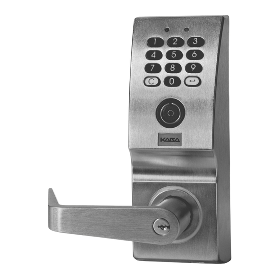
Introduction Lock Description The PowerLever ® Model 455x Door Lock is an advanced design electronic lock that operates using internally-generat- ed power, “PowerStarTM technology”, and includes a microprocessor. The outside cover assembly includes a keypad for entry of control data, a pair of LEDs (red and green) for visual feedback, a beeper for audio feedback, and the outside lever with a return of ⁄... -
Page 5: Additional Materials
Caution: When opening the lock, do not depress the outside lever to retract the bolt until the lock responds with three beeps/flashes of the green LED to indicate available entry. 3. The Passage Function is programmed to maintain the lock in the unlocked position. No combination is required to open the lock when it is in this state of operation. -
Page 6: Key User Lock Personnel Classifications
Key User Lock Personnel Classifications Only one lock personnel classification is defined within the Key User type: • Key Access User - A user, added by the Master User or a Manager User, who has the ability to open the lock using a Smart Key. -
Page 7: Combinations (Keypad Users)
Combinations (Keypad Users) For all keypad users, the PowerLever Model 455x Door Lock is accessed via a combination entered at the keypad. A Variable Length Combination is a feature of the Model 455x lock. The combination can consist of as little as a one- digit User ID or the length can be up to eight digits in length and consist of a User ID followed by a PIN. -
Page 8: Access Schedules
Access Schedules Note: This feature requires the PowerLever PC software to complete the operation. Each lock has six available access schedules (1-6) that can be defined by managerial personnel using the PowerLever PC program for Keypad User access to the lock. An access schedule is a period of time, or shift, during which users can open the lock. -
Page 9: Lock Responses
Lock Responses The tables below summarize how the red and green LEDs are flashed individually, simultaneously, or in combination to indicate various conditions. Each LED flash is accompanied by a beep for audio reinforcement. Flashes Green LED Red LED Continuous SA Key* Required at Reader Low Power Keystroke Entry... -
Page 10: Passage Function
Passage Function Programming the Passage Function will change the state from locked to unlocked of the PowerLever Door Lock. When programmed to the unlocked, or Passage function, no combination or key override is required for entry. Only managerial personnel are authorized to program the Passage Function. The factory default of a new lock is Passage Function = Off (Locked). -
Page 11: Retrieve User Information
Retrieve User Information Note: The Lock User Table contains information for Keypad Access Users, Key Access Users, Audit Users, and Service Users. When a Master User downloads the user table, information for Manager Users and the Master User is also included. The lock’s user information reporting feature lists the following for users of an activated lock: •... -
Page 12: Getting Started
Getting Started This section identifies lock setup activities and startup operations. Open Shelved Lock Using Default Combination The lock can be opened while in a Shelved state using the default Master User combination of all 0’s. Note: The lock is shipped pre-set from the factory with the default Master User combination of 00000000 (User ID=0000;... -
Page 13: Additional Lock Operations
Master User / Manager Users 1. Add Keypad Access User(s) (page 17) - or - Load Lock User Table Data (page 33) Key Access Users 1. Change PIN* (page 19) * If PIN length is not 0. 2. Open Lock (page 21) Keypad Access Users 1. -
Page 14: Lock Operations
Lock Operations Define Number of Key Access Users and Keypad User PIN Field Length Note: The lock must be in the Shelved mode to select this menu. Step Detailed Instructions Power lock. Power the lock by depressing the outside lever. Enter Master User Enter the Master User combination on the lock keypad. -
Page 15: Activate A Manager User
Step Detailed Instructions Press then 50. Before re-lock time expires, press (Enter key) followed by the 5 key and then the 0 key. The lock responds with two beeps/flashes of the green LED. Enter new Master User Enter the new Master User combination. The lock responds with two beeps/ combination. -
Page 16: Set Lock Time And Date
Set Lock Time and Date This feature enables managerial personnel to set the time and date in the lock. Note: Only the Master User and Manager Users can set the time and date in the lock. To set the lock time and date, complete the following steps: Step Detailed Instructions Power lock. -
Page 17: Add Keypad Access User(S)
Add Keypad Access User(s) Note: You do not need to perform this operation if you are downloading users from the PC. Note: If at any time during the procedure the lock power drops below a sufficient level for operation, the lock will continually beep and flash the red LED, prompting the user to depress the outside lever to provide additional power within 5 seconds. -
Page 18: Add Audit User(S)
Add Audit User(s) Note: As many Audit Users can be activated as there are available keypad user table spaces in the lock. Note: If at any time during the procedure the lock power drops below a sufficient level for operation, the lock will continually beep and flash the red LED, prompting the user to depress the outside lever to provide additional power. -
Page 19: Change Key Access User Pin
Step Detailed Instructions Press then 50. Before re-lock time expires, press (Enter key) followed by the 5 key and then the 0 key. The lock responds with two beeps/flashes of the green LED. Enter User’s new Enter the new Manager User or Keypad Access User combination (User ID combination. -
Page 20: Open The Lock With Combination
Step Detailed Instructions Press then 50. Before re-lock time expires, press (Enter key) followed by the 5 key and then the 0 key. The lock responds with two beeps/flashes of the green LED. Enter new Master User Enter a new Master User combination. The lock responds with two simulta- neous beeps/flashes of the green LED if the User ID portion of the combina- tion is unique. -
Page 21: Open The Lock With Access User Key
Open the Lock with Access User Key Step Detailed Instructions Power lock. Power the lock by depressing the outside lever. Insert Access User Key into Insert the Access User Key into the lock key reader. If the Access User Key key reader. -
Page 22: Remove Service User Combination
Step Detailed Instructions Enter new Service User Enter the Service User combination (1–8 digits depending on combination. the maximum number of Keypad Users allowed and the Keypad User PIN field length). The lock responds with two beeps/flashes of the green LED if the User ID portion of the combination is unique. -
Page 23: Determine Model Type
Determine Model Type This feature provides identification of the model type, i.e., Model 455x. To determine the model type, complete the fol- lowing steps: Step Detailed Instructions Power lock. Power the lock by depressing the outside lever. Enter Master User or a Enter the Master User or a Manager User combination. -
Page 24: Display Lock Enabled / Disabled Status
Display Lock Enabled / Disabled Status Step Detailed Instructions Power lock. Power the lock by depressing the outside lever. Enter Master User or a Enter the Master User or a Manager User combination. The lock will beep/ Manager User combination. flash the green LED on each keystroke entered. -
Page 25: Disable A Keypad User
Disable a Keypad User Note: This operation is used to disable lock access for either Keypad Access Users or Service Users. Step Detailed Instructions Power lock. Power the lock by depressing the outside lever. Enter Master User or a Enter the Master User or a Manager User combination. The lock will beep/ Manager User combination. -
Page 26: Disable A Key Access User
Step Detailed Instructions Repeat Steps 4–5 to enable If additional Key Access Users are to be enabled, repeat steps 4-5 until all more Key Access Users or User IDs have been enabled. If no additional Key Access Users are to be go to step 7. -
Page 27: Delete Key Access User(S) Using The Keypad
Step Detailed Instructions Press then 30. Before re-lock time expires, press (Enter key) followed by the 3 key and then the 0 key. The lock responds with two beeps/flashes of the green LED. Enter Keypad User ID. Enter a Keypad User ID to be deleted (or press the Enter key to exit.) The lock responds with two beeps/flashes of the green LED if the User ID is valid. -
Page 28: Delete Key Access User Using The Smart Key
Step Detailed Instructions Caution: If you are deleting multiple Key Access User IDs, you may need to depress the outside lever to provide additional power. Press Press (Enter key) to exit this procedure. The lock responds with two simultaneous beeps/flashes of the green and red LEDs and exits this procedure. -
Page 29: Change Keypad User Pin Field Length
Change Keypad User PIN Field Length Note: This operation may be performed while the lock is Activated. Step Detailed Instructions Power lock. Power the lock by depressing the outside lever. Enter Master User Enter the Master User combination. The lock will beep/flash the green LED on combination. -
Page 30: Retrieve Audit Records
Retrieve Audit Records On the Model 455x PowerLever Lock, audit records may be retrieved using either an SA Key or a Palm Organizer. Each audit transaction includes a date and time stamp. Only the most recent 1,022 audit records can be placed on the SA Key. -
Page 31: Retrieve User Information
Step Detailed Instructions Press then 6. (Audit Before re-lock time expires, press (Enter key) followed by the 6 key. (If Users press only.) an Audit User is retrieving audit records, press (Enter key) only.) The lock responds with one beep/flash of the green LED every second until the Palm interface cable has been inserted into the lock communication connector. -
Page 32: User Information Retrieval Via Sa Key
User Information Retrieval Via SA Key The process for retrieving User information is the same as that for retrieving audit information (The only difference is that the SA key has been initialized to retrieve User information rather than audit information). To retrieve information: Step Detailed Instructions Power lock. -
Page 33: Load Lock User Table, Holiday & Daylight Savings Time Data Created On Pc
Step Detailed Instructions lock serial number and data line number contained in the transaction will dis- play at the top of the report. All Access Users, Audit Users, Service Users, and Key Users will appear in the user table list. Master Users and Manager Users will not display unless the Master User is performing the user informa- tion retrieval. -
Page 34: Lock User Table, Holiday & Daylight Savings Time Data Upload Via Palm Organizer
Note: If at any time during the procedure the lock power drops below a sufficient level for operation, the lock will continually beep and flash the red LED, prompting the user to depress the outside lever to provide additional power. Step Detailed Instructions Ensure lock remains powered... -
Page 35: Display Daylight Savings Time Status
Display Daylight Savings Time Status This feature enables managerial personnel to display the Daylight Savings Time status in the lock. Note: Only the Master User and a Manager User can display Daylight Savings Time status in the lock. To display Daylight Savings Time status, complete the following steps: Step Detailed Instructions Power lock. -
Page 36: Quick Reference
Quick Reference Lock Keypad Commands The following is a list of the keypad commands that are available for the PowerLever 455x Series lock. Command Description and then 00 Retrieve Audit Records (p. 30) and then 01 Retrieve User Information (p. 31) and then 10 Set Re-Lock, Wrong Try Penalty Limit and Times (p. - Page 37 Notes...
- Page 38 Notes...
- Page 39 Notes...
- Page 40 Kaba Access Control 2941 Indiana Avenue Winston-Salem, NC 27105 USA Tel: 800.849.8324 336.725.1331 Fax: 800.346.9649 336.725.3269 438.030 0210 www.kabaaccess.com...
Need help?
Do you have a question about the PowerLever 455 Series and is the answer not in the manual?
Questions and answers