Advertisement
Advertisement

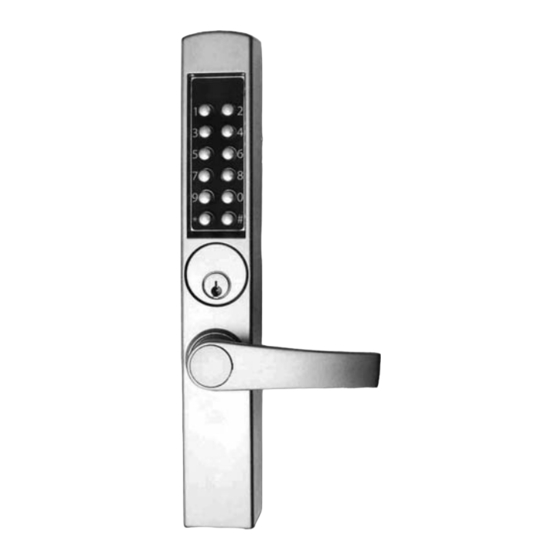
Summary of Contents for Kaba E-PLEX 3x65 Deadlatch/Exit Mortise
- Page 1 E-PLEX ® 00 SERIES NARROW STILE LOCK INSTALLATION INSTRUCTIONS...
-
Page 2: Table Of Contents
• (1) Outside Lever (Lever Model Only) • (1) Screw Pack • (1) Battery Housing with four AA Batteries (alkaline) • (2) Keys (Schlage C or Kaba 90 Keyway) • Documentation pack consists of: (1) Installation Instructions (this manual) (1) Operations Manual... -
Page 3: Tools Required
Disclaimer: While reasonable efforts were made to ensure the accuracy of this document at the time of printing, Kaba assumes no liability for any errors or omissions. This information is subject to be revised without notice, and changes... - Page 4 If a doorstop is required, we recommend the use of a floor secured stop. The environment and conditions of use determine the life of finishes on Kaba Access Control products. Finishes on Kaba Access Control products are subject to change due to wear and environmental corrosion.
-
Page 5: Stile Preparation
B. STILE PREPARATION B-1 Install the Kaba Cam Plug d1 or d2 into the Deadlatch or Deadbolt. Face of Cam Plug must be flush or below the surface of the stile, make sure set screw is snug but do not tighen it yet. (See Figure 2 on page 3). -
Page 6: Lock Preparation
C. LOCK PREPARATION On Deadlatch Model only, remove Handing Screw (FIG 4): Caution: The appropriate handing screw must be removed for proper lock function after installation. Inside the battery compartment, the lock comes with both handing screws installed. Based on the door application handing, Left Hand (LH) or Right Hand (RH) one screw must be removed as noted in FIG 4. - Page 9 Notes...
- Page 10 Notes...
- Page 11 C-3 Changing the Key Cylinder: A standard, factory installed cylinder (54450) has been provided with the E-Plex 3000. To change/replace the cylinder, carefully follow the steps below. 1. Change Master Code and place lock in Passage Mode. STEP 1. Enter # to Start the Programming Mode STEP 2.
- Page 12 Orient the lock to keep the Key Override Cam clear and insert the new cylinder (Fig 11). Allow gravity to assist in keeping the Key Override Cam out of the Figure 11 opening. Insert the new cylinder all the way until the MS Cam bottoms out on the Gear Pack.
-
Page 13: Lock Installation
D. LOCK INSTALLATION Figure 15a (See Figs. 15a, b, and c) Note: This step is to be done with the door open. D-1 From the Screw Pack, place the two Mounting Bushings (b) into the upper, interior ⁄ ” holes. D-2 Deadlatch: Place one end Deadlatch of the square spindle into... - Page 14 D-7 Locks with Levers–Based on the required handing of the lock as deter- mined in section C, install the Lever (h) and Lever Cap (g) using torx screws (f) and provided torx wrench. Secure lever cap (g) with Allen Set Screw using supplied Allen wrench.
-
Page 15: Standard Operations Procedures
E. STANDARD OPERATING PROCEDURES This lock is equipped with a standard break away clutch. In the “home position,” the lever or thumb turn is horizontal to the floor with the ability to “break away” down to a detented position as the lever or thumb turn is rotated. - Page 16 Kaba Access Control 2941 Indiana Avenue Winston-Salem, NC 27105 USA Tel: (800) 849-8324 (336) 725-1331 Fax: (800) 346-9640 (336) 725-3269 www.kabaaccess.com www.e-plexlock.com PKG3215 1107...


Need help?
Do you have a question about the E-PLEX 3x65 Deadlatch/Exit Mortise and is the answer not in the manual?
Questions and answers