Table of Contents
Advertisement
Advertisement
Table of Contents

Related Manuals for Kaba E-Plex 5x00 Cylindrical


Summary of Contents for Kaba E-Plex 5x00 Cylindrical
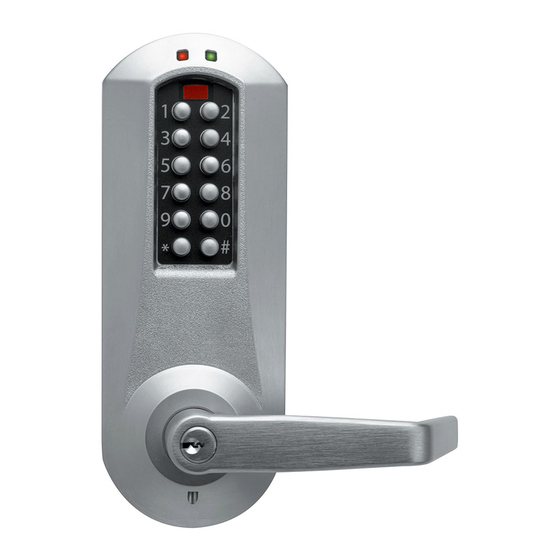
- Page 1 Installation Instructions 5 x 0 0 C y l i n d r i c a l...
-
Page 2: Table Of Contents
• Small flat blade screwdriver Warnings and Cautions Important: Carefully inspect windows, doorframe, door, lights, etc. to ensure that the recommended procedures will not cause damage. Kaba Access Control’s warranty does not cover damages caused by installa- tion. For technical assistance please call Caution: Wear safety glasses when preparing door. -
Page 3: Door Preparation
A. DOOR PREPARATION B. LOCK HANDING A-1 Place paper template (supplied) onto door and The E-Plex 5000 is a non-handed lock that is preassembled for left-hand mark for holes. Drill the four ⁄ " (7 mm) holes first. door installations. Next drill the 2 ⁄... -
Page 4: Installing Outside Unit Assembly
Note: Installing levers to the unit assemblies before mounting E-3 Insert LectroBolt through the red inside the unit assemblies may ease initial installation. housing hole marked with the lightening LectroBolt bolt symbol. here LectroBolt D. INSTALLING OUTSIDE UNIT ASSEMBLY screw D-1 Slide the drive unit (a) into 2 ⁄... - Page 5 5x00 SERIES LIMITED WARRANTY Kaba Access Control warrants this product to be free from defects in material and workmanship under normal use and service for a period of three (3) years. Kaba Access Control will repair or replace, at our discretion, 5000 Series Locks found by Kaba Access Control analysis to be defective during this period.
- Page 6 Notes...
-
Page 7: Changing Key-In-Lever/Knob (Kil/Kik) Cylinder
45 degrees to the horizontal position. Remove key. Marks G-2 Determine the proper tailpiece from the chart above for your KIL/KIK cylinder. You must use a Kaba tailpiece. The K 2 tailpiece is preassembled with the Kaba 1599. -
Page 8: Installing / Removing Outside Lever/Knob
Note: To remove the outside lever/knob from Insert the supplied tailpiece (e) vertically into the the outside unit assembly, follow step below. outside lever/knob (b) as shown. Make certain that you rotate the tailpiece so it will align with the inter- H-4 Insert one of the (supplied) keys (a) into changeable core. -
Page 9: Installing The Battery Pack And Cover/Changing Batteries
J. INSTALLING THE BATTERY PACK AND COVER / K. TESTING THE OPERATION OF THE LOCK K-1 Rotate inside lever/knob and hold. Ensure that the latch is fully retracted CHANGING BATTERIES and flush with the latch faceplate. Release the inside lever/knob; the latch J-1 To install the battery pack (f) and cover should be fully extended. -
Page 10: Installing Strike
Note: For security reasons, all existing audit events are not deleted. Caution: Check the operation of the latch by The lock is now set to the factory-configured setup with the default factory making sure that the deadlatch (a) stops master code, 1,2,3,4,5,6,7,8. Important: Before you can program the lock against the strike (b) as shown and does not you must first enter a new 8 digit master code of your choice. - Page 11 Kaba Access Control 2941 Indiana Avenue Winston-Salem, NC 27105 USA Tel: (800) 849-8324 (336) 725-1331 Fax: (800) 346-9640 (336) 725-3269 PKG2992 1206 www.kabaaccess.com www.e-plexlock.com...
Need help?
Do you have a question about the E-Plex 5x00 Cylindrical and is the answer not in the manual?
Questions and answers