Table of Contents
Advertisement
Advertisement
Table of Contents

Subscribe to Our Youtube Channel
Related Manuals for Kaba E-PLEX


Summary of Contents for Kaba E-PLEX
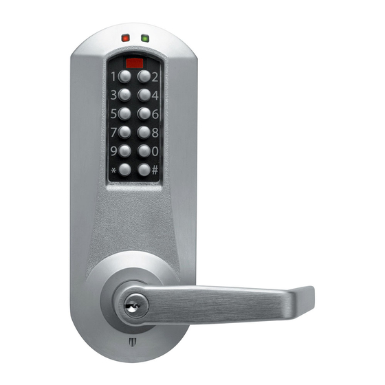
- Page 1 ® E PLEX ” MORTISE INSTALLATION INSTRUCTIONS...
-
Page 2: Table Of Contents
Warnings and Cautions Important: Carefully inspect windows, door frame, door, lights, etc. to ensure that the recommended procedures will not cause damage. Kaba Access Control’s warranty does not cover damages caused by installation. Caution: Wear safety glasses when preparing door. -
Page 3: Tools Required
For models without deadbolts, please disregard any references to a thumbturn in the instructions. OPERATIONAL NOTE: The E-Plex Mortise lock is almost identical to the E-Plex 5000 Cylindrical lock with the following exceptions: 1. Operation of the Lever When the lock’s handing is properly set, only a downward rotation of lever will actuate latch. -
Page 4: Exploded Install Parts
Assembly Mortise Faceplate The 1 ⁄ " Mortise lock for the E-Plex series comes preassembled from the factory for a left-hand installation. It is field reversible. Installation Qualifications These instructions are designed for use by maintenance professionals or lock installers who are familiar with common safety practices and competent to perform the steps described. -
Page 5: Mortise Handing
A. MORTISE HANDING For LH (left hand) and For RH (right hand) and RHR (right hand reverse) LHR (left hand reverse) Compare the mortise with the figure. If the mortise is the correct handing for the door, you may skip the next section on reversing the Mortise Handing. A. - Page 6 Unlock Position Lock Position A-1.1 Continued 3. Push in the latch bolt (L) to the middle of its stroke, and hold it there. (Continue Step 1 and 2) Hold the latch (L) inside the mortise, and insert the tail- piece retaining tool (S) so that the tailpiece (T) will not drop inside the mortise case.
- Page 7 Release the latch to the middle of the stroke and hold it there. Use a small screwdriver to push the lock mechanism back on lock position (see step 1 and 2). IMPORTANT: The lock mechanism has to be horizontal on lock position. F (tooth) 5.
-
Page 8: Door Preparation
The mortise should look like the diagram at the right. (Check the orientation of the latch bolt and auxiliary latch.) Check the bevel of the mortise and change it if required as described in section B-8 on page 14. For LH (left hand) and RHR (right hand reverse) For RH (right hand) and LHR (left hand reverse) - Page 9 The axis of rotation of the handle is level with the bottom lip of the strike. B-2 Align the template along the vertical center line of the mortise (CL) at the desired handle height, and tape it to the door. B-3 Mark all holes and cutouts for the mortise in the edge of the door and Mortise...
- Page 10 5x00 SERIES LIMITED WARRANTY Kaba Access Control warrants this product to be free from defects in material and workmanship under normal use and service for a period of three (3) years. Kaba Access Control will repair or replace, at our discretion, 5000 Series Locks found by Kaba Access Control analysis to be defective during this period.
- Page 13 Notes...
-
Page 14: Installing The Strike
B-8 Check the bevel of the mortise faceplate. If adjustment is required, loosen the two bevel screws and adjust mortise front plate angle to match the bevel of the door (R). B-9 Re-tighten screws. B-10 Install the mortise with two 1" Phillips screws (Q) provided. B-11 Install mortise faceplate (P) with the two 8-32 x ⁄... -
Page 15: Installing Outside Unit Assembly
C-4 Position the strike against the door frame and align it with the mounting screw holes. Then mark the outline of the strike. C-5 Remove any material from within the strike outline (a) so that the strike will be flush with the door frame. -
Page 16: Installing The Inside Lever
E-2 For door thickness of 1 ⁄ " – 2", insert the short Red Collar square spindle (G) into the inside housing hub. Door thickness of 2 ⁄ " – 2 ⁄ ", insert the long square spindle into the inside unit hub. E-3 Put the thumbturn (T), if applicable in a vertical position and place the inside trim assembly on the door so that the upper spindle (F) engages... -
Page 17: Changing Key-In-Lever Cylinder
G. CHANGING KEY-IN-LEVER CYLINDER On key-in-lever models of the E-Plex 5000 series, the outside lever comes preassembled with Kaba’s key-in-lever cylinder (Kaba 1599). To use a different key-in-lever cylinder follow remaining steps in this section. G-1 To remove KIL (key-in-lever) cylinder (a) from the outside lever (b). -
Page 18: Installing / Removing Outside Lever (Key-In-Lever) Kil
H. INSTALLING / REMOVING OUTSIDE LEVER (Key-In-Lever models only) H-1 Make certain the lever catch is up as shown (c). To successfully install the outside lever, the lever sleeve (f) tab must be positioned correctly with the respective notch on the lever. The lock comes shipped with the lever sleeve already installed in the Incorrect Correct... - Page 19 I-2 Insert the outside lever (a) until it is flush to the outside unit assembly (b). To secure the outside lever, insert the release tool (d) (or screwdriver) into the outside lever as shown, and slide the lever catch down until it clicks. Make certain lever is attached before installing the core.
-
Page 20: Installing The Battery Pack And Cover
I-10 Insert the lever release tool (d) into the small hole (f) under lever as shown. Gently push lever catch up until it clicks. Remove tool, then remove outside lever (a). Note: You may want to use needle nose pliers for some tailpieces. Insert the release tool (d) into the small hole (f) under the lever as shown. -
Page 21: Testing The Operation Of The Lock
You must change the master Code from the factory default to another code to program the lock. For further information on how to manually program the E-Plex 3x00/5x00 Series Models, refer to the companion “E- Plex 3x00/5x00 Operation Manual.” Software is required to program the E3200/E5200 Series Locks. -
Page 22: Installing Rubber Bumpers
M. INSTALLING RUBBER BUMPERS M-1 Close the door and apply pressure making sure the deadlatch (a) rests on the strike plate (b) as shown. Standing on the frame (door step) side of the door, check for gaps between the door and the frame on the three sides of the frame (left, right and top). - Page 23 Notes...
- Page 24 Kaba Access Control 2941 Indiana Avenue Winston-Salem, NC 27105 USA Tel: (800) 849-8324 (336) 725-1331 Fax: (800) 346-9640 (336) 725-3269 www.kabaaccess.com PKG3090 0912...
Need help?
Do you have a question about the E-PLEX and is the answer not in the manual?
Questions and answers