Table of Contents
Advertisement
Quick Links
Advertisement
Table of Contents

Related Manuals for Kaba PowerLever 1550


Summary of Contents for Kaba PowerLever 1550
- Page 1 Door Lock Series ™ NSTALLATION UIDE Models 1550, 4550/4560, PROX 9000...
- Page 2 NOTICE: The information in this manual is subject to change without notice and does not represent a commitment on the part of Kaba Ilco. Kaba Ilco shall not be liable for technical or editorial errors or omissions contained herein; nor for incidental or consequential damages resulting from the furnishing, performance or use of this material.
-
Page 3: Table Of Contents
ABLE OF ONTENTS ..........................1 NTRODUCTION Lock Description ..........................1 Self-Power Operation ......................... 1 Door Handing ............................. 2 Basic Tools and Materials Needed ..................... 2 ..........................3 ARTS HECK Illustrated Parts Breakdown ....................... 3 ......................... 6 NSTALLATION EMPLATE ........................7 REPARATION Mark the Door ............................ - Page 4 ..........................22 PECIFICATIONS Electronic Specifications ........................22 Hardware Specifications ........................22 ......................... 22 ROUBLESHOOTING...
-
Page 5: Introduction
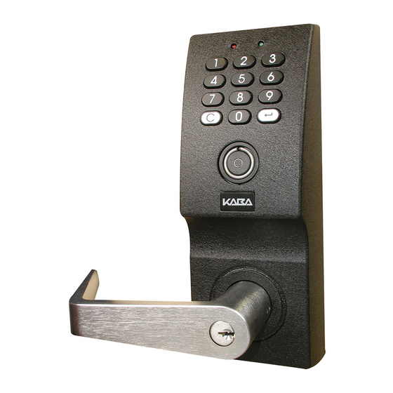
Door Lock is an advanced design electronic lock that operates using inter- nally-generated power, “PowerStar technology”, and includes a microprocessor and a cylindri- cal lock mechanism. Installation of the following lock models is covered in this manual: · PowerLever 1550 · PowerLever 4550/4560 · PowerLever PROX 9000 Note: Various lock models will be shown throughout the Installation Guide. -
Page 6: Door Handing
Door Handing The PowerLever Door Lock can be installed as Right Hand Reverse or Left Hand Reverse. Basic Tools and Materials Needed Before beginning installation, be certain that you have the following tools readily available: • Measuring tape • Combination square •... -
Page 7: Parts Check
ARTS HECK Illustrated Parts Breakdown Figure 1 Document Number 481.093 Rev. A - 06/04 Parts Check... - Page 8 Item Description Screw packet for latchbolt assembly and strikes containing: • 2 - #8 x 3/4” Phillips head combination screws • 2 - #8 x 3/4” Phillips head combination screws • 2 - #12 x 3/4” Phillips head combination screws Trim mounting packet for 1 3/8”...
- Page 9 Item Description Chassis assembly for levers using conventional (non-interchangeable) key cylinder Chassis assembly for levers using interchangeable key core Inside case assembly Inside backing plate/Electronics assembly - Model 1550 Inside backing plate/Electronics assembly - Model 45xx Inside backing plate/Electronics assembly - Model 9000 Latchbolt assemblies •...
-
Page 10: Installation Template
NSTALLATION EMPLATE Caution: The following installation template is not to scale and is meant to be used for refer- ence only. It is not meant to be used for actual installation of the lock. INSTALLATION TEMPLATE PowerLever ® NOT TO SCALE Door Lock Series P/N 482.093... -
Page 11: Door Preparation
REPARATION Mark the Door Note: Accurate door preparation, including drilling throughbolt holes, is essential for proper operation. The hand and bevel of the door affect template use. For doors already prepped, make sure the preparation correctly matches the templates provided before drilling throughbolt holes. -
Page 12: For All Doors
For all doors: 6. Locate and mark the center for the four 11/32” (8.7mm) diameter throughbolt clearance holes. Refer to Figure 4. 7. Locate and mark the center for the 1” (25.4mm) diameter thru-hole for the system cable. 8. Center punch all hole positions onto the door. -
Page 13: For All Doors
4. Using the pilot hole, drill a 1” (25.4mm) diameter hole for the latchbolt into the edge of the door. Make sure the latchbolt hole is level and perpendicular to the 2 1/8” (54mm) diameter hole. 5. Mortise the edge of the door 1 1/8” x 2 1/4” x 5/32” (29mm x 57mm x 4mm) for the latch front. For all doors: 1. -
Page 14: Installation
NSTALLATION Install the Latchbolt 1. Check the door swing and orient the latchbolt to the hand of the door. Refer to Figure 7. 2. Insert the latchbolt into the hole in the door as shown in Figure 7. Using the latchbolt front as a tem- plate, centerpunch and drill two (2) 1/8”... -
Page 15: Install The Lock Chassis/Outside Case Assembly
Install the Lock Chassis/Outside Case Assembly If you are installing a Model 45xx lock or a PowerLever PROX Communication System 9000 lock, the outside case assembly includes a communication Cable Cable cable that exits the outside case assembly at the same location as the system cable (as shown in the photo.) The communication cable is a 6-conductor ribbon cable that carries communication signals from the RJ-12 connector on the outside case assembly... -
Page 16: Install The Inside Backing Plate/Electronics Assembly
3. From the outside of the door, feed the solenoid cable through the 2 1/8” (54mm) hole. Caution: Ensure that the solenoid cable does not get tangled in the latchbolt mechanism. 4. From the outside of the door, feed the system cable and communication cable (if applicable) through the 1”... - Page 17 4. Refer to Figure 14. Install the two top 1/4-28 x 2 1/2” Phillips round head screws with the appropriate spac- ers to compensate for the door thickness, and with the lockwashers (Refer to note below). Do not tighten yet. Note:Use the two 7/16”...
-
Page 18: Install The Cables
Install the Cables Warning: Do not remove the shield. This could cause damage to the system card. Warning: Ensure that the solenoid cable is routed to the inside of the PEM nuts used for mounting the inside case. The solenoid cable will exit either the left or right hole in the backing plate depend- ing on the latchbolt position. -
Page 19: Install The Inside Case
Install the Inside Case Note: Refer to Figure 16. 1. Slightly wiggle and push the inside case assembly over the lock cylinder assembly, past the lever catch and against the door. Note: Ensure that the solenoid cable is not pinched and is routed through the cable clip. -
Page 20: Attach The Outside Lever
Attach the Outside Lever Conventional (Non-Interchangeable) Key Cylinder 1. Refer to Figure 18. Make sure the cylinder tailpiece is aligned in the same direction as the cylinder bible. Slide the cylinder all the way into the lever. 2. Select the appropriate cylinder insert. Refer to Figure 19. -
Page 21: Tailpieces
Part Number Diagram Cylinder Application 405458 Kaba Ilco 404078 Ilco® 705, Kaba 1539, ASSA® 65691, Abloy® 5477, Arrow™ 100C. Packed 10 per and contains part number 405350. 404079 Schlage™ 23-001, Schlage Primus™, ASSA 65611, Corbin Russwin® Key-in-lever. Packed 10 per and contains part number 405351. -
Page 22: Interchangeable Key Core
Interchangeable Key Core Note: Refer to Figure 21. 1. Push the outside lever onto the lock tube. Slightly wiggle and push the lever until the lever engages with the lever catch. 2. If the door thickness is greater than 1 1/2” (38mm), the lever installation is complete. -
Page 23: Install The Interchangeable Key Core
Install the Interchangeable Key Core Note: Two (2) tailpieces for the interchangeable core are included with the lock: one for door thickness 1 1/2” (38.1mm) or less, and one for door thickness greater than 1 1/2” (38.1mm) . The interchangeable core is not included with the lock. -
Page 24: Test Procedure
Test Procedure After you have completed the installation of the lock, but prior to closing the door, you should perform the following test procedures to ensure that the lock is functioning properly. 1. Power the lock by depressing the outside lever. The lock should respond with one simulta- neous flash of the green and red LEDs accompanied by a beep to indicate that the lock is powered. -
Page 25: Service
ERVICE Remove the Outside Lever Conventional (Non-Interchangeable) Key Cylinder Note: Refer to Figure 25. 1. Insert the key and turn the key in the cylinder 45 degrees clockwise. 2. Push the lever release tool into the hole in the lever to depress the lever catch. - Page 26 PECIFICATIONS Electronic Specifications Power Unit: Solenoid Power: Self power by pressing outside lever Hardware Specifications Dimensions: Outside case: 3 1/2” x 9 1/4” x 2 3/8” (89mm x 235mm x 60mm); Inside case: 3 1/2” x 9 3/4” x 1 3/4” (89mm x 248mm x 44mm) Cover Material: Cast zamak Handing: Non-handed...
- Page 27 ROUBLESHOOTING Problem Solution Lever pulls off. Lever catch not fully engaged. Lock is not centered on door. Door too thick. Readjust the lockset for the door thickness. Refer to Step 1 under the “Adjust the Lockset for the Door Thickness” heading on page 10. Unable to assemble outside lever.
- Page 28 Document Number 481.093 Rev. A - 06/04...
- Page 29 OTES...
- Page 32 Document Number 481.093 Rev. A - 06/04 Kaba Access Control 2941 Indiana Avenue Winston-Salem, NC 27105 USA Tel: (800) 849-8324 (336) 725-1331 FAX: (800) 346-9640 (336) 725-3269 Technical Support: (800) 950-4744 www.kaba-ilco.com www.powerleverprox.com...
Need help?
Do you have a question about the PowerLever 1550 and is the answer not in the manual?
Questions and answers