Table of Contents
Advertisement
Advertisement
Table of Contents

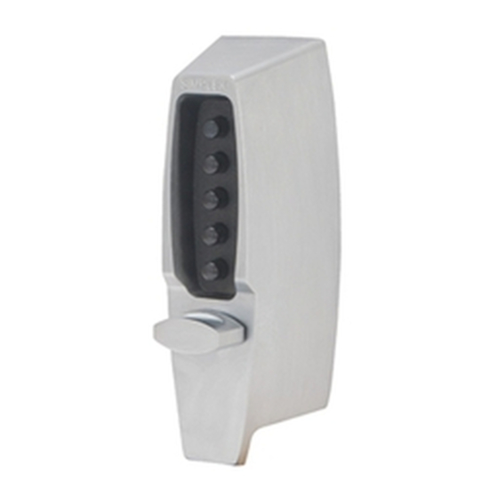
Summary of Contents for Kaba 7102 series
- Page 1 Installation Instructions 7 1 0 2 7 1 0 8 SERIES...
- Page 2 PLEASE READ AND FOLLOW ALL DIRECTIONS CAREFULLY Since every installation is unique, carefully check windows, frame, door, etc. to ensure that the recommended procedures will not cause damage. KABA is not responsible for any damage caused by installation. Tools Required •...
-
Page 3: Table Of Contents
Table of Contents Checklist ..............2 Determining the Hand of Your Door . -
Page 4: Checklist
CHECKLIST Use this checklist to make sure that everything has been included. A - Front Lock C - Dead Bolt 7102 (2 ⁄ ") or 7108 (2 ⁄ ") (model specific) D - Inside Thumbturn Assembly E - Inside Combination Change Assembly Screw Pack: F - Strike Plate G - 4 thru-bolts (3") -
Page 5: Determining The Lock Location
A. DETERMINING THE LOCK 4" (102 mm) LOCATION Install the lock with the exterior thumbturn hole at least 7" (18 cm) above your primary lockset so it is comfortable to operate and not in the way when you turn the door knob. A minimum stile width of 4"... -
Page 6: Making The Bolt Face Plate Cutout
C-2 Use a hole saw with pilot bit to make the 1 ⁄ " ⁄ " (41 mm) hole (B). Apply pressure evenly until the circular blade cuts the first side of the door and the tip of the pilot bit emerges through the other side, then stop. -
Page 7: Adjusting The Lock
E-2 Left Hand Door (see template) a. Insert the bolt, with the arrow pointing down, into the 1" (25 mm) hole (See Figure 5-2). b. Secure the bolt face plate to the door with the two Phillips-head screws provided. F. ADJUSTING THE LOCK The lock has been pre-assembled to accommodate doors up to 2 ⁄... -
Page 8: Installing The Lock
G. INSTALLING THE LOCK • For 1 ⁄ " - 1 ⁄ " (35 mm - 38 mm) thick doors, use the 2 ⁄ " (44 mm) thru bolts. • For 1 ⁄ " - 2" (38 mm - 51 mm) thick doors, use the 2 ⁄... -
Page 9: Checking The Locks Operation
H. CHECKING THE LOCK’S OPERATION IMPORTANT: The following steps MUST be performed while the DOOR IS OPEN. Note: Turning the outside thumbturn to the left (counterclockwise) to the stop position and releasing extends the bolt to the locked position. To retract the bolt from the outside, depress the buttons of your preset combination, then turn the thumbturn to the right (clockwise) to the stop position. - Page 10 Kaba Access Control analysis to be defective during this period. Our only liabil- ity, whether in tort or in contract, under this warranty is to repair or replace products that are returned to Kaba Access Control within the one (1) year war- ranty period.
- Page 11 CAUTION Apply template and drill from the outside but compensate for door bevel if any *backset NOTE: Lock will accomodate doors " (35 mm) to 2 " (57 mm) thick. Suitable reinforcement shall be provided by the hollow metal door manufacturer to prevent collapsing of door.
- Page 12 CAUTION Apply template and drill from the outside but compensate for door bevel if any *backset NOTE: Lock will accomodate doors " (35 mm) to 2 " (57 mm) thick. Suitable reinforcement shall be provided by the hollow metal door manufacturer to prevent collapsing of door.
- Page 13 " dia. (19 mm) " dia.* " dia.* (6 mm) (6 mm) IMPORTANT Drill the four " (6 mm) dia. holes " before all other holes. (32 mm) " " (95 mm) (60 mm) *BACKSET " For door with existing 2 "...
- Page 14 " dia. (19 mm) " dia.* " dia.* (6 mm) (6 mm) IMPORTANT " (32 mm) Drill the four " " (6 mm) dia. holes (95 mm) before all other holes. " (60 mm) *BACKSET For door with existing 2 "...
- Page 17 Notes...
-
Page 18: Installing The Strike
Verify the Combination Change Assembly H-8 Insert the tip of a Phillips-head screwdriver into the combination change assembly B (See Figure 8-5). H-9 Turn the central piece to the right (clockwise) until it stops, DO NOT FORCE, (approximately 30˚ degrees) (See Figure 8-5). H-10 Remove the screwdriver;... - Page 19 J-2 Enter the existing code (See Figure 10-2). J-3 Insert a Phillips-head screwdriver into the cen- ter of the combination change sleeve. Gently turn to the right (clockwise) approximately ⁄ " (3 mm) (See Figure 10-3). A slight click should be felt.
-
Page 20: Instructions For Resetting Unknown Combinations
Remove the combination chamber, held by 2 screws, from the lock. To remove the 3-sided dust cover marked "Kaba Simplex," place the combination chamber in the position below. - Page 21 K-13 Look at the code gear pockets (f). The numbers in you new combination should not be at the shear line (open position) (See Figure 11-3). Reinstallation: Replace the 3-sided dust cover marked “Kaba Simplex.” Make sure the staked joints on both end plates fit through the slots on the dust cover.
-
Page 22: Troubleshooting
L. TROUBLESHOOTING Lock fails to open when combination is entered and outside thumbturn is rotated clockwise. Buttons were not fully depressed when the combination was entered. Lock not cleared of previous attempts to enter access codes. Turn the outside thumbturn to the left to clear the wrong entry. Enter the combination making sure you feel each button click to know that it was depressed fully. - Page 23 Notes...
- Page 24 Kaba Access Control 2941 Indiana Avenue Winston-Salem, NC 27105 USA Tel: (800) 849-8324 (336) 725-1331 Fax: (800) 346-9640 (336) 725-3269 www.kabaaccess.com PK 2387 0307...


Need help?
Do you have a question about the 7102 series and is the answer not in the manual?
Questions and answers