
Related Manuals for Nexcom Neu-X102


Summary of Contents for Nexcom Neu-X102
- Page 1 NEXCOM International Co., Ltd. Intelligent Platform & Services Business Unit Edge Computing System Neu-X102 User Manual NEXCOM International Co., Ltd. www.nexcom.com Published November 2023...
-
Page 2: Table Of Contents
Hardware Specifications ................2 DC Power Input Jack ..............15 Physical Features ..................4 Debug Port Connector ..............15 Front Panel ..................4 GPIO Connector ................16 Rear Panel ...................4 LVDS Inverter Connector ..............16 Copyright © 2023 NEXCOM International Co., Ltd. All Rights Reserved. Neu-X102 User Manual... - Page 3 When to Configure the BIOS ..............31 Default Configuration ................32 Entering Setup ..................32 Legends ....................32 BIOS Setup Utility ..................34 Main ....................34 Advanced ..................35 Security .....................44 Boot ....................45 Save & Exit ..................46 Copyright © 2023 NEXCOM International Co., Ltd. All Rights Reserved. Neu-X102 User Manual...
-
Page 4: Preface
No describes how to keep the system CE compliant. part of this manual may be reproduced, copied, translated or transmitted in any form or by any means without the prior written consent from NEXCOM Declaration of Conformity International Co., Ltd. -
Page 5: Rohs Compliance
(Cr6+) < 0.1% or 1,000ppm, Polybrominated biphenyls (PBB) < 0.1% or 1,000ppm, and Polybrominated diphenyl Ethers (PBDE) < 0.1% or 1,000ppm. In order to meet the RoHS compliant directives, NEXCOM has established an engineering and manufacturing task force to implement the introduction of green products. -
Page 6: Warranty And Rma
“NEXCOM RMA Service Form” for the RMA number apply process. ▪ If RMA goods can not be repaired, NEXCOM will return it to the customer without any charge. ▪ Customers can send back the faulty products with or without accessories (manuals, cable, etc.) and any components from the card, such as CPU... - Page 7 ESD workstation. If no such station is available, you can provide some ESD protection by wearing an antistatic wrist strap and attaching it to a metal part of the computer chassis. Copyright © 2023 NEXCOM International Co., Ltd. All Rights Reserved. Neu-X102 User Manual...
-
Page 8: Safety Information
There is a danger of explosion if battery is incorrectly replaced. Replace only with the same or equivalent type recommended by the manufacturer. Discard used batteries according to the manufacturer’s instructions. viii Copyright © 2023 NEXCOM International Co., Ltd. All Rights Reserved. Neu-X102 User Manual... -
Page 9: Safety Precautions
UL/IEC 60950-1 and/or UL/IEC 62368-1. If further assistance is needed, please contact NEXCOM International Co., Ltd. (UL file owner or brand owner) for further information. Copyright © 2023 NEXCOM International Co., Ltd. All Rights Reserved. -
Page 10: Technical Support And Assistance
Preface Technical Support and Assistance Conventions Used in this Manual 1. For the most updated information of NEXCOM products, visit NEXCOM’s Warning: website at www.nexcom.com. Information about certain situations, which if not observed, can cause personal injury. This will prevent injury to yourself 2. -
Page 11: Global Service Contact Information
16F, No.250, Sec. 2, Chongde Rd., Tel: +886-2-8976-3077 Tel: +886-2-8226-7786 Beitun District, Email: sales@diviotec.com Fax: +886-2-8226-7782 Taichung City, 406, Taiwan, R.O.C. www.diviotec.com Email: services@tmrtek.com Tel: +886-4-2249-1179 www.tmrtek.com Fax: +886-4-2249-1172 Email: jacobhuang@nexaiot.com www.nexaiot.com Copyright © 2023 NEXCOM International Co., Ltd. All Rights Reserved. Neu-X102 User Manual... - Page 12 GanKeng Community, Buji Street, 4-11-5, Shiba Minato-ku, LongGang District, Tokyo, 108-0014, Japan ShenZhen, 518112, China Tel: +81-3-5419-7830 Tel: +86-755-8364-7768 Fax: +81-3-5419-7832 Fax: +86-755-8364-7738 Email: sales@nexcom-jp.com Email: steveyang@nexcom.com.tw www.nexcom-jp.com www.nexcom.cn Copyright © 2023 NEXCOM International Co., Ltd. All Rights Reserved. Neu-X102 User Manual...
-
Page 13: Package Contents
Flat Head Screw Long Fei: 2x4 Nylok NIGP F2x4 NIGP Nylok 50311F0330X00 Screw for mPCIe ROUND HEAD SCREW LONG FEI:P2x3 ISO+NYLON P2x3 NI NYLOK 7400060068X00 Power Adapter Power Adapter for NDiS B116 EDAC:EA10681N(T42) xiii Copyright © 2023 NEXCOM International Co., Ltd. All Rights Reserved. Neu-X102 User Manual... -
Page 14: Ordering Information
The following below provides ordering information for Neu-X102. Neu-X101-N50 (P/N: 10W10X10200X0) Intel Alder Lake-N processor, N50, slim and fanless system ® Neu-X102-N97 (P/N: 10W10X10201X0) Intel ® Alder Lake-N processor, N97, slim and fanless system Copyright © 2023 NEXCOM International Co., Ltd. All Rights Reserved. Neu-X102 User Manual... -
Page 15: Chapter 1: Product Introduction
▪ 1 x M.2 2242 Key M for supporting PCIe & SATA storage device ▪ Mini-PCIe slot supports Wi-Fi 6/6E and LTE module ▪ Support Power Input 12V DC Neu-X102-N97 Copyright © 2023 NEXCOM International Co., Ltd. All Rights Reserved. Neu-X102 User Manual... -
Page 16: Hardware Specifications
▪ 1 x Line-out audio connector ▪ FCC Class A (EMI Part 15B) ▪ 2 x (1 x 6P) Headers, for 3x USB 2.0 port ▪ LVD (EN62368-1) Copyright © 2023 NEXCOM International Co., Ltd. All Rights Reserved. Neu-X102 User Manual... - Page 17 Chapter 1: Product Introduction Dimensions ▪ Neu-X102-N50: 179.5mm (W) x 106mm (D) x 37mm (H) (with mount bracket) ▪ Neu-X102-N97: 203.5mm (W) x 106mm (D) x 40mm (H) (with mount bracket) Operating System ▪ Windows 10 64-bit, Windows 11 ▪ Linux 4.1 above Copyright ©...
-
Page 18: Physical Features
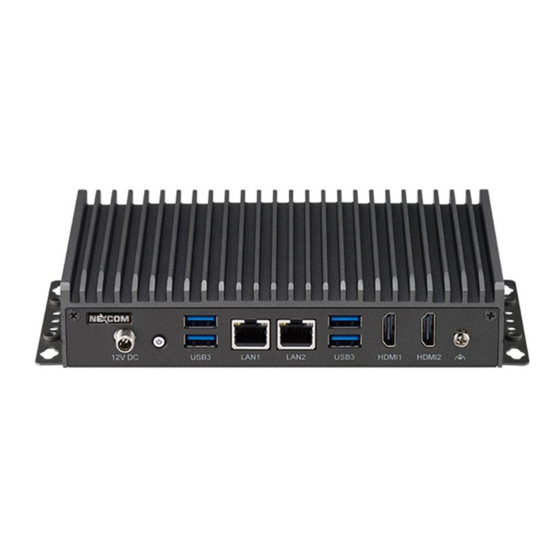
Chapter 1: Product Introduction Physical Features Front Panel Rear Panel Power Button Antenna Hole USB 3.2 LAN1 LAN2 USB 3.2 Antenna Hole Storage LED 12V DC Input HDMI1 HDMI2 Copyright © 2023 NEXCOM International Co., Ltd. All Rights Reserved. Neu-X102 User Manual... -
Page 19: Mechanical Dimensions
Chapter 1: Product Introduction Mechanical Dimensions Neu-X102-N50 179.5 169.0 155.0 #6-32_NUT Copyright © 2023 NEXCOM International Co., Ltd. All Rights Reserved. Neu-X102 User Manual... -
Page 20: Neu-X102-N97
Chapter 1: Product Introduction Neu-X102-N97 203.50 #6-32_NUT Copyright © 2023 NEXCOM International Co., Ltd. All Rights Reserved. Neu-X102 User Manual... -
Page 21: Chapter 2: Jumpers And Connectors
2: J haPter umPers and onneCtors This chapter lists the locations of the jumpers and connectors for Neu-X102. Before You Begin Precautions ▪ Ensure you have a stable, clean working environment. Dust and dirt can Computer components and electronic circuit boards can be damaged by get into components and cause a malfunction. -
Page 22: Jumper Settings
Refer to the illustrations below for examples of what the 2-pin and 3-pin jumpers look like when they are short (on) and open (off). Two-Pin Jumpers: Open (Left) and Short (Right) Three-Pin Jumpers: Pins 1 and 2 are Short Copyright © 2023 NEXCOM International Co., Ltd. All Rights Reserved. Neu-X102 User Manual... -
Page 23: Locations Of The Jumpers And Connectors
Locations of the Jumpers and Connectors The figures on this page and the next page show the top and bottom views of the mainboard used in Neu-X102, with the locations of jumpers and connectors. Refer to this chapter for detailed pin settings and definitions of the pink connectors on these two figures. -
Page 24: Bottom View
Chapter 2: Jumpers and Connectors Bottom View DIMM1 Copyright © 2023 NEXCOM International Co., Ltd. All Rights Reserved. Neu-X102 User Manual... -
Page 25: Jumpers & Dip Switches
Connector type: 1x3-pin header, 2.0mm pitch Connector location: CLRCMOS Connector location: LCD_PWR Settings Settings 1-2 On Normal (Default) 1-2 On 3.3V (Default) 2-3 On Clear CMOS 2-3 On Copyright © 2023 NEXCOM International Co., Ltd. All Rights Reserved. Neu-X102 User Manual... -
Page 26: Com2 Ri Select
Connector location: JP1 Connector location: SW1 Settings SW [3:0] SW1 [3] SW1 [2] SW1 [1] SW1 [0] RI (Default) 1111 1920 1080 COM2_RI (Default) Default: All OFF COM2_RI +12V Copyright © 2023 NEXCOM International Co., Ltd. All Rights Reserved. Neu-X102 User Manual... -
Page 27: Connector Pin Definitions
Connector type: 1x 2-pin header, 1.25mm pitch Connector type: WtoB, 1x 9-pin header, 1.0mm pitch, support RS232/422/485 Connector location: BAT Connector location: COM1 Definition RS232 RS422 RS485 Definition Definition Definition Copyright © 2023 NEXCOM International Co., Ltd. All Rights Reserved. Neu-X102 User Manual... -
Page 28: Com 2 Port Header
Connector type: WtoB, 1x 9-pin header, 1.0mm pitch, support RS232 only Connector type: WtoB Conn. 1x 4-pin header, 2.54mm pitch Connector location: COM2 Connector location: CPU_FAN Definition Definition Definition +12V FAN Speed Detect FAN Speed Control Copyright © 2023 NEXCOM International Co., Ltd. All Rights Reserved. Neu-X102 User Manual... -
Page 29: Dc Power Input Jack
Connector type: DC Power Input Jack (+12V) Connector type: 1x 10-pin header, 1.0mm pitch Connector location: DCIN1 Connector location: DEBUG Definition Definition Definition +12V PLTRST# ESPI_CLK ESPI_CS# ESPI_IO3 ESPI_IO2 ESPI_IO1 ESPI_IO0 ESPI_RST# 3.3V Copyright © 2023 NEXCOM International Co., Ltd. All Rights Reserved. Neu-X102 User Manual... -
Page 30: Gpio Connector
Connector type: 2x3, 6-pin header JST, 2.54mm pitch Connector location: GPIO Connector location: INV Definition Definition Definition Definition GPO0 GPO1 +V_INV +V_INV GPO2 GPO3 INV_BKLTEN INV_BKLTCTRL GPI0 GPI1 GPI2 GPI3 Copyright © 2023 NEXCOM International Co., Ltd. All Rights Reserved. Neu-X102 User Manual... -
Page 31: Lvds / Edp Panel Connector
LVDS_DAT1N LVDS_CLK1P LVDS_DAT0P LVDS_DAT0N LVDS_CLK1N LVDS_DAT7P LVDS_DAT7N LVDS_DAT6P LVDS_DAT6N Hot-Plug Detect INV_BKLTEN LVDS_DAT5P LVDS_DAT5N INV_BKLTCTRL LVDS_CLK2P LVDS_DAT4P LVDS_DAT4N LVDS_CLK2N +V_INV +V_PANEL +V_INV +V_INV +V_PANEL +V_PANEL +V_INV N.C. Copyright © 2023 NEXCOM International Co., Ltd. All Rights Reserved. Neu-X102 User Manual... - Page 32 EDP_TX1P EDP_TX1N EDP_AUXP EDP_HPD N.C. EDP_AUXN N.C. N.C. N.C. N.C. Hot-Plug Detect INV_BKLTEN N.C. N.C. INV_BKLTCTRL N.C. N.C. N.C. N.C. +V_INV +V_PANEL +V_INV +V_INV +V_PANEL +V_PANEL +V_INV Copyright © 2023 NEXCOM International Co., Ltd. All Rights Reserved. Neu-X102 User Manual...
-
Page 33: M.2 Key M Connector
PCIE3_RXN SATA_RXN(PCIE0_RXN) PCIE3_RXP M2M_LED# SATA_TXN(PCIE0_TXN) PCIE3_TXN VCC3 SATA_TXP(PCIE0_TXP) RESET# PCIE3_TXP VCC3 CLKREQ# VCC3 CLK_PCIEN WAKE# PCIE2_RXN VCC3 CLK_PCIEP PCIE2_RXP PCIE2_TXN PCIE2_TXP M2M_PEDET VCC3 VCC3 PCIE1_RXN VCC3 PCIE1_RXP Copyright © 2023 NEXCOM International Co., Ltd. All Rights Reserved. Neu-X102 User Manual... -
Page 34: Mic-In & Line-Out Connector
Chapter 2: Jumpers and Connectors MIC-in & Line-Out Connector Connector type: 1x 9-pin header, 1.0mm pitch Connector location: MIC_LOUT Definition Definition LINE_OUT-R LINE_JD AUDGND LINE_OUT-L AUDGND MIC_OUT-R MIC_JD MIC_OUT-L AUDGND Copyright © 2023 NEXCOM International Co., Ltd. All Rights Reserved. Neu-X102 User Manual... -
Page 35: Mini-Pcie Connector
PCIE5_TXP / SATA_TXP UIM_DATA USB2_6DN CLKN0 UIM_CLK USB2_6DP CLKP0 UIM_RESET 3.3V UIM_VPP 3.3V W_DIS# RESET# 1.5V PCIE5_RXN / SATA_RXP 3.3V PCIE5_RXP / SATA_RXN mSATA Presece Detection 3.3V Copyright © 2023 NEXCOM International Co., Ltd. All Rights Reserved. Neu-X102 User Manual... -
Page 36: System Reset Connector
SATA Connector Connector type: 1x 2-pin header, 2.0mm pitch Connector type: 1x 7P, 1.27mm Connector location: RESET_BTN Connector location: SATA1 Definition Definition RESET# SATA_TXP SATA_TXN SATA_RXN SATA_RXP Copyright © 2023 NEXCOM International Co., Ltd. All Rights Reserved. Neu-X102 User Manual... -
Page 37: Sata Power Connector
Connector type: WtoB Con. 1x 2-pin header, 2.5mm Connector type: 1x 4-pin header, 1.25mm pitch Connector location: SATA_PWR1 Connector location: SPK Definition Definition Definition L_OUT+ L_OUT- R_OUT+ R_OUT- Copyright © 2023 NEXCOM International Co., Ltd. All Rights Reserved. Neu-X102 User Manual... -
Page 38: Usb2.0 Connector
Connector type: 1x 6-pin header, 1.0mm for 1x USB 2.0 port Connector location: USB2_57 Connector location: USB2_3P Definition Definition Definition Definition USB5N USB5P USB7N USB3N USB7P USB3P Copyright © 2023 NEXCOM International Co., Ltd. All Rights Reserved. Neu-X102 User Manual... -
Page 39: Block Diagram
Chapter 2: Jumpers and Connectors Block Diagram Copyright © 2023 NEXCOM International Co., Ltd. All Rights Reserved. Neu-X102 User Manual... -
Page 40: Chapter 3: System Setup
The gold-plated connector on the edge of the module will almost completely disappear inside the socket. M.2 M Key Slot SO-DIMM Socket Copyright © 2023 NEXCOM International Co., Ltd. All Rights Reserved. Neu-X102 User Manual... -
Page 41: Installing A Wi-Fi Or Lte Module (Mini-Pcie Slot)
Chapter 3: System Setup Installing a Wi-Fi or LTE Module (Mini-PCIe Slot) • Remove the 4 screws from the front and rear panels, then remove the chassis cover. Copyright © 2023 NEXCOM International Co., Ltd. All Rights Reserved. Neu-X102 User Manual... -
Page 42: Installing A Wi-Fi Module
Module holes for tightening the bracket with the bundled screws. Note that the module in this image is not screwed to the bracket. Copyright © 2023 NEXCOM International Co., Ltd. All Rights Reserved. Neu-X102 User Manual... -
Page 43: Installing An Lte Module
Refer to Assembling the Antennas section for more details. Standoff for securing the Wi-Fi module with the bracket. Attach the cables to the connectors Main and DIV Main Copyright © 2023 NEXCOM International Co., Ltd. All Rights Reserved. Neu-X102 User Manual... -
Page 44: Assembling The Antennas
3. Connect the external antennas to the Wi-Fi antenna jacks. 2. Insert the 2 rings (ring 1 then ring 2) into the Wi-Fi/LTE antenna jacks. Ring 1 Ring 2 Copyright © 2023 NEXCOM International Co., Ltd. All Rights Reserved. Neu-X102 User Manual... -
Page 45: Chapter 4: Bios Setup
4: BIos s haPter etuP This chapter describes how to use the BIOS setup program for Neu-X102. The settings made in the setup program affect how the computer performs. The BIOS screens provided in this chapter are for reference only and may It is important, therefore, first to try to understand all the setup options, and change if the BIOS is updated in the future. -
Page 46: Default Configuration
Powering on the computer and immediately pressing <Del> allows you to enter Setup. Load optimized default values. Press the key to enter Setup: Saves and exits the Setup program. Press <Enter> to enter the highlighted sub-menu Copyright © 2023 NEXCOM International Co., Ltd. All Rights Reserved. Neu-X102 User Manual... - Page 47 When “” appears on the left of a particular field, it indicates that a submenu which contains additional options are available for that field. To display the submenu, move the highlight to that field and press Copyright © 2023 NEXCOM International Co., Ltd. All Rights Reserved. Neu-X102 User Manual...
-
Page 48: Bios Setup Utility
The Main menu is the first screen that you will see when you enter the BIOS hours from 00 to 23. Minute displays minutes from 00 to 59. Second displays Setup Utility. seconds from 00 to 59. Copyright © 2023 NEXCOM International Co., Ltd. All Rights Reserved. Neu-X102 User Manual... -
Page 49: Advanced
Setting incorrect field values may cause the system to malfunction. (G3 state). Wake on LAN/COM Enable or Disable the integrate LAN & COM port RI to wake the system. Copyright © 2023 NEXCOM International Co., Ltd. All Rights Reserved. Neu-X102 User Manual... - Page 50 When this field is set to Enabled, the VMM can utilize the additional hardware capabilities provided by Vanderpool Technology. PECI Enable or Disable PECI (Platform Environment Control Interface). Copyright © 2023 NEXCOM International Co., Ltd. All Rights Reserved. Neu-X102 User Manual...
- Page 51 Enable or disable usage of SMM_BLOCKED MSR for MP sync in SMI. SMM Use SMM en-US Indication Enable or disable usage of SMM_ENABLE MSR for MP sync in SMI. Copyright © 2023 NEXCOM International Co., Ltd. All Rights Reserved. Neu-X102 User Manual...
- Page 52 Enable or disable SHA256 PCR Bank. The system will reboot during restart in order to change state Pending operation of security device. Schedule an operation for the security device. Copyright © 2023 NEXCOM International Co., Ltd. All Rights Reserved. Neu-X102 User Manual...
- Page 53 ACPI Sleep State Select the highest ACPI sleep state the system will enter when the suspend button is pressed. The options are Suspend Disabled and S3 (Suspend to RAM). Copyright © 2023 NEXCOM International Co., Ltd. All Rights Reserved. Neu-X102 User Manual...
- Page 54 Onboard Serial Port 1 Mode Select this to change the serial port mode to RS232, RS422, or RS485. RTS# Auto Flow Control Enable or disable RTS# Auto Flow Control. Copyright © 2023 NEXCOM International Co., Ltd. All Rights Reserved. Neu-X102 User Manual...
- Page 55 Detect and display the current CPU temperature. System Temperature Detect and display the current system temperature. CPU Fan Speed Detect and display the current CPU fan speed. Copyright © 2023 NEXCOM International Co., Ltd. All Rights Reserved. Neu-X102 User Manual...
- Page 56 Enable or disable IPv4 PXE support. If disabled, the IPv4 boot option will not be created. Ipv4 HTTP Support Enable or disable Ipv4 HTTP support. If disabled, the IPv4 HTTP boot option will not be available. Copyright © 2023 NEXCOM International Co., Ltd. All Rights Reserved. Neu-X102 User Manual...
- Page 57 Chapter 4: BIOS Setup NVMe Configuration This section is displayed the NVMe devices information if installed Copyright © 2023 NEXCOM International Co., Ltd. All Rights Reserved. Neu-X102 User Manual...
-
Page 58: Security
Chapter 4: BIOS Setup Security Setup Administrator Password Select this to reconfigure the administrator’s password. Copyright © 2023 NEXCOM International Co., Ltd. All Rights Reserved. Neu-X102 User Manual... -
Page 59: Boot
Adjust the boot sequence of the system. Boot Option #1 is the first boot device that the system will boot from, next will be #2 and so forth. Copyright © 2023 NEXCOM International Co., Ltd. All Rights Reserved. Neu-X102 User Manual... -
Page 60: Save & Exit
To exit the Setup utility and reboot the system without saving the changes, select this field then press <Enter>. You may be prompted to confirm again before exiting. Copyright © 2023 NEXCOM International Co., Ltd. All Rights Reserved. Neu-X102 User Manual... -
Page 61: Appendix A: Gpio Programming Guide
208h (Bit7) GPIO_PIN6 GPIO_GPO3 Output High 20Bh (Bit7) GPIO_PIN7 GPIO_GPI0 Input 20Bh (Bit1) GPIO_PIN8 GPIO_GPI1 Input 20Bh (Bit2) GPIO_PIN9 GPIO_GPI2 Input 20Bh (Bit3) GPIO_PIN10 GPIO_GPI3 Input 20Bh (Bit4) Copyright © 2023 NEXCOM International Co., Ltd. All Rights Reserved. Neu-X102 User Manual... -
Page 62: Appendix B: Watchdog Timer Setting
// Enter SuperIO Configuration outportb(WDT_VALUE, 0x03); // Set timer 3 second. outportb(WDT_SET, 0x31); // Enabled WDT // Use the second // Use the minute, change value to 0x39 Copyright © 2023 NEXCOM International Co., Ltd. All Rights Reserved. Neu-X102 User Manual...
Need help?
Do you have a question about the Neu-X102 and is the answer not in the manual?
Questions and answers