
Related Manuals for Nexcom NISE 50


Summary of Contents for Nexcom NISE 50
- Page 1 NEXCOM International Co., Ltd. IoT Automation Solutions Business Group Fan-less Computer NISE 50 and NISE 50W User Manual NEXCOM International Co., Ltd. www.nexcom.com Published August 2021...
-
Page 2: Table Of Contents
Hardware Specifications ................2 SIM Card Slot .................15 Knowing Your NISE 50 and NISE 50W .............4 HDMI .....................16 Front Panel ..................4 USB1/2 Ports (USB 2.0) ..............16 Copyright © 2016 NEXCOM International Co., Ltd. All Rights Reserved. NISE 50 and NISE 50W User Manual... - Page 3 Installing a Mini-PCIe Module (Full-size) ..........34 Read GPIO Direction Sequence ............73 Installing a 3G Mini-PCIe Module (Half-size) ..........35 Write GPIO Direction Sequence ............73 Copyright © 2016 NEXCOM International Co., Ltd. All Rights Reserved. NISE 50 and NISE 50W User Manual...
-
Page 4: Preface
No describes how to keep the system CE compliant. part of this manual may be reproduced, copied, translated or transmitted in any form or by any means without the prior written consent from NEXCOM Declaration of Conformity International Co., Ltd. -
Page 5: Rohs Compliance
(Cr6+) < 0.1% or 1,000ppm, Polybrominated biphenyls (PBB) < 0.1% or 1,000ppm, and Polybrominated diphenyl Ethers (PBDE) < 0.1% or 1,000ppm. In order to meet the RoHS compliant directives, NEXCOM has established an engineering and manufacturing task force to implement the introduction of green products. -
Page 6: Warranty And Rma
“NEXCOM RMA Service Form” for the RMA number apply process. ▪ If RMA goods can not be repaired, NEXCOM will return it to the customer without any charge. ▪ Customers can send back the faulty products with or without accessories (manuals, cable, etc.) and any components from the card, such as CPU... -
Page 7: Installation Recommendations
Copyright © 2016 NEXCOM International Co., Ltd. All Rights Reserved. NISE 50 and NISE 50W User Manual... -
Page 8: Safety Information
There is a danger of explosion if battery is incorrectly replaced. Replace only with the same or equivalent type recommended by the manufacturer. Discard used batteries according to the manufacturer’s instructions. viii Copyright © 2016 NEXCOM International Co., Ltd. All Rights Reserved. NISE 50 and NISE 50W User Manual... -
Page 9: Safety Precautions
RECOMMENDED BY THE MANUFACTURER. DISCARD USED BATTERIES ACCORDING TO THE MANUFACTURER’S INSTRUCTIONS. 10. All cautions and warnings on the equipment should be noted. Copyright © 2016 NEXCOM International Co., Ltd. All Rights Reserved. NISE 50 and NISE 50W User Manual... -
Page 10: Technical Support And Assistance
Preface Technical Support and Assistance Conventions Used in this Manual 1. For the most updated information of NEXCOM products, visit NEXCOM’s Warning: website at www.nexcom.com. Information about certain situations, which if not observed, can cause personal injury. This will prevent injury to yourself 2. -
Page 11: Global Service Contact Information
Shanghai, 201108, China Taichung City, 406, Taiwan, R.O.C. Email: sales@nexcom.com.tw Tel: +86-21-5278-5868 Tel: +886-4-2249-1179 www.nexcom.com.tw Fax: +86-21-3251-6358 Fax: +886-4-2249-1172 Email: sales@nexaiot.com Email: sales@nexcom.cn www.nexaiot.com www.nexcom.cn Copyright © 2016 NEXCOM International Co., Ltd. All Rights Reserved. NISE 50 and NISE 50W User Manual... - Page 12 Chongqing City, 402160, China 4-11-5, Shiba Minato-ku, Tel: +86-23-4960-9080 Tokyo, 108-0014, Japan Fax: +86-23-4966-5855 Tel: +81-3-5419-7830 Email: sales@nexgol.com.cn Fax: +81-3-5419-7832 www.nexcobot.com/NexGOL Email: sales@nexcom-jp.com www.nexcom-jp.com Copyright © 2016 NEXCOM International Co., Ltd. All Rights Reserved. NISE 50 and NISE 50W User Manual...
-
Page 13: Package Contents
Preface Package Contents Before continuing, verify that the package that you received is complete. Your NISE 50/NISE 50W package should have all the items listed in the following tables. NISE 50 Item Part Number Description 6012200052X00 PE Zipper Bag #8 170x240mm... -
Page 14: Ordering Information
Preface Ordering Information The following information below provides ordering information for NISE 50 and NISE 50W. • Barebone NISE 50 (P/N: 10J00005000X0) - Intel ® Atom™ processor E3826 dual core fanless system, with onboard 16GB EMMC and 2GB DDR3L RAM... -
Page 15: Chapter 1: Product Introduction
▪ 4 x USB 2.0 ▪ 1 x 2.5” Front Accessible HDD Tray (NISE 50W only) ▪ 3 x mini-PCIe sockets for optional Wi-Fi/3.5G/LTE modules Copyright © 2016 NEXCOM International Co., Ltd. All Rights Reserved. NISE 50 and NISE 50W User Manual... -
Page 16: Hardware Specifications
▪ 3 x Mini-PCIe sockets for optional Wi-Fi/3.5G modules Mini-PCIe Size PCIe mSATA 3.5G/4G Full Support Support Full Support Half Copyright © 2016 NEXCOM International Co., Ltd. All Rights Reserved. NISE 50 and NISE 50W User Manual... - Page 17 * Note: Only one LAN can be active under Android 4.4. – Random: 2Grms @ 5~500 Hz, IEC60068-2-64 – Sinusoidal: 2Grms @ 5~500 Hz, IEC60068-2-6 Dimensions ▪ NISE 50: 162mm(W) x 26mm(H) x 150mm(D) without wall-mount Certifications bracket ▪ CE ▪...
-
Page 18: Knowing Your Nise 50 And Nise 50W
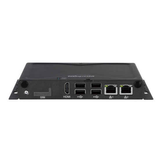
USB 2.0 ports to connect the system with USB 2.0/1.1 devices. Used to connect the system to a local area network. SIM HDMI USB 2.0 HDD/SSD Power Drive Bay Switch Copyright © 2016 NEXCOM International Co., Ltd. All Rights Reserved. NISE 50 and NISE 50W User Manual... -
Page 19: Rear Panel
– COM3: RS422/485 auto flow control DC Input COM1/2/3 Line-out Line-out Used to connect a headphone or a speaker. NISE 50W DC Input COM1/2/3 Line-out Copyright © 2016 NEXCOM International Co., Ltd. All Rights Reserved. NISE 50 and NISE 50W User Manual... -
Page 20: Mechanical Dimensions
Chapter 1: Product Introduction Mechanical Dimensions NISE 50 4.00 Ø 8.00 Ø 3.70 174.00 186.00 162.00 Copyright © 2016 NEXCOM International Co., Ltd. All Rights Reserved. NISE 50 and NISE 50W User Manual... -
Page 21: Nise 50W
Chapter 1: Product Introduction NISE 50W 4.00 R4.00 Ø3.70 273.00 285.00 261.00 Copyright © 2016 NEXCOM International Co., Ltd. All Rights Reserved. NISE 50 and NISE 50W User Manual... -
Page 22: Chapter 2: Jumpers And Connectors
Static electricity can damage many of the electronic ▪ Use correct screws and do not over tighten screws. components. Humid environments tend to have less static electricity than Copyright © 2016 NEXCOM International Co., Ltd. All Rights Reserved. NISE 50 and NISE 50W User Manual... -
Page 23: Jumper Settings
(on) and open (off). Two-Pin Jumpers: Open (Left) and Short (Right) Three-Pin Jumpers: Pins 1 and 2 are Short Copyright © 2016 NEXCOM International Co., Ltd. All Rights Reserved. NISE 50 and NISE 50W User Manual... -
Page 24: Locations Of The Jumpers And Connectors For Nisb 50
Locations of the Jumpers and Connectors for NISB 50 NISB 50 The figure below is the top view of the NISB 50 main board which is the main board used in NISE 50 and NISE 50W. It shows the locations of the jumpers and connectors. POWER... -
Page 25: Jumpers
ATX Mode 1-2 On Normal 2-3 On AT Mode 2-3 On Clear CMOS 1-2 On: default 1-2 On: default Definition Definition 3VSB AT_ATX_SELECT RTC_TEST# Copyright © 2016 NEXCOM International Co., Ltd. All Rights Reserved. NISE 50 and NISE 50W User Manual... -
Page 26: Me Clear Select
Normal 1-2 On RS422 2-3 On Clear ME 2-3 On RS485 1-2 On: default 2-3 On: default Definition Definition VCC5 SRTC_TEST# RS485_OE RS485_OE_RTS Copyright © 2016 NEXCOM International Co., Ltd. All Rights Reserved. NISE 50 and NISE 50W User Manual... -
Page 27: Sim Card Power Select
3G/Wi-Fi (CN6) 2-3 On +12V 4-5 On Ring 1-2 On: default 4-5 On: default Definition Definition UIM_PWR1 UIM_PWR VCC5 UIM_PWR2 COM1_RI#_T VCC12 COM1_RI#_T COM1_RI# Copyright © 2016 NEXCOM International Co., Ltd. All Rights Reserved. NISE 50 and NISE 50W User Manual... -
Page 28: Com3 Tx Terminal Pin Header
No need to have jumper on if it is 1.2M with CAT.6 cable No need to have jumper on if it is 1.2M with CAT.6 cable based on NEXCOM’s testing. If have signal concern for long based on NEXCOM’s testing. If have signal concern for long distance, please change the jumper on pin 1-2. -
Page 29: Connector Pin Definitions
Power Button SIM Card Slot Connector location: SW1 Connector location: IDE1 Definition Definition Definition Definition EC_PWRBT# UIM_PWR UIM_RESET EC_PWRBT# UIM_CLK PWR_SW_P PWR_SW_N UIM_VPP UIM_DATA Copyright © 2016 NEXCOM International Co., Ltd. All Rights Reserved. NISE 50 and NISE 50W User Manual... -
Page 30: Hdmi
DN1_C HDMI_DATA2_N_C HDMI_DATA1_P_C DP1_C HDMI_DATA1_N_C 4USBV1 DN2_C HDMI_DATA0_P_C DP2_C HDMI_DATA0_N_C HDMI_CLK_P_C CHASSIS_GND CHASSIS_GND HDMI_CLK_N_C CHASSIS_GND CHASSIS_GND HDMI_CEC HDMI_CTRL_CLK_C HDMI_CTRL_DAT_C HDMI_PWR HDMI_HPD_R CHASSIS_GND CHASSIS_GND Copyright © 2016 NEXCOM International Co., Ltd. All Rights Reserved. NISE 50 and NISE 50W User Manual... -
Page 31: Usb3/4 Ports (Usb 2.0)
LAN_MDI0P_1 LAN_MDI0N_1 DP3_C LAN_MDI1P_1 LAN_MDI1N_1 4USBV2 DN4_C LAN1TCT DP4_C LAN_MDI2P_1 LAN_MDI2N_1 CHASSIS_GND CHASSIS_GND LAN_MDI3P_1 LAN_MDI3N_1 CHASSIS_GND CHASSIS_GND LAN_LED_LINK1G# LAN_LINK LAN_LED_ACT# LAN_ACTPW CHASSIS_GND CHASSIS_GND Copyright © 2016 NEXCOM International Co., Ltd. All Rights Reserved. NISE 50 and NISE 50W User Manual... -
Page 32: Lan 2 Port
Connector type: RJ45 with LEDs Connector location: LAN2 LINK Definition Definition LAN2_MDI0P LAN2_MDI0N LAN2_MDI1P LAN2_MDI1N LAN2_TCT LAN2_MDI2P LAN2_MDI2N LAN2_MDI3P LAN2_MDI3N LAN2_LED_LINK1G# LAN2_LINK LAN2_LED_ACT# LAN2_ACTPW CHASSIS_GND CHASSIS_GND Copyright © 2016 NEXCOM International Co., Ltd. All Rights Reserved. NISE 50 and NISE 50W User Manual... -
Page 33: External I/O Interfaces - Rear Panel
Connector type: DB-9 port, 9-pin D-Sub Connector location: COM3 Definition Definition Definition VIN_1 COM1_DCD#_R COM1_RXD_R VIN_VSS COM1_TXD_R COM1_DTR#_R R_GND COM1_DSR#_R COM1_RTS#_R COM1_CTS#_R COM1_RI#_T CHASIS_GNDR2 CHASIS_GNDR1 Copyright © 2016 NEXCOM International Co., Ltd. All Rights Reserved. NISE 50 and NISE 50W User Manual... -
Page 34: Com 2 Port (Rs232)
Connector location: CN3 Definition Definition RS485 RS422 SP2_RXD_R Definition Definition SP2_TXD_R DATA- DATA+ SP2_RTS#_R SP2_CTS#_R CHASIS_GNDR3 CHASIS_GNDR2 RTS- RTS+ CTS+ CTS- CHASIS_GNDR4 CHASIS_GNDR4 CHASIS_GNDR3 CHASIS_GNDR3 Copyright © 2016 NEXCOM International Co., Ltd. All Rights Reserved. NISE 50 and NISE 50W User Manual... -
Page 35: Line-Out Connector
Chapter 2: Jumpers and Connectors Line-out Connector Connector type: 1x 3.5mm TRS Connector location: CN1 Definition Definition LOUT_L3 LINE_OUT_JD AGND LOUT_R3 AGND AGND Copyright © 2016 NEXCOM International Co., Ltd. All Rights Reserved. NISE 50 and NISE 50W User Manual... -
Page 36: Internal Connectors
Connector type: 2x2 4-pin header, 2.0mm pitch Connector location: JP12 Connector location: JP14 Definition Definition Definition Definition LAN_ACTPW LAN_LED_ACT# LAN2_ACTPW LAN2_LED_ACT# LAN_LED_LINK1G# LAN_LED_LINK# LAN2_LED_LINK1G# LAN2_LED_LINK# Copyright © 2016 NEXCOM International Co., Ltd. All Rights Reserved. NISE 50 and NISE 50W User Manual... -
Page 37: Sata Connector
Connector type: Standard Serial ATA 7P (1.27mm, SATA-M-180) Connector type: 1x2 2-pin header, 2.0mm pitch Connector location: CN2 Connector location: J1 Definition Definition Definition SATA_TXP0_C SATA_TXN0_C VCC5 SATA_RXN0_C SATA_RXP0_C Copyright © 2016 NEXCOM International Co., Ltd. All Rights Reserved. NISE 50 and NISE 50W User Manual... -
Page 38: Gpio Pin Header
Connector location: JP2 Connector location: JP5 Definition Definition Definition Definition VCC5 MIC1_L3 AGND ICH_GPO0_OUT ICH_GPI0_IN MIC_JD MIC1_R3 ICH_GPO1_OUT ICH_GPI1_IN ICH_GPO2_OUT ICH_GPI2_IN ICH_GPO3_OUT ICH_GPI3_IN Copyright © 2016 NEXCOM International Co., Ltd. All Rights Reserved. NISE 50 and NISE 50W User Manual... -
Page 39: Com 4 Pin Header (Rs232)
Connector type: 2x6 12-pin header, 2.0mm pitch Connector location: COM1 Connector location: JP3 Definition Definition Definition PWR_LED_N VCC5 SP4_RXD_R SATA_LED# VCC5 3VSB SP4_TXD_R SLP_S3# PS_ON# EC_PWRBT# PM_RESET#_J Copyright © 2016 NEXCOM International Co., Ltd. All Rights Reserved. NISE 50 and NISE 50W User Manual... -
Page 40: Rtc Connector
Connector type: 1x2 2-pin header, 1.25mm pitch Connector type: 1x4 4-pin header, 2.0mm pitch Connector location: J3 Connector location: JP8 Definition Definition Definition VCC3 SMB_CLK VBAT_L SMB_DATA Copyright © 2016 NEXCOM International Co., Ltd. All Rights Reserved. NISE 50 and NISE 50W User Manual... -
Page 41: Spi And I2C Pin Header
Connector location: CN12 Definition Definition Definition Definition 3VSB 3VSB 3V3_SPI_CS 3V3_SPI_MISO 3V3_GPIO_IN1 3V3_GPIO_OUT1 3V3_SPI_MOSI 3V3_SPI_CLK 3V3_GPIO_IN2 3V3_GPIO_OUT2 3P3_I2C_CLK 3P3_I2C_DATA 3V3_GPIO_IN3 3V3_GPIO_OUT3 3V3_GPIO_IN4 3V3_GPIO_OUT4 Copyright © 2016 NEXCOM International Co., Ltd. All Rights Reserved. NISE 50 and NISE 50W User Manual... -
Page 42: Uart Pin Header (Signal From Cpu)
UART Pin Header (Signal from CPU) Connector type: 2x3 6-pin header, 2.0mm pitch Connector location: JP16 Definition Definition 3VSB 3V3_UART_RXD 3V3_UART_TXD 3V3_UART_RTS 3V3_UART_CTS Copyright © 2016 NEXCOM International Co., Ltd. All Rights Reserved. NISE 50 and NISE 50W User Manual... -
Page 43: Mini-Pcie Connector (3G/4G/Msata)
3VSB_MINI1 V1P5S_1 EC_SMBCLK V1P5S_1 SATA_TXN1_C EC_SMBDATA UIM_PWR1 SATA_TXP1_C UIM_DATA MINI1USBN UIM_CLK MINI1USBP UIM_RESET 3VSB_MINI1 UIM_VPP 3VSB_MINI1 MINICARD2DIS# V1P5S_1 SATA_RXP1_C 3VSB_MINI1 SATA_RXN1_C 3VSB_MINI1 3VSB_MINI1 Copyright © 2016 NEXCOM International Co., Ltd. All Rights Reserved. NISE 50 and NISE 50W User Manual... -
Page 44: Mini-Pcie Connector (3G/4G/Wi-Fi)
V1P5S_2 TXN0_R EC_SMBDATA MINICARD2CLKREQ# UIM_PWR2 TXP0_R UIM_DATA MINI2USBN PCIE_CLKN0 UIM_CLK MINI2USBP PCIE_CLKP0 UIM_RESET 3VSB_MINI2 UIM_VPP 3VSB_MINI2 MINICARD2DIS# EC_PLTRST# V1P5S_2 RXN0_R 3VSB_MINI2 RXP0_R 3VSB_MINI2 Copyright © 2016 NEXCOM International Co., Ltd. All Rights Reserved. NISE 50 and NISE 50W User Manual... -
Page 45: Half-Size Mini-Pcie Connector (Wi-Fi)
Definition PCIE_WAKE# 3VSB_MINI3 V1P5S_3 EC_SMBCLK V1P5S_3 TXN3_R EC_SMBDATA MINICARD1CLKREQ# TXP3_R MINI3USBN PCIE_CLKN3 MINI3USBP PCIE_CLKP3 3VSB_MINI3 3VSB_MINI3 MINICARD3DIS# EC_PLTRST# V1P5S_3 RXN3_R 3VSB_MINI3 RXP3_R 3VSB_MINI3 Copyright © 2016 NEXCOM International Co., Ltd. All Rights Reserved. NISE 50 and NISE 50W User Manual... -
Page 46: Chapter 3: System Setup
2. With the screws removed, lift up the cover and remove it from the chassis. screws each on the top and on the sides. Screws on the sides Copyright © 2016 NEXCOM International Co., Ltd. All Rights Reserved. NISE 50 and NISE 50W User Manual... -
Page 47: Installing A Wi-Fi/Bt Mini-Pcie Module (Half-Size)
2. Insert the Wi-Fi module into the mini-PCI Express slot at a 45 degree angle until the gold-plated connector on the edge of the module completely Mounting disappears inside the slot. screw Copyright © 2016 NEXCOM International Co., Ltd. All Rights Reserved. NISE 50 and NISE 50W User Manual... -
Page 48: Installing A Mini-Pcie Module (Full-Size)
2. Insert the Wi-Fi module into the mini-PCI Express slot at a 45 degree angle Mounting until the gold-plated connector on the edge of the module completely screw disappears inside the slot. Copyright © 2016 NEXCOM International Co., Ltd. All Rights Reserved. NISE 50 and NISE 50W User Manual... -
Page 49: Installing A 3G Mini-Pcie Module (Half-Size)
Push the module down and then secure it with mounting screws. 3G module Module bracket Mounting screw Copyright © 2016 NEXCOM International Co., Ltd. All Rights Reserved. NISE 50 and NISE 50W User Manual... -
Page 50: Installing A Sim Card
1. Locate the SIM card slot on the front panel and remove the slot cover. 2. Insert the SIM card into the slot. SIM cover SIM card Copyright © 2016 NEXCOM International Co., Ltd. All Rights Reserved. NISE 50 and NISE 50W User Manual... - Page 51 Chapter 3: System Setup 3. Insert the SIM card cover back to its original position. SIM cover Copyright © 2016 NEXCOM International Co., Ltd. All Rights Reserved. NISE 50 and NISE 50W User Manual...
-
Page 52: Installing An Antenna
2. Insert the SMA antenna jack end of the cable through the antenna hole, and insert the 2 rings (ring 1 and ring 2) back to the antenna jack. Ring 2 Ring 1 Copyright © 2016 NEXCOM International Co., Ltd. All Rights Reserved. NISE 50 and NISE 50W User Manual... - Page 53 Chapter 3: System Setup 3. Attach the RF cable onto the module. RF cable 4. Connect the external antenna to the antenna jack. Copyright © 2016 NEXCOM International Co., Ltd. All Rights Reserved. NISE 50 and NISE 50W User Manual...
-
Page 54: Installing A 2.5" Ssd/Hdd Storage (For Nise 50W Only)
1. Remove the HDD bracket located at the front panel by loosening the two 2. Gently pull the HDD bracket out. thumb screws on the bracket cover. Screw Copyright © 2016 NEXCOM International Co., Ltd. All Rights Reserved. NISE 50 and NISE 50W User Manual... - Page 55 HDD to the bracket. the HDD connector is facing towards the cutout on the plate. Screw HDD connector Mounting plate Copyright © 2016 NEXCOM International Co., Ltd. All Rights Reserved. NISE 50 and NISE 50W User Manual...
- Page 56 Note: Please use a 2.5” SSD/HDD with a height no greater than 7mm. Copyright © 2016 NEXCOM International Co., Ltd. All Rights Reserved. NISE 50 and NISE 50W User Manual...
-
Page 57: Wallmount Installation
Chapter 3: System Setup Wallmount Installation Note 1 (NISE 50): The top cover of the system also serves as the Note 2 (NISE 50W): The top cover of the system also serves as wall mount bracket. Before wall mounting the system, please the wall mount bracket. - Page 58 1. Align the M4 mounting holes on the chassis cover to the desired 2. Mount the system by fastening 4 screws through the mounting holes. installation location. Mounting holes Copyright © 2016 NEXCOM International Co., Ltd. All Rights Reserved. NISE 50 and NISE 50W User Manual...
-
Page 59: Din Rail Clip Installation
1. Align the DIN rail clips to the mounting holes on the chassis cover. 2. Secure the DIN rail clips with screws. Mounting holes Screw specifications: P3.5x6mm NI TAP Copyright © 2016 NEXCOM International Co., Ltd. All Rights Reserved. NISE 50 and NISE 50W User Manual... -
Page 60: Aluminum Din Rail Clip Installation
1. Align the aluminum DIN rail clip to the mounting holes on the chassis cover. 2. Secure the aluminum DIN rail clip with screws. Mounting holes Screw specifications: P3x5mm Twin Washer 8mm Nylok NI Copyright © 2016 NEXCOM International Co., Ltd. All Rights Reserved. NISE 50 and NISE 50W User Manual... -
Page 61: Packing (Nise 50)
Chapter 3: System Setup Packing (NISE 50) NISE 50 EPE reference. Top View of Packing Bottom View of Packing Copyright © 2016 NEXCOM International Co., Ltd. All Rights Reserved. NISE 50 and NISE 50W User Manual... - Page 62 Chapter 3: System Setup Front View of Packing Rear View of Packing Copyright © 2016 NEXCOM International Co., Ltd. All Rights Reserved. NISE 50 and NISE 50W User Manual...
-
Page 63: Packing (Nise 50W)
Chapter 3: System Setup Packing (NISE 50W) NISE 50W EPE reference. Top View of Packing Bottom View of Packing Copyright © 2016 NEXCOM International Co., Ltd. All Rights Reserved. NISE 50 and NISE 50W User Manual... - Page 64 Chapter 3: System Setup Front View of Packing Rear View of Packing Copyright © 2016 NEXCOM International Co., Ltd. All Rights Reserved. NISE 50 and NISE 50W User Manual...
-
Page 65: Chapter 4: Bios Setup
This chapter describes how to use the BIOS setup program for NISE 50 and NISE The settings made in the setup program affect how the computer performs. 50W. The BIOS screens provided in this chapter are for reference only and may It is important, therefore, first to try to understand all the setup options, and change if the BIOS is updated in the future. -
Page 66: Default Configuration
Load optimized default values. Press the key to enter Setup: Saves and exits the Setup program. Press <Enter> to enter the highlighted sub-menu Copyright © 2016 NEXCOM International Co., Ltd. All Rights Reserved. NISE 50 and NISE 50W User Manual... - Page 67 When “” appears on the left of a particular field, it indicates that a submenu which contains additional options are available for that field. To display the submenu, move the highlight to that field and press Copyright © 2016 NEXCOM International Co., Ltd. All Rights Reserved. NISE 50 and NISE 50W User Manual...
-
Page 68: Bios Setup Utility
System Date [Thu 03/03/2016] F3: Optimized Defaults System Time [17:18:36] F4: Save & Exit ESC: Exit Version 2.16.1242. Copyright (C) 2013 American Megatrends, Inc. Copyright © 2016 NEXCOM International Co., Ltd. All Rights Reserved. NISE 50 and NISE 50W User Manual... -
Page 69: Advanced
F3: Optimized Defaults F4: Save & Exit option may not be effective with some OS. ESC: Exit Version 2.16.1242. Copyright (C) 2013 American Megatrends, Inc. Copyright © 2016 NEXCOM International Co., Ltd. All Rights Reserved. NISE 50 and NISE 50W User Manual... - Page 70 Super IO Chip button is pressed. The options are Suspend Disabled and S3 (Suspend to Displays the Super I/O chip used on the board. RAM). Copyright © 2016 NEXCOM International Co., Ltd. All Rights Reserved. NISE 50 and NISE 50W User Manual...
- Page 71 Detects and displays the current CPU temperature. System Temperature Detects and displays the current system temperature. VCore to VCC5 Detects and displays the output voltages. Copyright © 2016 NEXCOM International Co., Ltd. All Rights Reserved. NISE 50 and NISE 50W User Manual...
- Page 72 Windows, this problem may occur. To avoid this problem, enable this field to limit the return value to 3 or lesser than 3. Copyright © 2016 NEXCOM International Co., Ltd. All Rights Reserved. NISE 50 and NISE 50W User Manual...
- Page 73 F1: General Help F2: Previous Values F3: Optimized Defaults F4: Save & Exit ESC: Exit Version 2.16.1242. Copyright (C) 2013 American Megatrends, Inc. Copyright © 2016 NEXCOM International Co., Ltd. All Rights Reserved. NISE 50 and NISE 50W User Manual...
- Page 74 This option configures the Serial ATA drives to use AHCI (Advanced Host Controller Interface). AHCI allows the storage driver to enable the advanced Serial ATA features which will increase storage performance. Copyright © 2016 NEXCOM International Co., Ltd. All Rights Reserved. NISE 50 and NISE 50W User Manual...
- Page 75 SCC eMMC 4.5 DDR50 Support Enables or disables SCC eMMC 4.5 DDR50 support. SCC eMMC 4.5 HS200 Support Enables or disables SCC eMMC 4.5 HS200 support. Copyright © 2016 NEXCOM International Co., Ltd. All Rights Reserved. NISE 50 and NISE 50W User Manual...
- Page 76 Enables or disables CSM support. Network Controls the execution of UEFI and legacy PXE OpROM. Onboard LAN PXE Enables or disables onboard LAN PXE ROM. Copyright © 2016 NEXCOM International Co., Ltd. All Rights Reserved. NISE 50 and NISE 50W User Manual...
- Page 77 This is a workaround for OSs that does not support XHCI hand-off. The XHCI ownership change should be claimed by the XHCI driver. Copyright © 2016 NEXCOM International Co., Ltd. All Rights Reserved. NISE 50 and NISE 50W User Manual...
- Page 78 Enables or disables BIOS support for security device. O.S will not show Security Device. TCG EFI protocol and INT1A interface will not be available. Copyright © 2016 NEXCOM International Co., Ltd. All Rights Reserved. NISE 50 and NISE 50W User Manual...
-
Page 79: Chipset
Restore AC Power Loss South Bridge Select the AC power state when power is re-applied after a power failure. Enters the South Bridge submenu. Copyright © 2016 NEXCOM International Co., Ltd. All Rights Reserved. NISE 50 and NISE 50W User Manual... - Page 80 Enables or disables PCH USB rate matching hubs mode. Azalia HDMI Codec USB EHCI Debug Enables or disables internal HDMI codec for Azalia. Enables or disables PCH EHCI debug capability. Copyright © 2016 NEXCOM International Co., Ltd. All Rights Reserved. NISE 50 and NISE 50W User Manual...
-
Page 81: Security
Enables or disables the PCI Express ports 0 to 3 on the chipset. Select this to reconfigure the administrator’s password. User Password Select this to reconfigure the user’s password. Copyright © 2016 NEXCOM International Co., Ltd. All Rights Reserved. NISE 50 and NISE 50W User Manual... -
Page 82: Boot
When enabled, the BIOS will shorten or skip some check items during POST. This will decrease the time needed to boot the system. Copyright © 2016 NEXCOM International Co., Ltd. All Rights Reserved. NISE 50 and NISE 50W User Manual... -
Page 83: Save & Exit
Restore Defaults To restore the BIOS to default settings, select this field then press <Enter>. A dialog box will appear. Confirm by selecting Yes. Copyright © 2016 NEXCOM International Co., Ltd. All Rights Reserved. NISE 50 and NISE 50W User Manual... -
Page 84: Appendix A: Power Consumption
Standby mode. ▪ BIOS mode. ▪ 100% Full loading mode (include USB load fixture) 4. Measure and record system maximum power consumption value. Copyright © 2016 NEXCOM International Co., Ltd. All Rights Reserved. NISE 50 and NISE 50W User Manual... -
Page 85: Appendix B: Gpio Control Commands
HiLow – If type control is input type, 1-high active and 0-low control 0x01 Output 0x01Pull-dn active. If type control is output type, 1-default output high and 0-default output low. Copyright © 2016 NEXCOM International Co., Ltd. All Rights Reserved. NISE 50 and NISE 50W User Manual... -
Page 86: Read Gpio Status Sequence
Read 0x62 port number which you set in port Write 0x00, GPIO pin will be set low. index. 1-GPIO is high. 0-GPIO is low. 0xFF-fail. Copyright © 2016 NEXCOM International Co., Ltd. All Rights Reserved. NISE 50 and NISE 50W User Manual... -
Page 87: Read Gpio Direction Sequence
Write 0x40, GPIO pin will be set output. Read 0x62 port number which you set in index. port Write 0x80, GPIO pin will be set input. 0x80-input, 0x40-output. 0xFF-fail Copyright © 2016 NEXCOM International Co., Ltd. All Rights Reserved. NISE 50 and NISE 50W User Manual...
Need help?
Do you have a question about the NISE 50 and is the answer not in the manual?
Questions and answers