
Related Manuals for Nexcom nROK 500


Summary of Contents for Nexcom nROK 500
- Page 1 NEXCOM International Co., Ltd. Mobile Computing Solutions Fanless Railway Computer nROK 500 User Manual NEXCOM International Co., Ltd. www.nexcom.com Published March 2014...
-
Page 2: Table Of Contents
Thermal Sensor (Reserved Function) (JP3) ...........19 Hardware Specifications .................5 Power Up Signal Detection Pin Header (JP7) (Reserved Feature) ....19 Power Up Manner Pin Header (JP8) (Reserved Feature) .......20 Copyright © 2013 NEXCOM International Co., Ltd. All rights reserved nROK 500 User Manual... - Page 3 VGA connector (VGA1) ................24 Monitor Power Connector (J11) ..............25 LED Status ....................25 Appendix A: GPI/O Programming Guide I/O Address Function ..................26 Appendix B: Watchdog Timer Copyright © 2013 NEXCOM International Co., Ltd. All rights reserved nROK 500 User Manual...
-
Page 4: Preface
European Union (CE) directives if it has a CE marking. For computer systems to remain CE compliant, only CE-compliant parts may be used. Maintaining nROK 500 is a trademark of NEXCOM International Co., Ltd. All other product CE compliance also requires proper cable and cabling techniques. -
Page 5: Rohs Compliance
0.1% or 1,000ppm, and Polybrominated diphenyl Ethers (PBDE) < 0.1% or 1,000ppm. In order to meet the RoHS compliant directives, NEXCOM has established an engineering and manufacturing task force in to implement the introduction of green products. The task force will ensure that we follow the standard... -
Page 6: Warranty And Rma
? Replace with 3 party products if needed. returned packages. ? If RMA goods can not be repaired, NEXCOM will return it to the customer ? Customers must collect all the information about the problems without any charge. encountered and note anything abnormal or, print out any on-screen messages, and describe the problems on the “NEXCOM RMA Service... -
Page 7: Safety Information
The load of the system unit does not solely rely for support from the If RMA goods can not be repaired, NEXCOM will return it to the customer rackmounts located on the sides. Firm support from the bottom is highly without any charge. -
Page 8: Safety Precautions
11. All cautions and warnings on the equipment should be noted. 19. The computer is provided with CD drives that comply with the appropriate safety standards including IEC 60825. viii Copyright © 2013 NEXCOM International Co., Ltd. All rights reserved nROK 500 User Manual... -
Page 9: Technical Support And Assistance
Technical Support and Assistance Conventions Used in this Manual Warning: Information about certain situations, which if not 1. For the most updated information of NEXCOM products, visit NEXCOM’s observed, can cause personal injury. This will prevent injury to website at www.nexcom.com. -
Page 10: Global Service Contact Information
16F, No.250, Sec. 2, Chongde Rd., Tel: +86-21-5278-5868 Beitun Dist., Taichung City 406, R.O.C. Fax: +86-21-3251-6358 Tel: +886-4-2249-1179 Email: sales@nexcom.cn Fax: +886-4-2249-1172 www.nexcom.cn Email: sales@nexcom.com.tw www.nexcom.com.tw Copyright © 2013 NEXCOM International Co., Ltd. All rights reserved nROK 500 User Manual... -
Page 11: United Kingdom
Fax: +44-1908-262042 Email: sales.uk@nexcom.eu Chengdu Office www.nexcom.eu 9F, Shuxiangxie, Xuefu Garden, No.12 Section 1, South Yihuan Rd., Chengdu, 610061, China Tel: +86-28-8523-0186 Fax: +86-28-8523-0186 Email: sales@nexcom.cn www.nexcom.cn Copyright © 2013 NEXCOM International Co., Ltd. All rights reserved nROK 500 User Manual... -
Page 12: Package Contents
Specification 50311F0110X00 FLAT HEAD SCREW F3x5 NI NYLOK 60233SAM17X00 GSM/UMTS/HSDPA ANTENNA ETEK:EEN-501 53.5(H)x16.8(W)mm 602DCD0375X00 CD DRIVER 60233PW237X00 POWER CABLE 3W3 FEMALE TO CABLE 18 AWG L=1000mm Copyright © 2013 NEXCOM International Co., Ltd. All rights reserved nROK 500 User Manual... -
Page 13: Ordering Information
The following provides ordering information. • nROK 500 (P/N: 10A00050000X0) - Intel Atom™ D525 1.8GHz Fanless Railway Computer with 2G ® memory pre-installed and Isolated 24VDC Input xiii Copyright © 2013 NEXCOM International Co., Ltd. All rights reserved nROK 500 User Manual... -
Page 14: Chapter 1: Quick Reference Guide
Definition Clear CMOS EEPROM_WP J1: GPIO pin head J4: Line out pin head Definition Definition Definition FRONT_OUT_LC GPIO20(Pin84)Out0 GPIO24(Pin36)In0 GPIO21(Pin70)Out1 GPIO25(Pin34)In1 GPIO22(Pin66)Out2 GPIO26(Pin33)In2 FRONT_OUT_RC GPIO23(Pin48)Out3 GPIO27(Pin32)In3 Copyright © 2013 NEXCOM International Co., Ltd. All rights reserved nROK 500 User Manual... - Page 15 FUSE CF card 24V DC IN DC Input: 24V DC output (range:16.8V~30V) Pin-out: A1: + input (24V nominal) A2: - GND A3: Ignition Signal Input (24V,nominal;0~10.5V=off,test=on) Copyright © 2013 NEXCOM International Co., Ltd. All rights reserved nROK 500 User Manual...
-
Page 16: Chapter 2: Product Introduction
• 1x M12 LAN port • Support WoL & PXE function • 1x external CF socket and one external SIM card holder • Certified by EN50155 Copyright © 2013 NEXCOM International Co., Ltd. All rights reserved nROK 500 User Manual... - Page 17 500 are designed against vibration. Equipped with a SIM card holder, CF socket and mini-PCIe socket for optional 3G wireless module, nROK 500 allows data to be transmitted over network and stored in a convenient SSD (Solid-State Drive) or CF card for better vibration and shock protection.
-
Page 18: Hardware Specifications
- Audio controller: High definition audio controller, Realtek: ALC888-GR • 264mm (W) x 142mm (D) x 65.5mm (H) - 1x Speaker-out, Dia. 3.5mm phone jack, covered with plastic cover to against the dust Copyright © 2013 NEXCOM International Co., Ltd. All rights reserved nROK 500 User Manual... - Page 19 • Vibration (Random): Compliance with EN61373 Category 1, Class B • Shock: Compliance with EN61373 Category 1, Class B Ingress Protection • IP52 Certifications • CE • EN50155 Copyright © 2013 NEXCOM International Co., Ltd. All rights reserved nROK 500 User Manual...
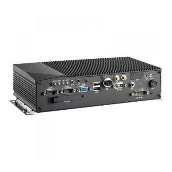
- Page 20 Chapter 2: Product Introduction nROK 500 263.50 275.60 287.60 PWR HDD LNK ACT COM2 COM1 FUSE CF card 24V DC IN Copyright © 2013 NEXCOM International Co., Ltd. All rights reserved nROK 500 User Manual...
-
Page 21: Chapter 3: Jumpers And Connectors
Static electricity can damage many of the electronic components. Humid environment tend to have less static electricity than dry environments. A grounding strap is warranted whenever danger of static electricity exists. Copyright © 2013 NEXCOM International Co., Ltd. All rights reserved nROK 500 User Manual... -
Page 22: Jumper
(on) and open (off). Two-Pin Jumpers: Open (Left) and Short (Right) Three-Pin Jumpers: Pins 1 and 2 Are Short Copyright © 2013 NEXCOM International Co., Ltd. All rights reserved nROK 500 User Manual... -
Page 23: Locations Of The Jumpers And Connectors
Chapter 3: Jumpers and Connectors Locations of the Jumpers and Connectors The figure below is the main board which is the board used in the nROK 500 system. It shows the locations of the jumpers and connectors. A110 B110 C110... -
Page 24: Connectors
A. Connector size: 1 X 4 = 4 Pin, 2.0mm, 180°, JST Connector B. Connector location: B. Connector location: Connector pin definition Connector pin definition Definition Definition LAN1_M0P LED_LINK# LAN1_M0N +3.3V LAN1_M1P LED_ACT# LAN1_M1N +3.3V Copyright © 2013 NEXCOM International Co., Ltd. All rights reserved nROK 500 User Manual... -
Page 25: Power / Hdd Access Led (J6)
A. Connector size: 1 X 4 = 4 Pin, 2.0mm, 180°, JST Connector B. Connector location: B. Connector location: Connector pin definition Connector pin definition Definition Definition Power ON# MIC1-L HDD ACCESS# MIC1-R Copyright © 2013 NEXCOM International Co., Ltd. All rights reserved nROK 500 User Manual... -
Page 26: Line-Out Pin Header (J4)
A. Connector size: 1 X 6 = 6 Pin, 3.96mm, 180°, Power Connector B. Connector location: B. Connector location: Connector pin definition Connector pin definition Definition Definition Definition +12VS +12VS FRONT_OUT_LC IGNITION FRONT_OUT_RC Copyright © 2013 NEXCOM International Co., Ltd. All rights reserved nROK 500 User Manual... -
Page 27: Vga Power Input Connector (Con2)
A. Connector size: 1 X 6 = 6 Pin, 2.0mm, 180°, JST Connector B. Connector location B. Connector location Connector pin definition Connector pin definition Definition Definition Definition Data 2N +12VSD Data 2P Data 3N Data 3P Copyright © 2013 NEXCOM International Co., Ltd. All rights reserved nROK 500 User Manual... -
Page 28: Rear Usb Connector (Usb1)
A. Connector size: 1 X 4 = 4 Pin, 2.54mm, 180°, JST Connector B. Connector location B. Connector location Connector pin definition Connector pin definition Definition Definition Definition +12V Data 0N Data 1N Data 0P Data 1P Copyright © 2013 NEXCOM International Co., Ltd. All rights reserved nROK 500 User Manual... -
Page 29: Sata Connector (Cn2)
B. Connector location B. Connector location Connector pin definition Connector pin definition Definition Definition Definition Definition TXP0 TXN0 GPIO20(Pin84)Out0 GPIO24(Pin36)In0 RXN0 RXP0 GPIO21(Pin70)Out1 GPIO25(Pin34)In1 GPIO22(Pin66)Out2 GPIO26(Pin33)In2 GPIO23(Pin48)Out3 GPIO27(Pin32)In3 Copyright © 2013 NEXCOM International Co., Ltd. All rights reserved nROK 500 User Manual... -
Page 30: Clear Cmos Pin Header (J12)
A. Connector size: 1 X 3 = 3 Pin, 2.54mm, 180°, pinhead B. Connector location B. Connector location Connector pin definition Connector pin definition Setting Definition Normal I2C CLK Clear CMOS I2C DATA 1-2 On: default Copyright © 2013 NEXCOM International Co., Ltd. All rights reserved nROK 500 User Manual... -
Page 31: System Reset Pin Header (Jp1)
A. Connector size: 1 X 2 = 2 Pin, 2.54mm, 180°, pinhead B. Connector location B. Connector location Connector pin definition Connector pin definition Definition Definition RSET EEPROM_WP Copyright © 2013 NEXCOM International Co., Ltd. All rights reserved nROK 500 User Manual... -
Page 32: Thermal Sensor (Reserved Function) (Jp3)
A. Connector size: 1 X 3 = 3 Pin, 2.54mm, 180°, pinhead B. Connector location B. Connector location Connector pin definition Connector pin definition Definition Setting Sensor Ignition detection Power in detection 1-2 On: default Copyright © 2013 NEXCOM International Co., Ltd. All rights reserved nROK 500 User Manual... -
Page 33: Power Up Manner Pin Header (Jp8) (Reserved Feature)
A. Connector size: 1 X 3 = 3 Pin, 2.54mm, 180°, pinhead B. Connector location B. Connector location Connector pin definition Connector pin definition Setting Definition Ignition & Push button Push button only 1-2 On: default Copyright © 2013 NEXCOM International Co., Ltd. All rights reserved nROK 500 User Manual... -
Page 34: Mcu Download Port (Jp6)
Connector pin definition Connector pin definition Definition Definition Definition +3.3ALW 12V input voltage level MRST C2CK Wide range 8~60V voltage input (reserved feature) 1-2 On: default Copyright © 2013 NEXCOM International Co., Ltd. All rights reserved nROK 500 User Manual... -
Page 35: Gal Download Port (Jp4)
Chapter 3: Jumpers and Connectors GAL Download Port (JP4) A. Connector size: 1 X 6 = 6 Pin, 2.54mm, 180°, pinhead B. Connector location Connector pin definition Definition Definition +3.3V Copyright © 2013 NEXCOM International Co., Ltd. All rights reserved nROK 500 User Manual... -
Page 36: Cf Connector (Ide1)
SDD6A SDD14A SDD7A SDD15A IDERST# SDCS#1 SDCS#3 SIORDY SDA2A SDREQ SDIOR# SDA1A SDDACK# SDIOW# SDA0A IDEACTP# SDD0A DIAG# HDIRQ14 SDD1A SDD8A SDD2A SDD9A CF_SEL# SDD10A CF_CD2# Copyright © 2013 NEXCOM International Co., Ltd. All rights reserved nROK 500 User Manual... -
Page 37: Com Port Connector (Com1 / Com2)
DCD2 DSR#2 RED_VGA VGA_VCC RTS#2 GREEN_VGA CTS#2 BLUE_VGA DTR#2 RI#2 VGA_DDC_DATA G_HSYNC G_VSYNC VGA_DDC_CLK Connector pin definition (COM2) Definition Definition DCD1 DSR#1 RTS#1 CTS#1 DTR#1 RI#1 Copyright © 2013 NEXCOM International Co., Ltd. All rights reserved nROK 500 User Manual... -
Page 38: Monitor Power Connector (J11)
LED 1~4 / 6~9 : BIOS POST Display (Port 80) LED 1~4 : High Byte Connector pin definition (COM1) LED 6~9 : Low Byte Definition +12V Copyright © 2013 NEXCOM International Co., Ltd. All rights reserved nROK 500 User Manual... -
Page 39: Appendix A: Gpi/O Programming Guide
Digital I/O (Digital Input/Output) pins are provided for custom system design. IO base address : 800h This appendix provides definitions and its default setting for the Digital I/O pins in the nROK 500. The pin definition is shown in the following table: Bit0 : GPO20 Bit1 : GPO21... -
Page 40: Appendix B: Watchdog Timer
Users can select second or minute. Step3. See “TimeCountWDT” procedure #Set Watchdog Timer Time-out Value. Users can set time-out value. Step4: See ExitSetup procedure #Exit Setup Environment Copyright © 2012 NEXCOM International Co., Ltd. All rights reserved nROK 500 User Manual... - Page 41 -o 2f XX ;minute mode (-o 2f 00 second mode) al, 00h ;Here!! set 00h for second, set 80h for minute -o 2e 73 ;LSB for Watch dog tme out value Copyright © 2012 NEXCOM International Co., Ltd. All rights reserved nROK 500 User Manual...
- Page 42 -o 2f ZZ XX: DO : Second mode with KRST (Bit 6) 50 : minute mode with KRST (Bit 6) 10 second timeout: xx=D0 yy=0a zz=00 Copyright © 2012 NEXCOM International Co., Ltd. All rights reserved nROK 500 User Manual...
Need help?
Do you have a question about the nROK 500 and is the answer not in the manual?
Questions and answers