
Related Manuals for Nexcom NISE 51


Summary of Contents for Nexcom NISE 51
- Page 1 NEXCOM International Co., Ltd. IoT Automation Solutions Business Group Fan-less Computer NISE 51 User Manual NEXCOM International Co., Ltd. www.nexcom.com Published July 2019...
-
Page 2: Table Of Contents
Front Panel ..................4 LAN 2 Port ..................15 Rear Panel ...................4 External I/O Interfaces - Rear Panel.............16 Mechanical Dimensions ................5 DC Power Input ................16 COM 1 Port (RS232) ...............16 Copyright © 2019 NEXCOM International Co., Ltd. All Rights Reserved. NISE 51 User Manual... - Page 3 Installing a 3.5G Mini-PCIe Module (Full-size) ........38 Installing a WLAN/Bluetooth Mini-PCIe Module (Half-size) .....40 Installing a SIM Card ................42 Installing an Antenna ................44 Wall Mount Installation .................46 Copyright © 2019 NEXCOM International Co., Ltd. All Rights Reserved. NISE 51 User Manual...
-
Page 4: Preface
Acknowledgements The product(s) described in this manual complies with all applicable NISE 51 is a trademark of NEXCOM International Co., Ltd. All other product European Union (CE) directives if it has a CE marking. For computer systems names mentioned herein are registered trademarks of their respective to remain CE compliant, only CE-compliant parts may be used. -
Page 5: Rohs Compliance
(Cr6+) < 0.1% or 1,000ppm, Polybrominated biphenyls (PBB) < 0.1% or 1,000ppm, and Polybrominated diphenyl Ethers (PBDE) < 0.1% or 1,000ppm. In order to meet the RoHS compliant directives, NEXCOM has established an engineering and manufacturing task force to implement the introduction of green products. -
Page 6: Warranty And Rma
(manuals, cable, etc.) and any components from the card, such as CPU and RAM. If the components were suspected as part of the problems, ▪ If RMA goods can not be repaired, NEXCOM will return it to the customer please note clearly which components are included. Otherwise, NEXCOM without any charge. -
Page 7: Installation Recommendations
Using your fingers can disconnect most of the connections. It is recommended that you do not use needle-nose pliers to disconnect connections as these can damage the soft metal or plastic parts of the connectors. Copyright © 2019 NEXCOM International Co., Ltd. All Rights Reserved. NISE 51 User Manual... -
Page 8: Safety Information
Discard used batteries according to the manufacturer’s instructions. ▪ This product is intended to be supplied by an approved power adapter, rated 12Vdc, 5A or 24Vdc, 2.5A minimum and Tma 55 degree Celsius. If further assistance is needed, please contact NEXCOM for further information. viii Copyright ©... -
Page 9: Safety Precautions
ACCORDING TO THE MANUFACTURER’S INSTRUCTIONS. 11. If the equipment is not used for a long time, disconnect it from the power source to avoid damage by transient overvoltage. Copyright © 2019 NEXCOM International Co., Ltd. All Rights Reserved. NISE 51 User Manual... -
Page 10: Technical Support And Assistance
Preface Technical Support and Assistance Conventions Used in this Manual 1. For the most updated information of NEXCOM products, visit NEXCOM’s Warning: website at www.nexcom.com. Information about certain situations, which if not observed, can cause personal injury. This will prevent injury to yourself 2. -
Page 11: Global Service Contact Information
16F, No.250, Sec. 2, Chongde Rd., Beijing, 100094, China Beitun Dist., Tel: +86-10-5704-2680 Taichung City 406, R.O.C. Fax: +86-10-5704-2681 Tel: +886-4-2249-1179 Email: sales@nexcom.cn Fax: +886-4-2249-1172 www.nexcom.cn Email: sales@nexcom.com.tw www.nexcom.com.tw Copyright © 2019 NEXCOM International Co., Ltd. All Rights Reserved. NISE 51 User Manual... - Page 12 Tokyo, 108-0014, Japan No. 609, Yunlin East Rd., Tel: +81-3-5419-7830 Shanghai, 200062, China Fax: +81-3-5419-7832 Tel: +86-21-5278-5868 Email: sales@nexcom-jp.com Fax: +86-21-3251-6358 www.nexcom-jp.com Email: renwang@nexcom.com.tw www.nexcom.cn Copyright © 2019 NEXCOM International Co., Ltd. All Rights Reserved. NISE 51 User Manual...
-
Page 13: Package Contents
Preface Package Contents Before continuing, verify that the package that you received is complete. Your NISE 51 package should have all the items listed in the following table. Item Part Number Description 19J00005100X0 NISE 51 ASSY 4NCPM00302X00 Terminal Blocks 3P Phoenix Contact:1777992... -
Page 14: Ordering Information
Preface Ordering Information The following information below provides ordering information for NISE 51. NISE 51 (P/N: 10J00005100X0) - Intel Celeron processor N3350 Dual Core fanless system, with onboard ® ® 16GB EMMC NISE 51-E3950 (P/N: 10J00005101X0) - Intel Atom processor E3950 Quad Core fanless system, with onboard ®... -
Page 15: Chapter 1: Product Introduction
▪ 2 x M.2 slots for Wi-Fi/Bluetooth and storage/LTE modules ▪ 2 x RS232, 1 x RS422/485 with auto flow control ▪ Support -5~55 degree C operating temperature ▪ Support 12V and 24V DC input Copyright © 2019 NEXCOM International Co., Ltd. All Rights Reserved. NISE 51 User Manual... -
Page 16: Hardware Specifications
▪ 1 x Line-out (according to IEC60068-2-1, IEC60068-2-2, IEC60068-2-14) ▪ Support 12V/24V DC input ▪ Storage temperature: -20°C to 75°C ▪ Relative humidity: 10% to 95% (non-condensing) Copyright © 2019 NEXCOM International Co., Ltd. All Rights Reserved. NISE 51 User Manual... - Page 17 M.2 Slot Configuration PCIe SATA 3.5G/4G Wi-Fi/Bluetooth Storage M.2_Key_A1 A Key 2230 Support M.2_Key_B1 B Key 2242/3042 (3042) (2242) Support (3042) Support (2242) Copyright © 2019 NEXCOM International Co., Ltd. All Rights Reserved. NISE 51 User Manual...
-
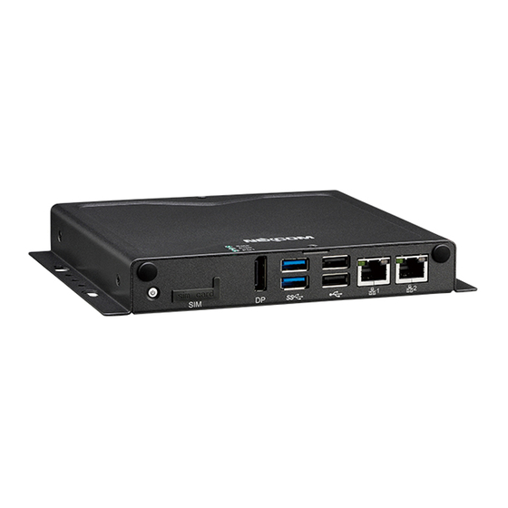
Page 18: Knowing Your Nise 51
– COM1 & COM2: Full RS232 signal – COM3: RS422/485 auto flow control DC Input COM1/2/3 Line-out Line-out Used to connect a headphone or a speaker. Copyright © 2019 NEXCOM International Co., Ltd. All Rights Reserved. NISE 51 User Manual... -
Page 19: Mechanical Dimensions
Chapter 1: Product Introduction Mechanical Dimensions 4.00 R4.00 Ø 3.70 174.00 186.00 162.00 Copyright © 2019 NEXCOM International Co., Ltd. All Rights Reserved. NISE 51 User Manual... -
Page 20: Chapter 2: Jumpers And Connectors
Static electricity can damage many of the electronic ▪ Use correct screws and do not over tighten screws. components. Humid environments tend to have less static electricity than Copyright © 2019 NEXCOM International Co., Ltd. All Rights Reserved. NISE 51 User Manual... -
Page 21: Jumper Settings
(on) and open (off). Two-Pin Jumpers: Open (Left) and Short (Right) Three-Pin Jumpers: Pins 1 and 2 are Short Copyright © 2019 NEXCOM International Co., Ltd. All Rights Reserved. NISE 51 User Manual... -
Page 22: Locations Of The Jumpers And Connectors For Nisb 51
Locations of the Jumpers and Connectors for NISB 51 NISB 51 The figure below is the top view of the NISB 51 main board which is the main board used in NISE 51. It shows the locations of the jumpers and connectors. RS422/485... -
Page 23: Jumpers And Switches
Connector type: 1x3 3-pin header, 2.0mm pitch Connector location: JP7 Connector location: JP6 Settings Definition 1-2 On 2-3 On 2-3 On: default Definition VCC5 SP1_RI#_R SP1_RI# Copyright © 2019 NEXCOM International Co., Ltd. All Rights Reserved. NISE 51 User Manual... -
Page 24: Com3 Tx Terminal Pin Header
COM3 RX Terminal Pin Header Connector type: 1x3 3-pin header, 2.0mm pitch Connector type: 1x3 3-pin header, 2.0mm pitch Connector location: JP5 Connector location: JP4 Definition Definition TX+_DATA+ TX-_DATA- Copyright © 2019 NEXCOM International Co., Ltd. All Rights Reserved. NISE 51 User Manual... -
Page 25: At/Atx Type Select
1 Off, 2 Off 1 Off, 2 On 1 Off, 2 Off: default 1 Off, 2 On: default Definition Definition RTEST# AT_PWRBT# SRTCRST# PBT_TR PWRBTN# PWRBTN# Copyright © 2019 NEXCOM International Co., Ltd. All Rights Reserved. NISE 51 User Manual... -
Page 26: Connector Pin Definitions
External I/O Interfaces - Front Panel Power Button SIM Card Slot Connector location: SW2 Connector location: SIM1 Definition Definition Definition Definition PBT_TR UIM_PWR UIM_RESET PBT_TR UIM_CLK PWRLED_N PWRLED_P UIM_VPP UIM_DATA Copyright © 2019 NEXCOM International Co., Ltd. All Rights Reserved. NISE 51 User Manual... -
Page 27: Led Indicators
LED3 Definition Definition Definition Definition LED1 VCC3 SATA_LED_N DP_DATA0_P_C LED2 3VSB GPO_PR1 DP_DATA0_N_C DP_DATA1_P_C LED3 3VSB GPO_PR2 DP_DATA1_N_C DP_DATA2_P_C DP_DATA2_N_C DP_DATA3_P_C DP_DATA3_N_C DPC_AUXP_C DPC_AUXN_C DDI0HPD0 DP_PWR Copyright © 2019 NEXCOM International Co., Ltd. All Rights Reserved. NISE 51 User Manual... -
Page 28: Usb 3.0 Ports
Connector location: USB23_1 Definition Definition Definition Definition P5V_USB01 USB2_N3_C P5V_USB23 USB2_N2_C USB2_P3_C USB2_P2_C USB3_RX0N_C USB3_RX0P_C P5V_USB23 USB2_N0_C USB3_TX0N_C USB2_P0_C USB3_TX0P_C P5V_USB01 USB2_N1_C USB2_P1_C USB3_RX1N_C USB3_RX1P_C USB3_TX1N_C USB3_TX1P_C Copyright © 2019 NEXCOM International Co., Ltd. All Rights Reserved. NISE 51 User Manual... -
Page 29: Lan 1 Port
LAN2_MDI0P LAN2_MDI0N LAN1_MDI1P LAN1_MDI1N LAN2_MDI1P LAN2_MDI1N LAN1TCT LAN1TCTG LAN2TCT LAN2TCTG LAN1_MDI2P LAN1_MDI2N LAN2_MDI2P LAN2_MDI2N LAN1_MDI3P LAN1_MDI3N LAN2_MDI3P LAN2_MDI3N LAN1_LINK1G# LAN1_LINK100# LAN2_LINK1G# LAN2_LINK100# LAN1_LED_ACT# LAN1_ACT_P LAN2_LED_ACT# LAN2_ACT_P Copyright © 2019 NEXCOM International Co., Ltd. All Rights Reserved. NISE 51 User Manual... -
Page 30: External I/O Interfaces - Rear Panel
COM 1 Port (RS232) Connector location: PW1 Connector type: DB-9 port, 9-pin D-Sub Connector location: COM1 Definition Definition Definition SP1_DCD# SP1_RXD SP1_TXD SP1_DTR# Earth GND SP1_DSR# SP1_RTS# SP1_CTS# SP1_RI# Copyright © 2019 NEXCOM International Co., Ltd. All Rights Reserved. NISE 51 User Manual... -
Page 31: Com 2 Port (Rs232)
Connector location: COM3 Definition Definition RS485 RS422 SP2_DCD# SP2_RXD Definition Definition SP2_TXD SP2_DTR# DATA-_R TX-_R SP2_DSR# DATA+_R TX+_R SP2_RTS# SP2_CTS# RX+_R SP2_RI# RX-_R RTS-_R RTS+_R CTS+_R CTS-_R Copyright © 2019 NEXCOM International Co., Ltd. All Rights Reserved. NISE 51 User Manual... -
Page 32: Line-Out Connector
Chapter 2: Jumpers and Connectors Line-out Connector Connector type: 1x 3.5mm TRS Connector location: LINE_OUT1 Definition Definition LOUT_R3 LINE_OUT_JD LOUT_L3 Copyright © 2019 NEXCOM International Co., Ltd. All Rights Reserved. NISE 51 User Manual... -
Page 33: Internal Connectors
Connector type: 1x10 10-pin header, 1.0mm pitch Connector location: USB1 Connector location: J1 Definition Definition Definition Definition P5V_USB4_P1 USB2_N4_C PLTRST_N USB2_P4_C LPC_CLKOUT1 LPC_FRAME# LPC_AD3 LPC_AD2 LPC_AD1 LPC_AD0 LPC_SERIRQ VCC3 Copyright © 2019 NEXCOM International Co., Ltd. All Rights Reserved. NISE 51 User Manual... -
Page 34: Com4 Pin Header (Tx/Rx Only)
Connector type: 1x3 3-pin header, 2.0mm pitch Connector type: Standard Serial ATA 7P (1.27mm, SATA-M-180) Connector location: COM4 Connector location: SATA1 Definition Definition Definition SATA_TXP0_C SP4_RXD_R SATA_TXN0_C SATA_RXN0_C SATA_RXP0_C SP4_TXD_R Copyright © 2019 NEXCOM International Co., Ltd. All Rights Reserved. NISE 51 User Manual... -
Page 35: Sata Power Connector
Remote Button/S3 Connector Connector type: 1x2 2-pin header, 2.5mm pitch Connector type: 1x3 3-pin header, 2.0mm pitch Connector location: SATA_PWR1 Connector location: CN1 Definition Definition REMOTE_S3 VCC5 PBT_TR_C Copyright © 2019 NEXCOM International Co., Ltd. All Rights Reserved. NISE 51 User Manual... -
Page 36: Gpio Connector
Connector type: 1x4 4-pin header, 2.0mm pitch Connector location: GPIO1 Connector location: MIC_IN1 Definition Definition Definition Definition VCC5 MIC1_L3 ICH_GPO0_OUT ICH_GPI0_IN MIC_JD MIC1_R3 ICH_GPO1_OUT ICH_GPI1_IN ICH_GPO2_OUT ICH_GPI2_IN ICH_GPO3_OUT ICH_GPI3_IN Copyright © 2019 NEXCOM International Co., Ltd. All Rights Reserved. NISE 51 User Manual... -
Page 37: Lan1 Led Signal Pin Header
Connector type: 2x2 4-pin header, 2.0mm pitch Connector type: 2x2 4-pin header, 2.0mm pitch Connector location: JP8 Connector location: JP9 Definition Definition Definition Definition LAN1_ACT_P LAN1_LED_ACT# LAN2_ACT_P LAN2_LED_ACT# LAN1_LINK1G# LAN1_LINK100# LAN2_LINK1G# LAN2_LINK100# Copyright © 2019 NEXCOM International Co., Ltd. All Rights Reserved. NISE 51 User Manual... -
Page 38: Spi And I2C Pin Header
Connector type: 1x4 4-pin header, 2.0mm pitch Connector location: JP3 Connector location: JP1 Definition Definition Definition Definition 3VSB VCC3 SMB_CLK_3P3 3V3_SPI_CS 3V3_SPI_MISO SMB_DATA_3P3 3V3_SPI_MOSI 3V3_SPI_CLK 3P3_I2C0_CLK 3P3_I2C0_DATA Copyright © 2019 NEXCOM International Co., Ltd. All Rights Reserved. NISE 51 User Manual... -
Page 39: Pwr_Led/Hdd_Led/S3/Ps_On/Reset Header
Chapter 2: Jumpers and Connectors PWR_LED/HDD_LED/S3/PS_ON/Reset Header Connector type: 2x6 12-pin header, 2.0mm pitch Connector location: JP2 Definition Definition PWR_LED_N VCC5 SATA_LED_N VCC5 3VSB SOC_SLP_S3_N PS_ON# PBT_TR PM_RESET#_J Copyright © 2019 NEXCOM International Co., Ltd. All Rights Reserved. NISE 51 User Manual... -
Page 40: Mini-Pcie Connector
3VSB_MINI1 VCC1_5#1 SMB_CLK_3P3 VCC1_5#1 PCIE_TXN1_R SMB_DATA_3P3 PCIE_CLKREQ1# UIM_PWR PCIE_TXP1_R UIM_DATA USB2_N5 PCIE_CLKOUT1N UIM_CLK USB2_P5 PCIE_CLKOUT1P UIM_RESET 3VSB_MINI1 UIM_VPP 3VSB_MINI1 MINICARD1DIS# PLTRST_N VCC1_5#1 PCIE_RXN1_R 3VSB_MINI1 PCIE_RXP1_R 3VSB_MINI1 Copyright © 2019 NEXCOM International Co., Ltd. All Rights Reserved. NISE 51 User Manual... -
Page 41: M.2 Key A Connector
Connector location: M.2_Key_A1 Definition Definition Definition Definition 3VSB USB2_P7 3VSB PCIE_RXP0_S USB2_N7 PCIE_RXN0_S PCIE_CLKOUT0P PCIE_CLKOUT0N PMU_SUSCLK PLTRST_N PCIE_CLKREQ0# W_DISABLE1# 3P3_WAKE0# W_DISABLE2# I2C7_DATA I2C7_CLK 3VSB PCIE_TXP0_S 3VSB PCIE_TXN0_S Copyright © 2019 NEXCOM International Co., Ltd. All Rights Reserved. NISE 51 User Manual... -
Page 42: M.2 Key B Connector
SATA_RXP1_S SATA_RXN1_S USB2_P6 W_DISABLE1# USB2_N6 SATA_TXN1_S SATA_TXP1_S PLTRST_N PCIE_CLKREQ3# 3P3_WAKE0# UIM_VPP1 USB3_RX2N UIM_RESET1 M.2_RESET PMU_SUSCLK USB3_RX2P UIM_CLK1 CONFIG_1 3VSB UIM_DATA1 3VSB USB3_TX2N_1 UIM_PWR1 3VSB USB3_TX2P_1 CONFIG_2 Copyright © 2019 NEXCOM International Co., Ltd. All Rights Reserved. NISE 51 User Manual... -
Page 43: Chapter 3: System Setup
2. With the screws removed, lift up the cover and remove it from the chassis. screws each on the top and on the sides. Screws on the sides Copyright © 2019 NEXCOM International Co., Ltd. All Rights Reserved. NISE 51 User Manual... -
Page 44: Installing A So-Dimm Memory Module
The ejector tabs at the ends of the socket will automatically snap into the locked position to hold the module in place. Memory Module SO-DIMM Socket Copyright © 2019 NEXCOM International Co., Ltd. All Rights Reserved. NISE 51 User Manual... -
Page 45: Installing A Wi-Fi/Bt M.2 Module (M.2 A Key 2230)
1. Locate the M.2 A key slot on the board. 2. Make sure the gold-plated four-pin connector on the edge of the module is on the left. Four-Pin M.2 A Key Slot Copyright © 2019 NEXCOM International Co., Ltd. All Rights Reserved. NISE 51 User Manual... - Page 46 4. Push the module down and secure it with a screw. gold-plated connector on the edge of the module completely disappears into the slot. M.2 Module Copyright © 2019 NEXCOM International Co., Ltd. All Rights Reserved. NISE 51 User Manual...
-
Page 47: Installing A Storage M.2 Card (B Key 2242)
2. Make sure the gold-plated six-pin connector on the edge of the module is on the left, while the five-pin connector is on the right. Six-Pin Five-Pin M.2 B Key Slot Copyright © 2019 NEXCOM International Co., Ltd. All Rights Reserved. NISE 51 User Manual... - Page 48 4. Push the module down and secure it with a screw. gold-plated connector on the edge of the module completely disappears into the slot. M.2 Module Copyright © 2019 NEXCOM International Co., Ltd. All Rights Reserved. NISE 51 User Manual...
- Page 49 When installing an M.2 storage, it is recommended that a dedicated thermal pad is placed on top of the chipset of the M.2 module for better heat dissipation. Thermal Pad Copyright © 2019 NEXCOM International Co., Ltd. All Rights Reserved. NISE 51 User Manual...
-
Page 50: Installing A Lte M.2 Module (B Key 3042)
1. Locate the M.2 B key slot on the board. 2. Make sure the gold-plated six-pin connector on the edge of the module is on the left. Six-Pin M.2 B Key Slot Copyright © 2019 NEXCOM International Co., Ltd. All Rights Reserved. NISE 51 User Manual... - Page 51 4. Push the module down and secure it with a screw. gold-plated connector on the edge of the module completely disappears into the slot. M.2 Module Copyright © 2019 NEXCOM International Co., Ltd. All Rights Reserved. NISE 51 User Manual...
-
Page 52: Installing A 3.5G Mini-Pcie Module (Full-Size)
2. Insert the Wi-Fi module into the mini-PCI Express slot at a 45 degree angle until the gold-plated connector on the edge of the module completely disappears inside the slot. Wi-Fi Module Mini-PCIe Slot Copyright © 2019 NEXCOM International Co., Ltd. All Rights Reserved. NISE 51 User Manual... - Page 53 Chapter 3: System Setup 3. Push the module down and then secure it with mounting screws. Mounting Screw Copyright © 2019 NEXCOM International Co., Ltd. All Rights Reserved. NISE 51 User Manual...
-
Page 54: Installing A Wlan/Bluetooth Mini-Pcie Module (Half-Size)
WLAN Module Module Bracket WLAN Module Copyright © 2019 NEXCOM International Co., Ltd. All Rights Reserved. NISE 51 User Manual... - Page 55 Chapter 3: System Setup 3. Push the module down and then secure it with mounting screws. Mounting Screw Copyright © 2019 NEXCOM International Co., Ltd. All Rights Reserved. NISE 51 User Manual...
-
Page 56: Installing A Sim Card
1. Locate the SIM card slot on the front panel and remove the slot cover. 2. Insert the SIM card into the slot. SIM cover SIM card Copyright © 2019 NEXCOM International Co., Ltd. All Rights Reserved. NISE 51 User Manual... - Page 57 Chapter 3: System Setup 3. Insert the SIM card cover back to its original position. SIM Cover Copyright © 2019 NEXCOM International Co., Ltd. All Rights Reserved. NISE 51 User Manual...
-
Page 58: Installing An Antenna
2. Insert the SMA antenna jack end of the cable through the antenna hole, and insert the 2 rings (ring 1 and ring 2) back to the antenna jack. Ring 2 Ring 1 Copyright © 2019 NEXCOM International Co., Ltd. All Rights Reserved. NISE 51 User Manual... - Page 59 Chapter 3: System Setup 3. Attach the RF cable onto the module. RF cable 4. Connect the external antenna to the antenna jack. Copyright © 2019 NEXCOM International Co., Ltd. All Rights Reserved. NISE 51 User Manual...
-
Page 60: Wall Mount Installation
1. Align the M4 mounting holes on the chassis cover to the desired bracket. Before wall mounting the system, please ensure the top installation location. cover is secured with 6 screws. (Screw specifications: M3x4mm) Mounting holes Copyright © 2019 NEXCOM International Co., Ltd. All Rights Reserved. NISE 51 User Manual... - Page 61 Chapter 3: System Setup 2. Mount the system by fastening 4 screws through the mounting holes. Copyright © 2019 NEXCOM International Co., Ltd. All Rights Reserved. NISE 51 User Manual...
-
Page 62: Din Rail Clip Installation
DIN Rail Clip Installation 1. Align the DIN rail clips to the mounting holes on the chassis cover. 2. Secure the DIN rail clips with screws. Mounting holes Copyright © 2019 NEXCOM International Co., Ltd. All Rights Reserved. NISE 51 User Manual... -
Page 63: Aluminum Din Rail Clip Installation
1. Align the aluminum DIN rail clip to the mounting holes on the chassis cover. 2. Secure the aluminum DIN rail clip with screws. Mounting holes Copyright © 2019 NEXCOM International Co., Ltd. All Rights Reserved. NISE 51 User Manual... -
Page 64: Chapter 4: Bios Setup
This chapter describes how to use the BIOS setup program for NISE 51. The The settings made in the setup program affect how the computer performs. BIOS screens provided in this chapter are for reference only and may change It is important, therefore, first to try to understand all the setup options, and if the BIOS is updated in the future. -
Page 65: Default Configuration
Powering on the computer and immediately pressing allows you to enter Setup. Load optimized default values. Saves and exits the Setup program. Press <Enter> to enter the highlighted sub-menu. Copyright © 2019 NEXCOM International Co., Ltd. All Rights Reserved. NISE 51 User Manual... - Page 66 When “” appears on the left of a particular field, it indicates that a submenu which contains additional options are available for that field. To display the submenu, move the highlight to that field and press Copyright © 2019 NEXCOM International Co., Ltd. All Rights Reserved. NISE 51 User Manual...
-
Page 67: Bios Setup Utility
F2: Previous Values System Date [Wed 05/08/2019] F3: Optimized Defaults System Time [11:15:12] F4: Save & Exit ESC: Exit Version 2.18.1263. Copyright (C) 2019 American Megatrends, Inc. Copyright © 2019 NEXCOM International Co., Ltd. All Rights Reserved. NISE 51 User Manual... -
Page 68: Advanced
Select the highest ACPI sleep state the system will enter when the suspend button is pressed. The options are Suspend Disabled and S3 (Suspend to Version 2.18.1263. Copyright (C) 2019 American Megatrends, Inc. RAM). Copyright © 2019 NEXCOM International Co., Ltd. All Rights Reserved. NISE 51 User Manual... - Page 69 Displays the Super I/O chip used on the board. Enables or disables the serial port. Serial Port 1 to Serial Port 4 Configuration Configuration settings for serial port 1 to port 4. Copyright © 2019 NEXCOM International Co., Ltd. All Rights Reserved. NISE 51 User Manual...
- Page 70 Version 2.18.1263. Copyright (C) 2019 American Megatrends, Inc. Version 2.18.1263. Copyright (C) 2019 American Megatrends, Inc. Serial Port Serial Port Enables or disables the serial port. Enables or disables the serial port. Copyright © 2019 NEXCOM International Co., Ltd. All Rights Reserved. NISE 51 User Manual...
- Page 71 CPU temperature(DTS) Detects and displays the current CPU temperature. System temperature Detects and displays the current system temperature. VCore to VCC3 Detects and displays the output voltages. Copyright © 2019 NEXCOM International Co., Ltd. All Rights Reserved. NISE 51 User Manual...
- Page 72 When this field is set to Enabled, the VMM can utilize the additional hardware capabilities provided by Vanderpool Technology. VT-d Enables or disables Intel ® VT-d technology. Copyright © 2019 NEXCOM International Co., Ltd. All Rights Reserved. NISE 51 User Manual...
- Page 73 Version 2.18.1263. Copyright (C) 2019 American Megatrends, Inc. Version 2.18.1263. Copyright (C) 2019 American Megatrends, Inc. EIST Network Stack Enables or disables Intel SpeedStep. Enables or disables UEFI network stack. ® Copyright © 2019 NEXCOM International Co., Ltd. All Rights Reserved. NISE 51 User Manual...
- Page 74 Security Device. TCG EFI protocol and INT1A interface will not be available. SHA-1 PCR Bank Enables or disables SHA-1 PCR Bank. SHA256 PCR Bank Enables or disables SHA256 PCR Bank. Copyright © 2019 NEXCOM International Co., Ltd. All Rights Reserved. NISE 51 User Manual...
- Page 75 XHCI ownership change should be claimed by the XHCI driver. USB Mass Storage Driver Support Enables or disables USB mass storage driver support. USB transfer time-out The time-out value for control, bulk, and Interrupt transfers. Copyright © 2019 NEXCOM International Co., Ltd. All Rights Reserved. NISE 51 User Manual...
-
Page 76: Chipset
Enables or disables SMBus support. Version 2.18.1263. Copyright (C) 2019 American Megatrends, Inc. South Bridge Enters the South Bridge submenu. South Cluster Configuration Enters the South Cluster Configuration submenu. Copyright © 2019 NEXCOM International Co., Ltd. All Rights Reserved. NISE 51 User Manual... - Page 77 Enters the SATA Drives submenu. SCC Configuration Enters the SCC Configuration submenu. USB Configuration Enters the USB Configuration submenu. Miscellaneous Configuration Enters the Miscellaneous Configuration submenu. Copyright © 2019 NEXCOM International Co., Ltd. All Rights Reserved. NISE 51 User Manual...
- Page 78 Enables or disables the chipset SATA controller. Enables or disables SCC eMMC support. Port 0 and Port 1 Enables or disables SATA port 0 and SATA port 1. Copyright © 2019 NEXCOM International Co., Ltd. All Rights Reserved. NISE 51 User Manual...
- Page 79 S5 State System stays in power-off state until power button is pressed. USB01 and USB23 Power State in S5 Configures USB01 and USB23 power state in S5. Copyright © 2019 NEXCOM International Co., Ltd. All Rights Reserved. NISE 51 User Manual...
-
Page 80: Security
Select this to reconfigure the user’s password. numeric keypad is the arrow keys. Quiet Boot Enabled Displays OEM logo instead of the POST messages. Disabled Displays normal POST messages. Copyright © 2019 NEXCOM International Co., Ltd. All Rights Reserved. NISE 51 User Manual... -
Page 81: Save & Exit
You can also press <ESC> to exit without saving the changes. Restore Defaults To restore the BIOS to default settings, select this field then press <Enter>. A dialog box will appear. Confirm by selecting Yes. Copyright © 2019 NEXCOM International Co., Ltd. All Rights Reserved. NISE 51 User Manual... -
Page 82: Appendix A: Gpi/O Programming Guide
GPI/O (General Purpose Input/Output) pins are provided for custom system design. This appendix provides definitions and its default setting for the ten GPI/O pins in the NISE 51 series. The pin definition is shown in the following table: IO Space... -
Page 83: Appendix B: Watchdog Timer Setting
0x90); # Use the second # Use the minute, change value to 0x10 # Set WDT sec/min outportb(SUPERIO_PORT, WDT_VALUE); outportb(SUPERIO_PORT+1, 0x05); # Set 5 seconds Copyright © 2019 NEXCOM International Co., Ltd. All Rights Reserved. NISE 51 User Manual... -
Page 84: Appendix C: Power Consumption
USB 3.0 x2 5V, 1.0A (Cement Resistor) COM 1, COM 2 RS232 Loopback (115200 baud rate) Display Interface Display Interface LCD Monitor + 5M Display Port Cable Copyright © 2019 NEXCOM International Co., Ltd. All Rights Reserved. NISE 51 User Manual... - Page 85 12 V 0.33 A 24 V 0.22 A 100% Full Loading Mode Power Consumption 12 V 2.2 A 28 W 24 V 1.16 A 28 W Copyright © 2019 NEXCOM International Co., Ltd. All Rights Reserved. NISE 51 User Manual...
Need help?
Do you have a question about the NISE 51 and is the answer not in the manual?
Questions and answers