
Related Manuals for Nexcom NISE 106


Summary of Contents for Nexcom NISE 106
- Page 1 NEXCOM International Co., Ltd. IoT Automation Solutions Business Group Fan-less Computer NISE 106 User Manual NEXCOM International Co., Ltd. www.nexcom.com Published May 2016...
-
Page 2: Table Of Contents
Knowing Your NISE 106 ................4 SIM Card Slot .................17 Front Panel ..................4 COM 1 Port (RS232/422/485) ............18 Rear Panel ...................5 COM 2 Port (RS232/422/485) ............18 Mechanical Dimensions ................6 Copyright © 2015 NEXCOM International Co., Ltd. All Rights Reserved. NISE 106 User Manual... - Page 3 Installing a Wireless LAN Module (Half-size) ..........33 Installing a Wireless LAN Module (Full-size) ...........35 Installing a SIM Card ................37 Installing a SATA Hard Drive ..............38 Installing a CFast Card ................40 Packing ....................41 Copyright © 2015 NEXCOM International Co., Ltd. All Rights Reserved. NISE 106 User Manual...
-
Page 4: Preface
Acknowledgements The product(s) described in this manual complies with all applicable NISE 106 is a trademark of NEXCOM International Co., Ltd. All other product European Union (CE) directives if it has a CE marking. For computer systems names mentioned herein are registered trademarks of their respective to remain CE compliant, only CE-compliant parts may be used. -
Page 5: Rohs Compliance
(Cr6+) < 0.1% or 1,000ppm, Polybrominated biphenyls (PBB) < 0.1% or 1,000ppm, and Polybrominated diphenyl Ethers (PBDE) < 0.1% or 1,000ppm. In order to meet the RoHS compliant directives, NEXCOM has established an engineering and manufacturing task force to implement the introduction of green products. -
Page 6: Warranty And Rma
(manuals, cable, etc.) and any components from the card, such as CPU and RAM. If the components were suspected as part of the problems, ▪ If RMA goods can not be repaired, NEXCOM will return it to the customer please note clearly which components are included. Otherwise, NEXCOM without any charge. - Page 7 ESD workstation. If no such station is available, you can provide some ESD protection by wearing an antistatic wrist strap and attaching it to a metal part of the computer chassis. Copyright © 2015 NEXCOM International Co., Ltd. All Rights Reserved. NISE 106 User Manual...
-
Page 8: Safety Information
Danger of explosion if battery is incorrectly replaced. Replace with the same or equivalent type recommended by CAUTION! CAUTION! CAUTION! the manufacturer. Discard used batteries according to the manufacturer’s instructions. viii Copyright © 2015 NEXCOM International Co., Ltd. All Rights Reserved. NISE 106 User Manual... -
Page 9: Safety Precautions
RECOMMENDED BY THE MANUFACTURER. DISCARD USED BATTERIES ACCORDING TO THE MANUFACTURER’S INSTRUCTIONS. 10. All cautions and warnings on the equipment should be noted. Copyright © 2015 NEXCOM International Co., Ltd. All Rights Reserved. NISE 106 User Manual... -
Page 10: Technical Support And Assistance
Preface Technical Support and Assistance Conventions Used in this Manual 1. For the most updated information of NEXCOM products, visit NEXCOM’s Warning: website at www.nexcom.com. Information about certain situations, which if not observed, can cause personal injury. This will prevent injury to yourself 2. -
Page 11: Global Service Contact Information
13F, No.920, Chung-Cheng Rd., ZhongHe District, Beijing, 100094, China New Taipei City, 23586, Taiwan, R.O.C. Tel: +86-10-5704-2680 Tel: +886-2-8226-7796 Fax: +86-10-5704-2681 Fax: +886-2-8226-7792 Email: sales@nexcom.cn Email: sales@nexcom.com.tw www.nexcom.cn www.nexcom.com.tw Copyright © 2015 NEXCOM International Co., Ltd. All Rights Reserved. NISE 106 User Manual... - Page 12 Hui Yin Ming Zun Building Room 1108, Building No. 11, 599 Yunling Road, Putuo District, Shanghai, 200062, China Tel: +86-21-6125-8282 Fax: +86-21-6125-8281 Email: frankyang@nexcom.cn www.nexcom.cn Copyright © 2015 NEXCOM International Co., Ltd. All Rights Reserved. NISE 106 User Manual...
-
Page 13: Package Contents
Preface Package Contents Before continuing, verify that the NISE 106 package that you received is complete. Your package should have all the items listed in the following table. Item Part Number description 4NCPM00203X00 Terminal Blocks 2P Phoenix Contact:1803578 4NCPM00302X00 (T)Terminal Blocks 3P Phoenix Contact:1777992... -
Page 14: Ordering Information
Preface Ordering Information The following information below provides ordering information for NISE 106. NISE 106-N3160 (P/N: 10J00010603X0) Intel Celeron Processor N3160 Quad Core, 1.6GHz fanless system ® ® NISE 106-N3710 (P/N: 10J00010602X0) Intel ® Pentium ® Processor N3710 Quad Core, 1.6GHz fanless system • 24V, 60W AC/dC power adapter w/o power cord (P/N: 7400060033X00) -
Page 15: Chapter 1: Product Introduction
▪ 3x display output: 1x HDMI display + 1x DVI-D + 1x DP port ▪ Support 9~30V DC input ▪ 2x Intel ® I210AT GbE LAN ports; Support WoL, Teaming and PXE Copyright © 2015 NEXCOM International Co., Ltd. All Rights Reserved. NISE 106 User Manual... -
Page 16: Hardware Specifications
▪ 2x DB9 for RS232 (COM3 and COM4) ▪ Storage Temperature: -30°C to 85°C ▪ 2x Antenna holes for optional Wi-Fi/3.5G antenna ▪ Relative Humidity: 10% to 95% (non-condensing) Copyright © 2015 NEXCOM International Co., Ltd. All Rights Reserved. NISE 106 User Manual... - Page 17 ▪ Windows 8.1, 64-bit only ▪ Windows Embedded Standard 7, 32-bit and 64-bit ▪ Windows Embedded Standard 8, 64-bit only ▪ Windows 10 IoT Enterprise, 64-bit only Copyright © 2015 NEXCOM International Co., Ltd. All Rights Reserved. NISE 106 User Manual...
-
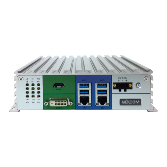
Page 18: Knowing Your Nise 106
LEd Indicators dVI-d LAN1 and LAN2 Power Button Used to connect the system to a local area network. Power Button Press to power-on or power-off the system. Copyright © 2015 NEXCOM International Co., Ltd. All Rights Reserved. NISE 106 User Manual... -
Page 19: Rear Panel
DisplayPort to connect the system with display devices. Fieldbus Expansion slot for add-on fieldbus modules. Remote On/Off Used to connect a remote to power on/off the system. Fieldbus COM3 COM4 Remote On/Off Copyright © 2015 NEXCOM International Co., Ltd. All Rights Reserved. NISE 106 User Manual... -
Page 20: Mechanical Dimensions
Chapter 1: Product Introduction Mechanical dimensions 184.85 Copyright © 2015 NEXCOM International Co., Ltd. All Rights Reserved. NISE 106 User Manual... -
Page 21: Chapter 2: Jumpers And Connectors
Static electricity can damage many of the electronic ▪ Use correct screws and do not over tighten screws. components. Humid environments tend to have less static electricity than Copyright © 2015 NEXCOM International Co., Ltd. All Rights Reserved. NISE 106 User Manual... -
Page 22: Jumper Settings
(on) and open (off). Two-Pin Jumpers: Open (Left) and Short (Right) Three-Pin Jumpers: Pins 1 and 2 are Short Copyright © 2015 NEXCOM International Co., Ltd. All Rights Reserved. NISE 106 User Manual... -
Page 23: Locations Of The Jumpers And Connectors For Nisb 106
Locations of the Jumpers and Connectors for NISB 106 NISB 106 The figure below is the top view of the NISB 106 main board which is the main board used in NISE 106. It shows the locations of the jumpers and connectors. COM1/COM3 COM2/COM4... -
Page 24: Jumpers And Dip Switches
1-2 On ATX Mode 2-3 On ATX Mode 2-3 On AT Reset 2-3 On: default 1-2 On: default definition definition AT_PWRBT# PBT_TR PMU_PWRBTN# PBT_SW ATX_PWRBT# PM_RESET#_J Copyright © 2015 NEXCOM International Co., Ltd. All Rights Reserved. NISE 106 User Manual... -
Page 25: Clear Cmos
Connector type: 2x2 DIP switch Connector location: SW1 Connector location: SW2 Settings definition 1-2 On Normal 2-3 On Clear BIOS Setting OS_GPIO_SUS10 1-2 On: default OS_GPIO_SUS11 definition SRTCRST# RTEST# Copyright © 2015 NEXCOM International Co., Ltd. All Rights Reserved. NISE 106 User Manual... -
Page 26: Connector Pin Definitions
Power Button Connector type: Phoenix Contact 1x3 3-pin terminal block Connector location: SW3 Connector location: PW1 definition definition definition PBT_SW VIN_2 PBT_SW VIN_VSS PWR_SW_P PWR_SW_N VIN_GND Copyright © 2015 NEXCOM International Co., Ltd. All Rights Reserved. NISE 106 User Manual... -
Page 27: Usb 3.0 Ports (Usb3/4) And Lan2
USB_2N V1P5_LAN2 LAN2_MDI0P USB_2P LAN2_MDI0N LAN2_MDI1P USB3_RXN2 USB3_RXP2 LAN2_MDI1N LAN2_MDI2P USB3_TXN2 LAN2_MDI2N LAN2_MDI3P USB3_TXP2 5VSB LAN2_MDI3N USB_3N USB_3P LAN2_LINK1G# LAN2_LINK100# USB3_RXN3 LAN2_LED_ACT# 3VSB USB3_RXP3 USB3_TXN3 USB3_TXP3 Copyright © 2015 NEXCOM International Co., Ltd. All Rights Reserved. NISE 106 User Manual... -
Page 28: Usb 3.0 Ports (Usb1/2) And Lan1
USB_0N V1P5_LAN LAN1_MDI0P USB_0P LAN1_MDI0N LAN1_MDI1P USB3_RXN0 USB3_RXP0 LAN1_MDI1N LAN1_MDI2P USB3_TXN0 LAN1_MDI2N LAN1_MDI3P USB3_TXP0 5VSB LAN1_MDI3N USB_1N USB_1P LAN1_LINK1G# LAN1_LINK100# USB3_RXN1 LAN1_LED_ACT# 3VSB USB3_RXP1 USB3_TXN1 USB3_TXP1 Copyright © 2015 NEXCOM International Co., Ltd. All Rights Reserved. NISE 106 User Manual... -
Page 29: Hdmi
HDMI_TX2P_C DVI_DATA2_N_C DVI_DATA2_P_C HDMI_TX2N_C HDMI_TX1P_C HDMI_TX1N_C DVI_CTRL_CLK HDMI_TX0P_C DVI_CTRL_DAT HDMI_TX0N_C HDMI_CLK_P_C DVI_DATA1_N_C DVI_DATA1_P_C HDMI_CLK_N_C VCC5 HDMI_CTRL_CLK HDMI_CTRL_DAT DVI_HPD_C VCC5 DVI_DATA0_N_C DVI_DATA0_P_C HDMI_HPD FRONT_GND FRONT_GND DVI_CLK_P_C DVI_CLK_N_C Copyright © 2015 NEXCOM International Co., Ltd. All Rights Reserved. NISE 106 User Manual... -
Page 30: Led Indicators
VCC5 COM3_TXLEDN VCC5 COM3_RXLEDN LEd1 VCC5 COM4_TXLEDN VCC5 COM4_RXLEDN VCC5 COM1_TXLEDN VCC5 COM1_RXLEDN LEd2 VCC5 COM2_TXLEDN VCC5 COM2_RXLEDN VCC5 PWR_LED_N VCC3 HDD_LED_N LEd3 BAT_LED_N VCC5 GPO_PR0 Copyright © 2015 NEXCOM International Co., Ltd. All Rights Reserved. NISE 106 User Manual... -
Page 31: External I/O Interfaces - Rear Panel
SATA_TXP0 UIM_PWR UIM_RESET SATA_TXN0 UIM_CLK SATA_RXN0 SATA_RXP0 UIM_VPP UIM_DATA CFAST_LED1_C CFAST_ACCESS PC10 PC11 PC12 PC13 VCC3 PC14 VCC3 PC15 PC16 PC17 CFAST_CDO_C Copyright © 2015 NEXCOM International Co., Ltd. All Rights Reserved. NISE 106 User Manual... -
Page 32: Com 1 Port (Rs232/422/485)
SP2_DSR SP2_RTS- SP1_RTS SP1_RTS+ SP2_RTS SP2_RTS+ SP1_CTS SP1_CTS+ SP2_CTS SP2_CTS+ SP1_RI SP1_CTS- SP2_RI SP2_CTS- REAR_GND REAR_GND REAR_GND REAR_GND REAR_GND REAR_GND REAR_GND REAR_GND REAR_GND REAR_GND REAR_GND REAR_GND Copyright © 2015 NEXCOM International Co., Ltd. All Rights Reserved. NISE 106 User Manual... -
Page 33: Com 3 And Com 4 Ports (Rs232)
SP3_TXD SP3_DTR SP3_DSR DDI1TXP2_C DDI1TXN1_C SP3_RTS SP3_CTS SP3_RI DDI1TXP1_C DDI1TXN0_C DDI1TXP0_C COM4 DDI1_AUXP_C DDI1_AUXN_C DP_HPD_C definition definition VCC3 SP4_DCD SP4_RXD SP4_TXD SP4_DTR SP4_DSR SP4_RTS SP4_CTS SP4_RI Copyright © 2015 NEXCOM International Co., Ltd. All Rights Reserved. NISE 106 User Manual... -
Page 34: Remote Sw/Remote S3 Connector
Chapter 2: Jumpers and Connectors Remote SW/Remote S3 Connector Connector type: 4-pin terminal block Connector location: JP1 definition definition PBT_TR REMOTE_S3 Copyright © 2015 NEXCOM International Co., Ltd. All Rights Reserved. NISE 106 User Manual... -
Page 35: Internal Connectors
Connector type: Standard Serial ATA 7P (1.27mm, SATA-M-180) Connector type: 1x2 2-pin header, 2.5mm pitch Connector location: CN2 Connector location: J1 definition definition definition SATA_TXP1 VCC5 SATA_TXN1 SATA_RXN1 SATA_RXP1 Copyright © 2015 NEXCOM International Co., Ltd. All Rights Reserved. NISE 106 User Manual... -
Page 36: Fan Connector
Connector type: 1x2 2-pin header, 2.54mm pitch Connector type: 1x6 6-pin header, 1mm pitch Connector location: CN3 Connector location: J3 definition definition definition 3VSB VCC12 COM3_TXD COM3_RXD VCC3 Copyright © 2015 NEXCOM International Co., Ltd. All Rights Reserved. NISE 106 User Manual... -
Page 37: Cmos Battery Connector
Connector type: 1x10 10-pin header, 1.0mm pitch Connector location: J7 Connector location: J6 definition definition definition definition VRTC_BAT PLTRST_3P3# LPC_CLK0_DEBUG LPC_FRAME# LPC_AD3 LPC_AD2 LPC_AD1 LPC_AD0 VCC3 VCC3 Copyright © 2015 NEXCOM International Co., Ltd. All Rights Reserved. NISE 106 User Manual... -
Page 38: Flash Bios
Connector location: JFW1 Connector location: JP8 definition definition definition definition PWR_LED_N POWER_LED_PWR V1P8A SPI0_CS# SPI0_CLK HDD_LED_N HDD_LED_PWR SMB_3P3_CLK SMB_3P3_DAT SPI0_MISO SPI0_MOSI 3VSB SLP_S3_3P3# PS_ON PBT_TR PMU_RSTBTN# Copyright © 2015 NEXCOM International Co., Ltd. All Rights Reserved. NISE 106 User Manual... -
Page 39: Reset Button Connector
Connector type: 2x5 10-pin header, 2.00mm pitch Connector location: JP9 Connector location: JP7 definition definition definition VCC5 LPC_WDT# ICH_GPO0_OUT ICH_GPI0_IN ICH_GPO1_OUT ICH_GPI1_IN ICH_GPO2_OUT ICH_GPI2_IN ICH_GPO3_OUT ICH_GPI3_IN Copyright © 2015 NEXCOM International Co., Ltd. All Rights Reserved. NISE 106 User Manual... -
Page 40: Line-Out Pin Header
Connector type: 1x4 4-pin header, 2.0mm pitch Connector type: 1x4 4-pin header, 2.0mm pitch Connector location: JP4 Connector location: JP5 definition definition LOUT_R3 MIC1_R3 EXLINEOUT_JD MIC1_JD LINE_GND MIC_GND LOUT_L3 MIC1_L3 Copyright © 2015 NEXCOM International Co., Ltd. All Rights Reserved. NISE 106 User Manual... -
Page 41: Line-In Pin Header
Connector type: 1x4 4-pin header, 2.0mm pitch Connector type: 1x5 5-pin header, 2.0mm pitch Connector location: JP6 Connector location: J2 definition definition definition FLIN_L VCC5 SP2_RI_T LIN_JD VCC12 SP2_RI_T LIN_GND SP2_RI FLIN_R Copyright © 2015 NEXCOM International Co., Ltd. All Rights Reserved. NISE 106 User Manual... -
Page 42: Gsm Mini-Pcie Earout Pin Header
Connector type: 1x2 2-pin header, 2.0mm pitch Connector type: 1x2 2-pin header, 2.0mm pitch Connector location: JP3 Connector location: JP2 definition definition EAROUTN MICINP EAROUTP MICINN Copyright © 2015 NEXCOM International Co., Ltd. All Rights Reserved. NISE 106 User Manual... -
Page 43: Mini-Pcie Connector (3G/Wi-Fi)
PCIE_TXN2 SMB_3P3_DAT PCIE_CLKREQ#2 UIM_PWR PCIE_TXP2 UIM_DATA USB_4N PCIE_CLKN2 UIM_CLK USB_4P PCIE_CLKP2 UIM_RESET 3VSB_MINI1 UIM_VPP 3VSB_MINI1 3VSB_MINI1 MCLK PLTRST_3P3# PCMO V1P5S_MINI1 PCIE_RXN2 3VSB_MINI1 PCMI PCIE_RXP2 PCMSYNC 3VSB_MINI1 Copyright © 2015 NEXCOM International Co., Ltd. All Rights Reserved. NISE 106 User Manual... -
Page 44: Chapter 3: System Setup
1. Locate the 6 screws on the bottom side of the chassis cover. 2. Remove all the 6 screws on the bottom side of the chassis cover. Copyright © 2015 NEXCOM International Co., Ltd. All Rights Reserved. NISE 106 User Manual... - Page 45 Chapter 3: System Setup 3. Remove the chassis cover. Copyright © 2015 NEXCOM International Co., Ltd. All Rights Reserved. NISE 106 User Manual...
-
Page 46: Installing A So-Dimm Memory Module
3. Insert the SO-DIMM memory module into the socket and push the module down until a clicking sound is heard. bracket Memory module 2. Locate the SO-DIMM socket. Copyright © 2015 NEXCOM International Co., Ltd. All Rights Reserved. NISE 106 User Manual... -
Page 47: Installing A Wireless Lan Module (Half-Size)
1. Locate the mini-PCIe slot on the board. 3. Install the mini-PCIe bracket to the mini-PCIe module. Screw Mini-PCIe slot Mini-PCIe bracket 2. Remove the mini-PCIe bracket from the board. Copyright © 2015 NEXCOM International Co., Ltd. All Rights Reserved. NISE 106 User Manual... - Page 48 5. Push the module down and secure it with the screws. until the gold-plated connector on the edge of the module completely disappears into the slot. Copyright © 2015 NEXCOM International Co., Ltd. All Rights Reserved. NISE 106 User Manual...
-
Page 49: Installing A Wireless Lan Module (Full-Size)
2. Insert the mini-PCIe module into the mini-PCIe slot at 45 degree angle until the gold-plated connector on the edge of the module completely disappears into the slot. Mini-PCIe slot Mini-PCIe bracket Copyright © 2015 NEXCOM International Co., Ltd. All Rights Reserved. NISE 106 User Manual... - Page 50 Chapter 3: System Setup 3. Push the module down and secure it with the screws. Copyright © 2015 NEXCOM International Co., Ltd. All Rights Reserved. NISE 106 User Manual...
-
Page 51: Installing A Sim Card
1. Remove the CFast/SIM card cover. 2. Insert the SIM card into the SIM card slot. 3. Close the cover and secure it to the original position. Copyright © 2015 NEXCOM International Co., Ltd. All Rights Reserved. NISE 106 User Manual... -
Page 52: Installing A Sata Hard Drive
1. Locate the internal HDD bracket and remove all the 3 screws on the 2. Place the 2.5" HDD into the internal HDD bracket then use the screws to bracket. secure the 2.5" HDD in place. Copyright © 2015 NEXCOM International Co., Ltd. All Rights Reserved. NISE 106 User Manual... - Page 53 Chapter 3: System Setup 3. Place the internal HDD bracket back to its original position and secure it with screws. Copyright © 2015 NEXCOM International Co., Ltd. All Rights Reserved. NISE 106 User Manual...
-
Page 54: Installing A Cfast Card
1. Remove the CFast/SIM card cover. 2. Insert the CFast card into the CFast slot. 3. Close the cover and secure it to the original position. Copyright © 2015 NEXCOM International Co., Ltd. All Rights Reserved. NISE 106 User Manual... -
Page 55: Packing
Chapter 3: System Setup Packing NISE 106 plastic bag and EPE reference. Front View of Packing Rear View of Packing Copyright © 2015 NEXCOM International Co., Ltd. All Rights Reserved. NISE 106 User Manual... - Page 56 Chapter 3: System Setup Top View of Packing Bottom View of Packing Copyright © 2015 NEXCOM International Co., Ltd. All Rights Reserved. NISE 106 User Manual...
-
Page 57: Chapter 4: Bios Setup
This chapter describes how to use the BIOS setup program for the NISE 106. The The settings made in the setup program affect how the computer performs. BIOS screens provided in this chapter are for reference only and may change if It is important, therefore, first to try to understand all the setup options, and the BIOS is updated in the future. -
Page 58: Default Configuration
Powering on the computer and immediately pressing <Del> allows you to enter Setup. Load optimized default values. Press the key to enter Setup: Saves and exits the Setup program. Press <Enter> to enter the highlighted sub-menu Copyright © 2015 NEXCOM International Co., Ltd. All Rights Reserved. NISE 106 User Manual... - Page 59 When “” appears on the left of a particular field, it indicates that a submenu which contains additional options are available for that field. To display the submenu, move the highlight to that field and press Copyright © 2015 NEXCOM International Co., Ltd. All Rights Reserved. NISE 106 User Manual...
-
Page 60: Bios Setup Utility
F3: Optimized Defaults TXE FW Version 02.00.00.2056 F4: Save & Exit ESC: Exit System Date [Mon 11/09/2015] System Time [13:37:26] Version 2.17.1249. Copyright (C) 2015 American Megatrends, Inc. Copyright © 2015 NEXCOM International Co., Ltd. All Rights Reserved. NISE 106 User Manual... -
Page 61: Advanced
Select the highest ACPI sleep state the system will enter when the suspend Version 2.17.1249. Copyright (C) 2015 American Megatrends, Inc. button is pressed. The options are Suspend Disabled and S3 (Suspend to RAM). Copyright © 2015 NEXCOM International Co., Ltd. All Rights Reserved. NISE 106 User Manual... - Page 62 Displays the Super I/O chip used on the board. Enables or disables the serial port. Onboard Serial Port Mode Select this to change the serial port mode to RS232, RS422, RS485 or RS485 Auto. Copyright © 2015 NEXCOM International Co., Ltd. All Rights Reserved. NISE 106 User Manual...
- Page 63 Select this to change the serial port mode to RS232, RS422, RS485 or RS485 Select this to change the serial port mode to RS232 or GPS Auto. Copyright © 2015 NEXCOM International Co., Ltd. All Rights Reserved. NISE 106 User Manual...
- Page 64 Version 2.17.1249. Copyright (C) 2015 American Megatrends, Inc. Version 2.17.1249. Copyright (C) 2015 American Megatrends, Inc. Serial Port Enables or disables the serial port. EIST Enables or disables Intel ® SpeedStep. Copyright © 2015 NEXCOM International Co., Ltd. All Rights Reserved. NISE 106 User Manual...
- Page 65 CPU Temperature(dTS) Detects and displays the current CPU temperature. System Temperature Detects and displays the current system temperature. VCore Detects and displays the Vcore CPU voltage. Copyright © 2015 NEXCOM International Co., Ltd. All Rights Reserved. NISE 106 User Manual...
- Page 66 Windows, this problem may occur. To avoid this problem, enable this field to limit the return value to 3 or lesser than 3. Intel ® Virtualization Technology Enables or disables Intel ® Virtualization technology. Copyright © 2015 NEXCOM International Co., Ltd. All Rights Reserved. NISE 106 User Manual...
- Page 67 Enables or disables SATA port 0 and port 1. Controls the execution of UEFI and legacy PXE OpROM. Onboard LAN PXE Enables or disables onboard LAN PXE ROM. Copyright © 2015 NEXCOM International Co., Ltd. All Rights Reserved. NISE 106 User Manual...
- Page 68 Disable Keeps USB devices available only for EFI applications. XHCI Hand-off This is a workaround for OSs that does not support XHCI hand-off. The XHCI ownership change should be claimed by the XHCI driver. Copyright © 2015 NEXCOM International Co., Ltd. All Rights Reserved. NISE 106 User Manual...
-
Page 69: Chipset
Version 2.17.1249. Copyright (C) 2015 American Megatrends, Inc. WWAN digital Voice Interface Configures the interface for WWAN digital voice. South Bridge Enters the South Bridge submenu. Copyright © 2015 NEXCOM International Co., Ltd. All Rights Reserved. NISE 106 User Manual... - Page 70 F4: Save & Exit ESC: Exit Version 2.17.1249. Copyright (C) 2015 American Megatrends, Inc. USB Power State in S5 Configures the USB power state in S5. Copyright © 2015 NEXCOM International Co., Ltd. All Rights Reserved. NISE 106 User Manual...
- Page 71 Enables or disables BIOS lock enable (BLE) feature. Azalia HdMI Codec Global SMI Lock Enables or disables internal HDMI codec for Azalia. Enables or disables global SMI lock. Copyright © 2015 NEXCOM International Co., Ltd. All Rights Reserved. NISE 106 User Manual...
- Page 72 PCI Express Port 1 to PCI Express Port 3 Configures the operation mode of the XHCI controller. Enables or disables the PCI Express ports 1 to 3 on the chipset. Copyright © 2015 NEXCOM International Co., Ltd. All Rights Reserved. NISE 106 User Manual...
-
Page 73: Security
Adjust the boot sequence of the system. Boot Option #1 is the first boot device that the system will boot from, next will be #2 and so forth. Copyright © 2015 NEXCOM International Co., Ltd. All Rights Reserved. NISE 106 User Manual... -
Page 74: Save & Exit
<Enter>. You may be prompted to confirm again before exiting. Restore defaults To restore the BIOS to default settings, select this field then press <Enter>. A dialog box will appear. Confirm by selecting Yes. Copyright © 2015 NEXCOM International Co., Ltd. All Rights Reserved. NISE 106 User Manual... -
Page 75: Appendix A: Power Consumption
Laboratory DC Power Supply GWINSTEK GPC-60300 Add-on Card CPU Cooler NISE 106 CPU Heatsink SHYUNG SHUHN System FAN Keyboard Microsoft Wired Keyboard 600 Mouse Microsoft Basic Optical Mouse Monitor ASUS VS228 Copyright © 2015 NEXCOM International Co., Ltd. All Rights Reserved. NISE 106 User Manual... - Page 76 3. Measure the power consumption and record it. 4. Run Burn-in test program to apply 100% full loading. 5. Measure the power consumption and record it. Copyright © 2015 NEXCOM International Co., Ltd. All Rights Reserved. NISE 106 User Manual...
-
Page 77: Appendix B: Led Programming Guide
B: L PPendIx rogrammIng uIde LEDs are provided for custom system design. This appendix provides definitions and its default setting for the LEDs in the NISE 106 series. The LED definition is shown in the following table: PowerOn Address default... -
Page 78: Appendix C: Watchdog Timer Setting
WDT_SET); outportb(SUPERIO_PORT+1, 0x90); # Use the second # Use the minute, change value to 0x10 # Set WDT sec/min outportb(SUPERIO_PORT, WDT_VALUE); outportb(SUPERIO_PORT+1, 0x05); #Set 5 seconds Copyright © 2015 NEXCOM International Co., Ltd. All Rights Reserved. NISE 106 User Manual... -
Page 79: Appendix D: Gpi/O Programming Guide
GPI/O (General Purpose Input/Output) pins are provided for custom system design. This appendix provides definitions and its default setting for the ten GPI/O pins in the NISE 106 series. The pin definition is shown in the following table: PowerOn... - Page 80 #define GPO1_LO outportb(0xA02, 0x00) #define GPO2_HI outportb(0xA07, GPO2) #define GPO2_LO outportb(0xA07, 0x00) #define GPO3_HI outportb(0xA07, GPO3) #define GPO3_LO outportb(0xA07, 0x00) void main(void) GPO0_HI; GPO1_LO; GPO2_HI; GPO3_LO; Copyright © 2015 NEXCOM International Co., Ltd. All Rights Reserved. NISE 106 User Manual...
Need help?
Do you have a question about the NISE 106 and is the answer not in the manual?
Questions and answers