
Related Manuals for Nexcom NISE 108


Summary of Contents for Nexcom NISE 108
- Page 1 NEXCOM International Co., Ltd. IoT Automation Solutions Business Group Fan-less Computer NISE 108 User Manual NEXCOM International Co., Ltd. www.nexcom.com Published March 2020...
-
Page 2: Table Of Contents
Internal Connectors ................17 Knowing Your NISE 108 ................4 Debug Connector ................17 Front Panel ..................4 LED Connector ................17 Rear Panel ...................4 LVDS Connector ................18 Mechanical Dimensions ................5 Copyright © 2020 NEXCOM International Co., Ltd. All Rights Reserved. NISE 108 User Manual... - Page 3 About BIOS Setup .................36 When to Configure the BIOS ..............36 Default Configuration ................37 Entering Setup ..................37 Legends ....................37 BIOS Setup Utility ..................39 Main ....................39 Advanced ..................40 Copyright © 2020 NEXCOM International Co., Ltd. All Rights Reserved. NISE 108 User Manual...
-
Page 4: Preface
Acknowledgements The product(s) described in this manual complies with all applicable NISE 108 is a trademark of NEXCOM International Co., Ltd. All other product European Union (CE) directives if it has a CE marking. For computer systems names mentioned herein are registered trademarks of their respective to remain CE compliant, only CE-compliant parts may be used. -
Page 5: Rohs Compliance
(Cr6+) < 0.1% or 1,000ppm, Polybrominated biphenyls (PBB) < 0.1% or 1,000ppm, and Polybrominated diphenyl Ethers (PBDE) < 0.1% or 1,000ppm. In order to meet the RoHS compliant directives, NEXCOM has established an engineering and manufacturing task force to implement the introduction of green products. -
Page 6: Warranty And Rma
“NEXCOM RMA Service Form” for the RMA number apply process. ▪ If RMA goods can not be repaired, NEXCOM will return it to the customer without any charge. ▪ Customers can send back the faulty products with or without accessories (manuals, cable, etc.) and any components from the card, such as CPU... - Page 7 ESD workstation. If no such station is available, you can provide some ESD protection by wearing an antistatic wrist strap and attaching it to a metal part of the computer chassis. Copyright © 2020 NEXCOM International Co., Ltd. All Rights Reserved. NISE 108 User Manual...
-
Page 8: Safety Information
Danger of explosion if battery is incorrectly replaced. Replace with the same or equivalent type recommended by CAUTION! CAUTION! CAUTION! the manufacturer. Discard used batteries according to the manufacturer’s instructions. viii Copyright © 2020 NEXCOM International Co., Ltd. All Rights Reserved. NISE 108 User Manual... -
Page 9: Safety Precautions
REPLACED. REPLACE ONLY WITH THE SAME OR EQUIVALENT TYPE 10. All cautions and warnings on the equipment should be noted. RECOMMENDED BY THE MANUFACTURER. DISCARD USED BATTERIES ACCORDING TO THE MANUFACTURER’S INSTRUCTIONS. Copyright © 2020 NEXCOM International Co., Ltd. All Rights Reserved. NISE 108 User Manual... -
Page 10: Technical Support And Assistance
Preface Technical Support and Assistance Conventions Used in this Manual 1. For the most updated information of NEXCOM products, visit NEXCOM’s Warning: website at www.nexcom.com. Information about certain situations, which if not observed, can cause personal injury. This will prevent injury to yourself 2. -
Page 11: Global Service Contact Information
16F, No.250, Sec. 2, Chongde Rd., Beijing, 100094, China Beitun Dist., Tel: +86-10-5704-2680 Taichung City 406, R.O.C. Fax: +86-10-5704-2681 Tel: +886-4-2249-1179 Email: sales@nexcom.cn Fax: +886-4-2249-1172 www.nexcom.cn Email: sales@nexcom.com.tw www.nexcom.com.tw Copyright © 2020 NEXCOM International Co., Ltd. All Rights Reserved. NISE 108 User Manual... - Page 12 Tokyo, 108-0014, Japan No. 609, Yunlin East Rd., Tel: +81-3-5419-7830 Shanghai, 200062, China Fax: +81-3-5419-7832 Tel: +86-21-5278-5868 Email: sales@nexcom-jp.com Fax: +86-21-3251-6358 www.nexcom-jp.com Email: renwang@nexcom.com.tw www.nexcom.cn Copyright © 2020 NEXCOM International Co., Ltd. All Rights Reserved. NISE 108 User Manual...
-
Page 13: Package Contents
Preface Package Contents Before continuing, verify that the NISE 108 package that you received is complete. Your package should have all the items listed in the following table. Item Part Number Name description 4NCPF00309X00 Terminal Blocks 3P Phoenix Contact:1827716 3.81mm Female DIP Green... -
Page 14: Ordering Information
Preface Ordering Information The following information below provides ordering information for NISE 108. NISE 108 (P/N: 10J00010800X0) Intel Celeron processor J3455 quad core, 1.50GHz fanless system ® ® • 24V, 60W AC/dC power adapter w/o power cord (P/N: 7400060032X00) Copyright © 2020 NEXCOM International Co., Ltd. All Rights Reserved. -
Page 15: Chapter 1: Product Introduction
▪ 3 x COM ports (COM3 with RS232/422/485, jumper-free setting) ▪ Support both 2.5” HDD and M.2 ▪ Support -5~55 degree C operating temperature ▪ Support 24 VDC input Copyright © 2020 NEXCOM International Co., Ltd. All Rights Reserved. NISE 108 User Manual... -
Page 16: Hardware Specifications
– HDD: 20G, half sine, 11ms, IEC60068-2-27 I/O Interface - Rear – CFast: 50G, half sine, 11ms, IEC60068-2-27 ▪ 1 x Antenna hole for optional Wi-Fi/3.5G antenna Copyright © 2020 NEXCOM International Co., Ltd. All Rights Reserved. NISE 108 User Manual... - Page 17 – Sinusoidal: 2Grms @ 5~500 Hz, IEC60068-2-6 Certifications ▪ CE ▪ FCC Class A OS Support List ▪ Windows 10 IoT Enterprise, 64-bit ▪ Linux kernel version 4.1 Copyright © 2020 NEXCOM International Co., Ltd. All Rights Reserved. NISE 108 User Manual...
-
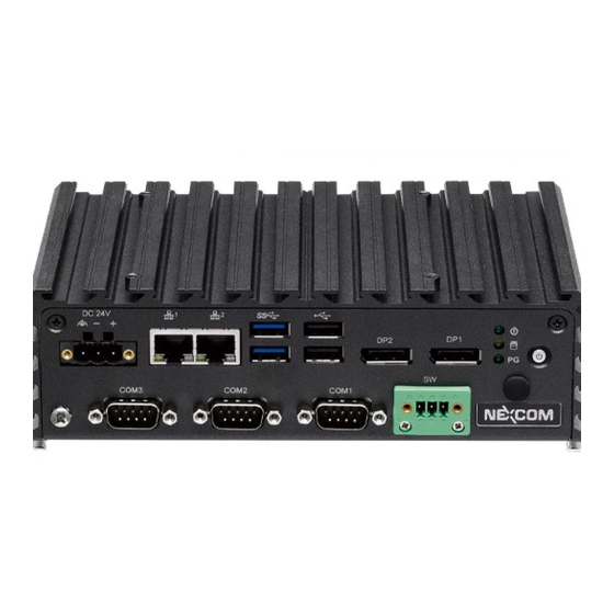
Page 18: Knowing Your Nise 108
Used to connect a remote to power on/off the system. Antenna Hole The external antenna mounting holes are used to mount and connect optional Wi-Fi antennas. Antenna Hole Copyright © 2020 NEXCOM International Co., Ltd. All Rights Reserved. NISE 108 User Manual... -
Page 19: Mechanical Dimensions
Chapter 1: Product Introduction Mechanical dimensions 184.85 206.00 Copyright © 2020 NEXCOM International Co., Ltd. All Rights Reserved. NISE 108 User Manual... -
Page 20: Chapter 2: Jumpers And Connectors
Static electricity can damage many of the electronic ▪ Use correct screws and do not over tighten screws. components. Humid environments tend to have less static electricity than Copyright © 2020 NEXCOM International Co., Ltd. All Rights Reserved. NISE 108 User Manual... -
Page 21: Jumper Settings
(on) and open (off). Two-Pin Jumpers: Open (Left) and Short (Right) Three-Pin Jumpers: Pins 1 and 2 are Short Copyright © 2020 NEXCOM International Co., Ltd. All Rights Reserved. NISE 108 User Manual... -
Page 22: Locations Of The Jumpers And Connectors For Nisb 108
Locations of the Jumpers and Connectors for NISB 108 NISB 108 The following figures are the top and bottom view of the NISB 108 main board which is the main board used in NISE 108. It shows the locations of the jumpers and connectors. Top View CLR_CMOS1... - Page 23 Chapter 2: Jumpers and Connectors GPIO1 WLED1 W_USB1 COM1 FRONT1 Bottom View COM2 REM_BT1 TOUCH1 JCOM2_RI1 COM3 JPWR_MODE1 SATA1 JPNL_PWR1 MPCIE1 NGFF1 JBLT_PWM1 CONNECTOR LVDS2 LVDS1 INV1 Copyright © 2020 NEXCOM International Co., Ltd. All Rights Reserved. NISE 108 User Manual...
-
Page 24: Jumpers
Connector type: 1x3 3-pin header, 2.54mm pitch Connector type: 1x3 3-pin header, 2.54mm pitch Connector location: JPNL_PWR1 Connector location: JBLT_PWM1 Settings Settings 1-2 On +3V3 1-2 On +3V3 2-3 On 2-3 On Copyright © 2020 NEXCOM International Co., Ltd. All Rights Reserved. NISE 108 User Manual... -
Page 25: Clear Cmos
Connector type: 1x3 3-pin header, 2.54mm pitch Connector location: CLR_CMOS1 and CLR_CMOS2 Connector location: JPWR_MODE1 Settings Settings 1-2 On Normal 1-2 On 2-3 On Clear 2-3 On Copyright © 2020 NEXCOM International Co., Ltd. All Rights Reserved. NISE 108 User Manual... -
Page 26: Com2 Port Power Setting
Chapter 2: Jumpers and Connectors COM2 Port Power Setting Connector type: 2x3 6-pin header, 2.0mm pitch Connector location: JCOM2_RI1 Settings 1-2 On +12V 3-4 On Ring 5-6 On Copyright © 2020 NEXCOM International Co., Ltd. All Rights Reserved. NISE 108 User Manual... -
Page 27: Connector Pin Definitions
GPIO LED (Green, user defined) LANE0_P SATA LED (Yellow) LANE0_N LANE1_P Power LED (Green) LANE1_N LANE2_P LANE2_N LANE3_P LANE3_N CONFIG1 CONFIG2 AUX_P AUX_N DP_RETURN DP_PWR Copyright © 2020 NEXCOM International Co., Ltd. All Rights Reserved. NISE 108 User Manual... -
Page 28: Usb 2.0 Ports
Connector location: USB2 Connector location: USB1 definition definition definition definition USB_2N_C USB_0N_C USB_2P_C USB_0P_C USB_3N_C USB3_RX0_N_C USB3_RX0_P_C USB_3P_C USB3_TX0_N_C USB3_TX0_P_C USB_1N_C USB_1P_C USB3_RX1_N_C USB3_RX1_P_C USB3_TX1_N_C USB3_TX1_P_C Copyright © 2020 NEXCOM International Co., Ltd. All Rights Reserved. NISE 108 User Manual... -
Page 29: Lan1 Port
10Mbps or no link 10Mbps or no link definition definition definition definition MDI_PLUS0 MDI_MINUS0 MDI_PLUS0 MDI_MINUS0 MDI_PLUS1 MDI_MINUS1 MDI_PLUS1 MDI_MINUS1 MDI_PLUS2 MDI_MINUS2 MDI_PLUS2 MDI_MINUS2 MDI_PLUS3 MDI_MINUS3 MDI_PLUS3 MDI_MINUS3 Copyright © 2020 NEXCOM International Co., Ltd. All Rights Reserved. NISE 108 User Manual... -
Page 30: 24V Dc Power Input
Chapter 2: Jumpers and Connectors 24V dC Power Input Connector type: Phoenix Contact 1x3 3-pin terminal block Connector location: DC24V_IN1 definition +24V CHASSIS GND Copyright © 2020 NEXCOM International Co., Ltd. All Rights Reserved. NISE 108 User Manual... -
Page 31: Internal Connectors
Connector type: 1x5 5-pin header, 2.0mm pitch Connector location: DB1 Connector location: WLED1 definition definition definition definition LPC_PLTRST# HDD_LED- HDD_LED+ LPC_CLK LPC_LFRAME# STBY_LED+ LPC_LAD3 LPC_LAD2 POWER_LED+ LPC_LAD1 LPC_LAD0 LPC_SERIRQ +3.3V Copyright © 2020 NEXCOM International Co., Ltd. All Rights Reserved. NISE 108 User Manual... -
Page 32: Lvds Connector
+VCC_LCD LVDSB_LDC4P LVDSA_LDC3P LVDSA_LDC0N LVDSB_LDC7P LVDSB_LDC4N LVDSA_LDC3N +VCC_LCD LVDSB_LDC7N +VCC_LCD LVDSA_LDC1P LVDSB_LDC5P LVDSA_LL1CP LVDSA_LDC1N LVDSB_LL2CP LVDSB_LDC5N LVDSA_LL1CN LVDSB_LL2CN +V_INV +V_INV LVDSA_LDC2P +V_INV LVDSB_LDC6P +V_INV LVDSA_LDC2N LVDSB_LDC6P Copyright © 2020 NEXCOM International Co., Ltd. All Rights Reserved. NISE 108 User Manual... -
Page 33: Lvds Inverter Connector
Connector location: INV1 Connector location: FRONT1 definition definition definition definition +12V PWR_LED# PWR_LED +12V BKCTRL HDD_LED# HDD_LED MAIN_SMBCLK +3V3 BKLEN MAIN_SMBDATA SLP_S3# PS_ON PWR_BTN# RST _BTN# Copyright © 2020 NEXCOM International Co., Ltd. All Rights Reserved. NISE 108 User Manual... -
Page 34: Internal Usb 2.0 Connector
Connector type: 1x6 6-pin header, 2.5mm pitch Connector type: 1x5 5-pin header, 2.5mm pitch Connector location: W_USB1 Connector location: TOUCH1 definition definition definition definition USB_4N_C USB_4P_C Sense Copyright © 2020 NEXCOM International Co., Ltd. All Rights Reserved. NISE 108 User Manual... -
Page 35: Remote On/Off Connector
Connector location: REM_BT1 Connector location: GPIO1 definition definition definition REMOTE_S3 GPO_0 GPI_0 REMOTE_ PWRBT# GPO_1 GPI_1 GPO_2 GPI_2 GPO_3 GPI_3 GPO_4 GPI_4 GPO_5 GPI_5 GPO_6 GPI_6 GPO_7 GPI_7 Copyright © 2020 NEXCOM International Co., Ltd. All Rights Reserved. NISE 108 User Manual... -
Page 36: Com3 Connector (Rs232/422/485)
Connector location: COM1 and COM2 definition definition definition definition DCD# / TX- RXD / TX+ DCD# TXD / RX+ DTR# / RX- DTR# DSR# DSR# RTS# CTS# RTS# CTS# Copyright © 2020 NEXCOM International Co., Ltd. All Rights Reserved. NISE 108 User Manual... -
Page 37: Sata Connector (7-Pin And 15-Pin)
Connector type: 1x2 2-pin header, 1.25mm pitch Connector location: SATA1 Connector location: J1 definition definition definition SATA1_TXP SATA1_TXN SATA1_RXN SATA1_RXP VCC3 VCC3 VCC3 VCC5 VCC5 VCC5 VCC5 VCC12 VCC12 VCC12 Copyright © 2020 NEXCOM International Co., Ltd. All Rights Reserved. NISE 108 User Manual... -
Page 38: Mini-Pcie Connector
3.3VSB_4 GND8 GND5 UIM_VPP 3.3VSB_5 LED_WWAN# REV10/UIM_C8 GND11 GND14 LED_WLAN# REV9/UIM_C4 W_DISABLE# REV4 LED_WPAN# GND4 PERST# REV3 1.5V_1 PERn0 3.3VSB_1 REV2 GND7 PERp0 GND10 REV1 3.3VSB_2 Copyright © 2020 NEXCOM International Co., Ltd. All Rights Reserved. NISE 108 User Manual... -
Page 39: Connector (B-Key)
COEX1 PERn1/USB3.0-Rx-/SSIC-RxN UIM-RESET ANTC TL3 SIM_DETECT PERp1/USB3.0-Rx+/SSIC-RxP UIM-CLK RESET# SUSCLK (32KhZ) GND4 UIM-DATA CONFIG_1 3.3V_3 PETn1/USB3.0-Tx-/SSIC-TxN UIM-PWR GND9 3.3V_4 PETn1/USB3.0-Tx+/SSIC-TxP DEVSLP GND10 3.3V_5 GND5 GPIO_0 CONFIG_2 Copyright © 2020 NEXCOM International Co., Ltd. All Rights Reserved. NISE 108 User Manual... -
Page 40: Chapter 3: System Setup
1. Locate the six mounting screws from the bottom cover. 3. With the screws removed, lift up the cover and remove it from the chassis. Copyright © 2020 NEXCOM International Co., Ltd. All Rights Reserved. NISE 108 User Manual... -
Page 41: Installing A So-Dimm Memory Module
The ejector tabs at the ends of the socket will automatically snap into the locked position to hold the module in place. SO-dIMM Socket Memory Module Copyright © 2020 NEXCOM International Co., Ltd. All Rights Reserved. NISE 108 User Manual... - Page 42 Chapter 3: System Setup 3. Push the module down until the clips on both sides of the socket lock into position. Copyright © 2020 NEXCOM International Co., Ltd. All Rights Reserved. NISE 108 User Manual...
-
Page 43: Installing A Wireless Lan Module (Half-Size)
Installing a Wireless LAN Module (Half-size) 1. Locate the mini-PCIe slot on the board. 2. Install the mini-PCIe bracket to the mini-PCIe module. Screw Mini-PCIe Slot Copyright © 2020 NEXCOM International Co., Ltd. All Rights Reserved. NISE 108 User Manual... - Page 44 4. Push the module down and secure it with a screw. until the gold-plated connector on the edge of the module completely disappears into the slot. WLAN Module Copyright © 2020 NEXCOM International Co., Ltd. All Rights Reserved. NISE 108 User Manual...
-
Page 45: Installing An M.2 Storage Module (2242)
2. Make sure the gold-plated six-pin connector on the edge of the module is on the left, while the five-pin connector is on the right. Six-Pin Five-Pin M.2 B-Key Slot Copyright © 2020 NEXCOM International Co., Ltd. All Rights Reserved. NISE 108 User Manual... - Page 46 4. Push the module down and secure it with a screw. gold-plated connector on the edge of the module completely disappears into the slot. M.2 Module Screw Copyright © 2020 NEXCOM International Co., Ltd. All Rights Reserved. NISE 108 User Manual...
-
Page 47: Installing A Sata Storage Drive
2. Place the 2.5" storage drive into the internal storage bracket then use the the storage bracket. screws to secure the 2.5" storage drive in place. Copyright © 2020 NEXCOM International Co., Ltd. All Rights Reserved. NISE 108 User Manual... - Page 48 3. Place the internal storage bracket back to its original position. Before 4. Secure the internal storage bracket with screws. securing the bracket with screws, make sure the washers are aligned on top of the mounting holes. Copyright © 2020 NEXCOM International Co., Ltd. All Rights Reserved. NISE 108 User Manual...
-
Page 49: Wall Mounting Instructions
Wall Mount Bracket Fasten screws to mount Specification of the wall mount screw: the system to the wall Round Head Screw Long Fei:P6#32Tx 1/4/SW7*0.8 w/Spring+Flat Washer Copyright © 2020 NEXCOM International Co., Ltd. All Rights Reserved. NISE 108 User Manual... -
Page 50: Chapter 4: Bios Setup
This chapter describes how to use the BIOS setup program for NISE 108. The The settings made in the setup program affect how the computer performs. BIOS screens provided in this chapter are for reference only and may change It is important, therefore, first to try to understand all the setup options, and if the BIOS is updated in the future. -
Page 51: Default Configuration
Powering on the computer and immediately pressing <Del> allows you to enter Setup. Load optimized default values. Press the key to enter Setup: Saves and exits the Setup program. Press <Enter> to enter the highlighted sub-menu Copyright © 2020 NEXCOM International Co., Ltd. All Rights Reserved. NISE 108 User Manual... - Page 52 When “” appears on the left of a particular field, it indicates that a submenu which contains additional options are available for that field. To display the submenu, move the highlight to that field and press Copyright © 2020 NEXCOM International Co., Ltd. All Rights Reserved. NISE 108 User Manual...
-
Page 53: Bios Setup Utility
F2: Previous Values System Date [Fri 11/29/2019] F3: Optimized Defaults System Time [16:14:43] F4: Save & Exit ESC: Exit Version 2.18.1263. Copyright (C) 2019 American Megatrends, Inc. Copyright © 2020 NEXCOM International Co., Ltd. All Rights Reserved. NISE 108 User Manual... -
Page 54: Advanced
Select the highest ACPI sleep state the system will enter when the suspend button is pressed. The options are Suspend Disabled and S3 (Suspend to Version 2.18.1263. Copyright (C) 2019 American Megatrends, Inc. RAM). Copyright © 2020 NEXCOM International Co., Ltd. All Rights Reserved. NISE 108 User Manual... - Page 55 Version 2.18.1263. Copyright (C) 2019 American Megatrends, Inc. Serial Port Super IO Chip Enables or disables the serial port. Displays the Super I/O chip used on the board. Copyright © 2020 NEXCOM International Co., Ltd. All Rights Reserved. NISE 108 User Manual...
- Page 56 Enables or disables the serial port. Onboard Serial Port Mode Select this to change the serial port mode to RS232, RS422 or RS485. Terminal Resistor Enables or disables the terminal resistor. Copyright © 2020 NEXCOM International Co., Ltd. All Rights Reserved. NISE 108 User Manual...
- Page 57 Detects and displays the current system temperature. hardware capabilities provided by Vanderpool Technology. VCore to VCC3 VT-d Detects and displays the output voltages. Enables or disables VT-d function on MCH. Copyright © 2020 NEXCOM International Co., Ltd. All Rights Reserved. NISE 108 User Manual...
- Page 58 F4: Save & Exit ESC: Exit Version 2.18.1263. Copyright (C) 2019 American Megatrends, Inc. Version 2.18.1263. Copyright (C) 2019 American Megatrends, Inc. EIST Enables or disables Intel SpeedStep. ® Copyright © 2020 NEXCOM International Co., Ltd. All Rights Reserved. NISE 108 User Manual...
- Page 59 ESC: Exit Version 2.18.1263. Copyright (C) 2019 American Megatrends, Inc. Version 2.18.1263. Copyright (C) 2019 American Megatrends, Inc. Network Stack Enables or disables UEFI network stack. Copyright © 2020 NEXCOM International Co., Ltd. All Rights Reserved. NISE 108 User Manual...
- Page 60 Security device Support Enables or disables BIOS support for security device. O.S will not show Security Device. TCG EFI protocol and INT1A interface will not be available. Copyright © 2020 NEXCOM International Co., Ltd. All Rights Reserved. NISE 108 User Manual...
- Page 61 XHCI ownership change should be claimed by the XHCI driver. USB Mass Storage driver Support Enables or disables USB mass storage driver support. USB transfer time-out The time-out value for control, bulk, and Interrupt transfers. Copyright © 2020 NEXCOM International Co., Ltd. All Rights Reserved. NISE 108 User Manual...
-
Page 62: Chipset
Version 2.18.1263. Copyright (C) 2019 American Megatrends, Inc. SMBus Support Enables or disables SMBus support. Version 2.18.1263. Copyright (C) 2019 American Megatrends, Inc. Setting incorrect field values may cause the system to malfunction. Copyright © 2020 NEXCOM International Co., Ltd. All Rights Reserved. NISE 108 User Manual... - Page 63 ESC: Exit Version 2.18.1263. Copyright (C) 2019 American Megatrends, Inc. Version 2.18.1263. Copyright (C) 2019 American Megatrends, Inc. Hd-Audio Support Enables or disables HD Audio support. Copyright © 2020 NEXCOM International Co., Ltd. All Rights Reserved. NISE 108 User Manual...
- Page 64 OS. Please do not disable it unless for debugging purposes. Port 0 Enables or disables SATA port 0. Port 1 Enables or disables SATA port 1. Copyright © 2020 NEXCOM International Co., Ltd. All Rights Reserved. NISE 108 User Manual...
-
Page 65: Security
Select this to reconfigure the user’s password. (G3 state). USB Power State in S5 Configures the USB power state in S5 for USB0/1, USB2/3 and USB4. Copyright © 2020 NEXCOM International Co., Ltd. All Rights Reserved. NISE 108 User Manual... -
Page 66: Boot
When set to Off, the function of the numeric keypad is the arrow keys Quiet Boot Enabled Displays OEM logo instead of the POST messages. Disabled Displays normal POST messages. Copyright © 2020 NEXCOM International Co., Ltd. All Rights Reserved. NISE 108 User Manual... -
Page 67: Save & Exit
Restore defaults To restore the BIOS to default settings, select this field then press <Enter>. A dialog box will appear. Confirm by selecting Yes. Copyright © 2020 NEXCOM International Co., Ltd. All Rights Reserved. NISE 108 User Manual... -
Page 68: Appendix A: Power Consumption
3. Measure the power consumption and record it. 4. Run burn-in test program and apply 100% full loading. 5. Measure the power consumption and record it. Copyright © 2020 NEXCOM International Co., Ltd. All Rights Reserved. NISE 108 User Manual... -
Page 69: Appendix B: Gpi/O Programming Guide
GPI/O (General Purpose Input/Output) pins are provided for custom system design. This appendix provides definitions and its default setting for the ten GPI/O pins in NISE 108. The pin definition is shown in the following table: PowerOn GPI/O Mode... -
Page 70: Appendix C: Led Programming Guide
Appendix C: LED Programming Guide C: L PPendIx roGrammInG uIde LEDs are provided for custom system design. This appendix provides definitions and its default setting for the LEDs in NISE 108. The LED definition is shown in the following table: PowerOn Address default LED1-C3...
Need help?
Do you have a question about the NISE 108 and is the answer not in the manual?
Questions and answers