
Related Manuals for Nexcom nTUF 600


Summary of Contents for Nexcom nTUF 600
- Page 1 NEXCOM International Co., Ltd. Industrial Computing Solutions Fan-less Computer nTUF 600 User Manual NEXCOM International Co., Ltd. www.nexcom.com Published January 2013...
-
Page 2: Table Of Contents
Knowing Your nTUF 600 .................4 LAN1/LAN2 Link/Active LEDs ............16 Front Panel ..................4 Power LEDs ..................17 Rear Panel ...................6 External I/O Interfaces - Rear Panel.............18 Mechanical Dimensions ................7 Copyright © 2012 NEXCOM International Co., Ltd. All Rights Reserved. nTUF 600 User Manual... - Page 3 Locations of the Jumpers and Connectors for ICES253-600 ....33 ICES253-600 - Top ................33 Appendix B: GPI/O Programming Guide....84 ICES253-600 - Bottom ...............34 Connector Pin Definitions ..............35 Appendix C: Watchdog Timer Setting....86 Internal Connectors ................35 Copyright © 2012 NEXCOM International Co., Ltd. All Rights Reserved. nTUF 600 User Manual...
-
Page 4: Preface
No describes how to keep the system CE compliant. part of this manual may be reproduced, copied, translated or transmitted in any form or by any means without the prior written consent from NEXCOM Declaration of Conformity International Co., Ltd. -
Page 5: Rohs Compliance
(Cr6+) < 0.1% or 1,000ppm, Polybrominated biphenyls (PBB) < 0.1% or 1,000ppm, and Polybrominated diphenyl Ethers (PBDE) < 0.1% or 1,000ppm. In order to meet the RoHS compliant directives, NEXCOM has established an engineering and manufacturing task force to implement the introduction of green products. -
Page 6: Warranty And Rma
(manuals, cable, etc.) and any components from the card, such as CPU and RAM. If the components were suspected as part of the problems, ▪ If RMA goods can not be repaired, NEXCOM will return it to the customer please note clearly which components are included. Otherwise, NEXCOM without any charge. - Page 7 ESD workstation. If no such station is available, you can provide some ESD protection by wearing an antistatic wrist strap and attaching it to a metal part of the computer chassis. Copyright © 2012 NEXCOM International Co., Ltd. All Rights Reserved. nTUF 600 User Manual...
-
Page 8: Safety Information
There is a danger of explosion if battery is incorrectly replaced. Replace only with the same or equivalent type recommended by the manufacturer. Discard used batteries according to the manufacturer’s instructions. viii Copyright © 2012 NEXCOM International Co., Ltd. All Rights Reserved. nTUF 600 User Manual... -
Page 9: Safety Precautions
RECOMMENDED BY THE MANUFACTURER. DISCARD USED BATTERIES ACCORDING TO THE MANUFACTURER’S INSTRUCTIONS. 10. All cautions and warnings on the equipment should be noted. Copyright © 2012 NEXCOM International Co., Ltd. All Rights Reserved. nTUF 600 User Manual... -
Page 10: Technical Support And Assistance
Preface Technical Support and Assistance Conventions Used in this Manual 1. For the most updated information of NEXCOM products, visit NEXCOM’s Warning: website at www.nexcom.com. Information about certain situations, which if not observed, can cause personal injury. This will prevent injury to yourself 2. -
Page 11: Global Service Contact Information
Chongde Rd., Beitun Dist., Shanghai, 200062, China Fax: +86-27-8722-7400 Taichung City 406, R.O.C. Tel: +86-21-6150-8008 Email: sales@nexcom.cn Tel: +886-4-2249-1179 Fax: +86-21-3251-6358 www.nexcom.cn Fax: +886-4-2249-1172 Email: sales@nexcom.cn www.nexcom.com.tw www.nexcom.cn Copyright © 2012 NEXCOM International Co., Ltd. All Rights Reserved. nTUF 600 User Manual... -
Page 12: United Kingdom
Fax: +33 (0) 1 40 90 31 01 Email: sales.uk@nexcom.eu Email: sales.fr@nexcom.eu www.nexcom.eu www.nexcom.eu Germany NEXCOM GmbH Leopoldstraße Business Centre, Leopoldstraße 244, 80807 Munich, Germany Tel: +49-89-208039-278 Fax: +49-89-208039-279 Email: sales.de@nexcom.eu www.nexcom.eu Copyright © 2012 NEXCOM International Co., Ltd. All Rights Reserved. nTUF 600 User Manual... -
Page 13: Package Contents
Preface Package Contents Before continuing, verify that the nTUF 600 package that you received is complete. Your package should have all the items listed in the following table. Item Part Number Description 602DCD0477X00 (N)nTUF600 DVD DRIVER VER:1.0 60177A0263X00 (N)nROB600 QUICK REFERENCE GUIDE VER:A... -
Page 14: Ordering Information
Preface Ordering Information The following information below provides ordering information for nTUF 600 series. • Barebone nTUF 600 (P/N: 10M00060000X2) - Intel® Atom™ Dual Core D525 1.8GHz Fanless Marine Computer nTUF 605 (P/N: 10M00060500X0) - Intel® Atom™ Dual Core D525 1.8GHz Marine Computer with DVD Combo Copyright ©... -
Page 15: Chapter 1: Product Introduction
▪ Dual cold swappable 2.5” SSD tray ▪ 2x RS232 ▪ Supports ATX Power Mode, WoL, LAN Teaming and PXE function ▪ 2x PS/2 for keyboard and mouse Copyright © 2012 NEXCOM International Co., Ltd. All Rights Reserved. nTUF 600 User Manual... -
Page 16: Hardware Specifications
▪ 294mm (W) x 200mm (D) x 100mm (H) (11.6”x 7.9”x 3.94”) ▪ 1x external screwed type CFast socket ▪ 3-pin +24V DC input Construction ▪ 1x external fuse;10A ▪ Aluminum chassis with fanless design Copyright © 2012 NEXCOM International Co., Ltd. All Rights Reserved. nTUF 600 User Manual... - Page 17 (Based on IEC60945 4th edition, IACS E10 and DNV 2.4) ▪ Storage temperature: -30°C ~ 80°C ▪ Relative humidity: 10% to 93% (non-condensing) Certifications ▪ IEC60945 ▪ IACS E10 ▪ DNV 2.4 Copyright © 2012 NEXCOM International Co., Ltd. All Rights Reserved. nTUF 600 User Manual...
-
Page 18: Knowing Your Ntuf 600
Line-out jack to connect speakers or headphones. Fuse CFast socket Line-in HDD Tray M12 LAN port Line-in jack for audio input. 4 USB2.0 ports to connect the system with USB2.0/1.1 device. Copyright © 2012 NEXCOM International Co., Ltd. All Rights Reserved. nTUF 600 User Manual... - Page 19 Used to insert a CFast card. Power/HDD/LAN LED Indicates the power status, hard drive and LAN activity of the system. Power Switch Press to power-on or power-off the system. Copyright © 2012 NEXCOM International Co., Ltd. All Rights Reserved. nTUF 600 User Manual...
-
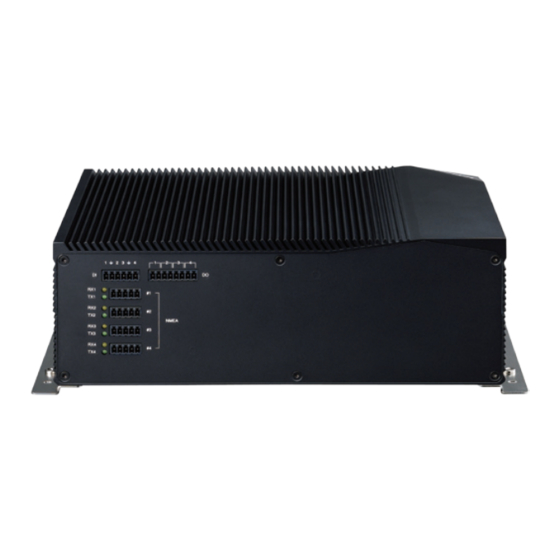
Page 20: Rear Panel
Four NMEA interfaces used to connect NMEA 0183 RS422 serial devices. (Please set the mode to RS485 in the BIOS menu if RS485 connection is used.) NMEA 0183 interface Copyright © 2012 NEXCOM International Co., Ltd. All Rights Reserved. nTUF 600 User Manual... -
Page 21: Mechanical Dimensions
Chapter 1: Product Introduction Mechanical Dimensions Copyright © 2012 NEXCOM International Co., Ltd. All Rights Reserved. nTUF 600 User Manual... -
Page 22: Chapter 2: Jumpers And Connectors
Static electricity can damage many of the electronic ▪ Use correct screws and do not over tighten screws. components. Humid environments tend to have less static electricity than Copyright © 2012 NEXCOM International Co., Ltd. All Rights Reserved. nTUF 600 User Manual... -
Page 23: Jumper Settings
(on) and open (off). Two-Pin Jumpers: Open (Left) and Short (Right) Three-Pin Jumpers: Pins 1 and 2 are Short Copyright © 2012 NEXCOM International Co., Ltd. All Rights Reserved. nTUF 600 User Manual... -
Page 24: Locations Of The Jumpers And Connectors For Nrom600
Locations of the Jumpers and Connectors for nROM600 nROB600 The figure below shows the location of the jumpers and connectors. J2 JP1 IDE1 USB1 CN6A/CN6B COM1A/COM1B LAN1 LAN2 Copyright © 2012 NEXCOM International Co., Ltd. All Rights Reserved. nTUF 600 User Manual... -
Page 25: Jumpers
Connector location: JP2 Connector location: J10 Settings Settings 1-2 On Normal 1-2 On 3.3V 2-3 On Clear BIOS 2-3 On 1-2 On: default 1-2 On: default Copyright © 2012 NEXCOM International Co., Ltd. All Rights Reserved. nTUF 600 User Manual... -
Page 26: Connector Pin Definitions
External I/O Interfaces - Front Panel Connector location: KM1 24V DC Input Connector type: 3-pin terminal block PS/2 Mouse PS/2 Keyboard Definition Definition Definition KB DATA KBMSVCC KBCLK MDATA KBMSVCC MCLK Copyright © 2012 NEXCOM International Co., Ltd. All Rights Reserved. nTUF 600 User Manual... -
Page 27: Com 5 And Com 6 Ports
HDMI2_DATA2_P SP1_TXD SP1_DTR HDMI2_DATA2_N HDMI2_DATA1_P SP1_DSR HDMI2_DATA1_N SP1_RTS SP1_CTS HDMI2_DATA0_P SP1_RI SP2_DCD HDMI2_DATA0_N HDMI2_CLK_P SP2_RXD SP2_TXD HDMI2_CLK_N SP2_DTR HDMI2_CTRL_CLK HDMI2_CTRL_DATA SP2_DSR SP2_RTS HDMI2_VCC5 SP2_CTS SP2_RI HDMI2_HPD_R Copyright © 2012 NEXCOM International Co., Ltd. All Rights Reserved. nTUF 600 User Manual... -
Page 28: Dvi & Vga Connector
TX2+ 2048*1536 2048*1536 2048*1536 1920*1200 DDC_CLK HDMI 1920*1200 DDC_DATA TX1- TX1+ nTUF 2048*1536 2048*1536 2048*1536 DVI_VCC(+5V) 1920*1200 1920*1200 1920*1200 HotPlugDet TX0- TX0+ HDMI 1920*1200 TXCLK+ TXCLK- Copyright © 2012 NEXCOM International Co., Ltd. All Rights Reserved. nTUF 600 User Manual... -
Page 29: Lan 1 Connector
Connector location: LAN1 Connector location: LAN2 Definition Definition Definition Definition LAN1M1P LAN1M3P LAN2M1P LAN2M3P LAN1M3N LAN1M0N LAN2M3N LAN2M0N LAN1M2P LAN1M0P LAN2M2P LAN2M0P LAN1M1N LAN1M2N LAN2M1N LAN2M2N Copyright © 2012 NEXCOM International Co., Ltd. All Rights Reserved. nTUF 600 User Manual... -
Page 30: Quadruple Usb Port
Off: 10M Green (L1) (L2) Green: GbE Active Active Yellow Bottom Blinking: Activity is occurring (A1) (A2) Definition Definition USB_3N USB_3P USB2N USN2P USB1N USB1P USB0N USB0P Copyright © 2012 NEXCOM International Co., Ltd. All Rights Reserved. nTUF 600 User Manual... -
Page 31: Power Leds
Chapter 2: Jumpers and Connectors Power LEDs Connector location: LED3 Status LED Color Green Yellow Copyright © 2012 NEXCOM International Co., Ltd. All Rights Reserved. nTUF 600 User Manual... -
Page 32: External I/O Interfaces - Rear Panel
Connector type: 8-pin switch Connector type: 6-pin switch Connector location: CN6 Connector location: CN1 Definition Definition GPI3_R RELAY3_OUT RELAY3_IN GPI2_R RELAY2_OUT GPI1_R RELAY2_IN RELAY1_OUT GPI0_R RELAY1_IN RELAY0_OUT RELAY0_IN Copyright © 2012 NEXCOM International Co., Ltd. All Rights Reserved. nTUF 600 User Manual... -
Page 33: Nmea Port 1
Connector type: 5-pin switch Connector location: CN2 Connector location: CN3 Definition Definition RS422_RX3+ RS422_RX4+ RS422_RX3- RS422_RX4- ISO_GND ISO_GND RS422_TX3+ RS422_TX4+ RS485_D3+ RS485_D4+ RS422_TX3- RS422_TX4- RS485_D3- RS485_D4- Copyright © 2012 NEXCOM International Co., Ltd. All Rights Reserved. nTUF 600 User Manual... -
Page 34: Nmea Port 3
Connector type: 5-pin switch Connector location: CN4 Connector location: CN5 Definition Definition RS422_RX5+ RS422_RX6+ RS422_RX5- RS422_RX6- ISO_GND ISO_GND RS422_TX5+ RS422_TX6+ RS485_D5+ RS485_D6+ RS422_TX5- RS422_TX6- RS485_D5- RS485_D6- Copyright © 2012 NEXCOM International Co., Ltd. All Rights Reserved. nTUF 600 User Manual... -
Page 35: Internal Connectors
Connector type: 1x4 4-pin header, 2.54mm pitch Connector type: 1x4 4-pin header, 2.54mm pitch Connector location: J5 Connector location: J6 Definition Definition +12V +12V CPUFANIN SYSFANIN CPUFANOUT SYSFANOUT Copyright © 2012 NEXCOM International Co., Ltd. All Rights Reserved. nTUF 600 User Manual... -
Page 36: System Fan Connector
Connector type: 1x7 JST, 7-pin header, 2.5mm pitch Connector location: J11 Connector location: J9 Definition Definition Definition V_INV(+12V) +12V Panel Backlight V_INV(+12V) Brightness Control Panel Backlight Enable Copyright © 2012 NEXCOM International Co., Ltd. All Rights Reserved. nTUF 600 User Manual... -
Page 37: Lvds Connector
VCC_LCD LVDSB_DATA0 LVDSA_DATA3 LVDSA_DATA0# LVDSB_DATA3 LVDSB_DATA0# LVDSA_DATA3# VCC_LCD LVDSB_DATA3# VCC_LCD LVDSA_DATA1 LVDSB_DATA1 LVDSA_CLK LVDSA_DATA1# LVDSB_CLK LVDSB_DATA1# LVDSA_CLK# LVDSB_CLK# V_INV(+12V) V_INV(+12V) LVDSA_DATA2 V_INV(+12V) LVDSB_DATA2 V_INV(+12V) LVDSA_DATA2# LVDSB_DATA2# Copyright © 2012 NEXCOM International Co., Ltd. All Rights Reserved. nTUF 600 User Manual... -
Page 38: Usb Connector
Connector type: 1x6 JST, 6-pin header, 2.00mm pitch Connector type: 1x4 4-pin header, 2.00mm pitch Connector location: JP4 Connector location: J7 Definition Definition Definition USB4N FLOUT_L LOUT_JD USB4P USB5N USB5P FLOUT_R Copyright © 2012 NEXCOM International Co., Ltd. All Rights Reserved. nTUF 600 User Manual... -
Page 39: Mic-In Pin Header
Connector type: 1x4 4-pin header, 2.00mm pitch Connector type: 1x4 4-pin header, 2.00mm pitch Connector location: JP3 Connector location: JP5 Definition Definition MIC_L FLIN_L MIC_JD LIN_JD MIC_R FLIN_R Copyright © 2012 NEXCOM International Co., Ltd. All Rights Reserved. nTUF 600 User Manual... -
Page 40: Power Connector
Connector type: Standard Serial ATAII 7P (1.27mm, SATA-M-180) Connector location: CN4 Connector location: J3 Definition Definition Definition Definition +12VSB +12VSB SATA_TXP0 +12VSB POWER_STATUS SATA_TXN0 SATA_RXN0 SATA_RXP0 Copyright © 2012 NEXCOM International Co., Ltd. All Rights Reserved. nTUF 600 User Manual... -
Page 41: Sata2 Connector
Connector type: Standard Serial ATAII 7P (1.27mm, SATA-M-180) Connector type: 1x2 2-pin header, 2.5mm pitch Connector location: J4 Connector location: J1 Definition Definition Definition SATA_TXP1 SATA_TXN1 SATA_RXN1 SATA_RXP1 Copyright © 2012 NEXCOM International Co., Ltd. All Rights Reserved. nTUF 600 User Manual... -
Page 42: Sata Power Connector
Connector location: J2 Connector location: CN7 Definition S7 PC1 PC17 Definition Definition SATA_TXP2 SATA_TXN2 CFAST_ACCESS SATA_RXN2 PC10 SATA_RXP2 PC11 PC12 PC13 +3.3V PC14 +3.3V PC15 PC16 PC17 Copyright © 2012 NEXCOM International Co., Ltd. All Rights Reserved. nTUF 600 User Manual... -
Page 43: Mini-Pcie Connector
Definition Definition PCIEWAKE# +3VSB +1.5V SMBCLK +1.5V PCIETX0- SMBDATA CLKREQ# PCIETX0+ USB_D- REF CLK- USB_D+ REF CLK+ +3VSB +3VSB Disable# RST# +1.5V PCIERX0- +3VSB PCIERX0+ +3VSB Copyright © 2012 NEXCOM International Co., Ltd. All Rights Reserved. nTUF 600 User Manual... -
Page 44: Sim Card Connector
Connector location: IDE1 Connector type: 1x6 6-pin header, 1.00mm pitch Connector location: J16 Definition Definition Definition Definition UIM_PWR UIM_RESET +3VSB UIM_CLK COM6_TXD COM6_RXD UIM_VPP UIM_DATA +3.3V Copyright © 2012 NEXCOM International Co., Ltd. All Rights Reserved. nTUF 600 User Manual... -
Page 45: Box Header Connector
Signal Signal COM1_485_EN# COM2_TXD GPO2 COM1_RTS# COM2_RXD GPI2 COM2_485_EN# COM3_TXD GPO3 COM2_RTS# COM3_RXD GPI3 COM3_485_EN# COM4_TXD COM3_RTS# COM4_RXD COM4_485_EN# COM4_RTS# GPO0 GPI0 COM1_TXD GPO1 COM1_RXD GPI1 Copyright © 2012 NEXCOM International Co., Ltd. All Rights Reserved. nTUF 600 User Manual... -
Page 46: Pwr_Bt/Ret_Bt/Led/Sm Bus Pin Header
PWR_BT/RET_BT/LED/SM BUS Pin Header Connector type: 2x17 34-pin header, 2.00mm pitch Connector location: JP1 Definition Definition PWR_LED_N PWR_LED_P SATA_LED# SATA_LED_P SMB_C SMB_D VCC3V3 PM_SLP_S3 PSON POWER BOTTOM RESET BOTTOM Copyright © 2012 NEXCOM International Co., Ltd. All Rights Reserved. nTUF 600 User Manual... -
Page 47: Locations Of The Jumpers And Connectors For Ices253-600
Chapter 2: Jumpers and Connectors Locations of the Jumpers and Connectors for ICES253-600 ICES253-600 - Top The figure below shows the location of the jumpers and connectors. FAN1 Copyright © 2012 NEXCOM International Co., Ltd. All Rights Reserved. nTUF 600 User Manual... -
Page 48: Ices253-600 - Bottom
Chapter 2: Jumpers and Connectors ICES253-600 - Bottom The figure below shows the location of the jumpers and connectors. Copyright © 2012 NEXCOM International Co., Ltd. All Rights Reserved. nTUF 600 User Manual... -
Page 49: Connector Pin Definitions
GBE0_LINK# LPC_DRQ0# SATA2_TX- GBE0_MDI1- LPC_DRQ1# SUS_S5# PWR_OK GBE0_MDI1+ LPC_CLK SATA2_RX+ SATA2_RX- GBE0_MDI0- PWRBTN# BATLOW# GBE0_MDI0+ SMB_CK ATA_ACT# AC_SDIN2 GBE0_CTREF SMB_DAT AC_SYNC AC_SDIN1 SUS_S3# SMB_ALERT# AC_RST# AC_SDIN0 Copyright © 2012 NEXCOM International Co., Ltd. All Rights Reserved. nTUF 600 User Manual... - Page 50 LVDS_A2+ EXCD0_CPPE# SYS_RESET# LVDS_VDD_EN LPC_SERIRQ CB_RESET# LVDS_BKLT_EN LVDS_A_CK+ GPI0 GPO1 LVDS_A_CK- PCIE_TX4+ PCIE_RX4+ LVDS_I2C_CK LVDS_BKLT_CTRL PCIE_TX4- PCIE_RX4- LVDS_I2C_DAT VCC_5V_SBY GPO2 GPI3 VCC_5V_SBY PCIE_TX3+ PCIE_RX3+ KBD_RST# VCC_5V_SBY Copyright © 2012 NEXCOM International Co., Ltd. All Rights Reserved. nTUF 600 User Manual...
- Page 51 A104 VCC_12V B104 VCC_12V A105 VCC_12V B105 VCC_12V A106 VCC_12V B106 VCC_12V A107 VCC_12V B107 VCC_12V A108 VCC_12V B108 VCC_12V A109 VCC_12V B109 VCC_12V A110 B110 Copyright © 2012 NEXCOM International Co., Ltd. All Rights Reserved. nTUF 600 User Manual...
-
Page 52: High Speed Board-To-Board Connector: Row C And D
PCI_AD2 PCI_AD7 IDE_D1 IDE_ACK# PCI_AD4 PCI_C/BE0# PCI_AD6 PCI_AD9 IDE_D14 IDE_IRQ PCI_AD8 PCI_AD11 IDE_IORDY IDE_A0 PCI_AD10 PCI_AD13 IDE_IOR# IDE_A1 PCI_AD12 PCI_AD15 PCI_PME# IDE_A2 PCI_GNT2# IDE_CS1# PCI_AD14 PCI_PAR Copyright © 2012 NEXCOM International Co., Ltd. All Rights Reserved. nTUF 600 User Manual... - Page 53 C104 VCC_12V D104 VCC_12V C105 VCC_12V D105 VCC_12V C106 VCC_12V D106 VCC_12V C107 VCC_12V D107 VCC_12V C108 VCC_12V D108 VCC_12V C109 VCC_12V D109 VCC_12V C110 D110 Copyright © 2012 NEXCOM International Co., Ltd. All Rights Reserved. nTUF 600 User Manual...
-
Page 54: Cpu Fan Connector
Chapter 2: Jumpers and Connectors CPU FAN Connector Connector type: 1x3 3-pin header, 2.54mm pitch Connector location: FAN1 Definition +12V FAN_SENSOR Copyright © 2012 NEXCOM International Co., Ltd. All Rights Reserved. nTUF 600 User Manual... -
Page 55: Chapter 3: System Setup
Before you stare, please kindly make sure that you have a torx screwdriver with you. Torx Screwdriver Copyright © 2012 NEXCOM International Co., Ltd. All Rights Reserved. nTUF 600 User Manual... - Page 56 3. Remove 3 screws on the top of the front panel and then put them in a safe place for later use. safe place for later use. 4. Lift up the cover and remove it from the chassis. Copyright © 2012 NEXCOM International Co., Ltd. All Rights Reserved. nTUF 600 User Manual...
-
Page 57: Installing The Sim Card
1. Slide the SIM card holder to the “OPEN” position and left the card holder. 2. Slide the SIM card into the SIM card holder. SIM card SIM card holder Copyright © 2012 NEXCOM International Co., Ltd. All Rights Reserved. nTUF 600 User Manual... - Page 58 Chapter 3: System Setup 3. Move the holder down and then slide it to the “LOCK” position. Copyright © 2012 NEXCOM International Co., Ltd. All Rights Reserved. nTUF 600 User Manual...
-
Page 59: Installing A Wireless Lan Module
2. Insert the wireless LAN module into the Mini PCI Express slot at a 45 degree angle until the gold-plated connector on the edge of the module completely disappears inside the slot. Mini PCI Express slot Wireless LAN module Copyright © 2012 NEXCOM International Co., Ltd. All Rights Reserved. nTUF 600 User Manual... - Page 60 Chapter 3: System Setup 3. Push the module down and then secure it with mounting screws. Mounting Screws Copyright © 2012 NEXCOM International Co., Ltd. All Rights Reserved. nTUF 600 User Manual...
-
Page 61: Installing A Wireless Lan Module (Bracket)
(Bracket) completely disappears inside the slot. Bracket Mounting Screws Mounting Screws 2. Push the module down and then secure it with mounting screws. Copyright © 2012 NEXCOM International Co., Ltd. All Rights Reserved. nTUF 600 User Manual... -
Page 62: Installing A Hard Drive
Installing a Hard Drive 1. Locate for the HDD tray in the front panel. Released HDD Tray HDD Tray 2. Loose both screws to release the HDD tray. Copyright © 2012 NEXCOM International Co., Ltd. All Rights Reserved. nTUF 600 User Manual... - Page 63 Chapter 3: System Setup 3. Use the provided screws to secure the drive in place. 4. Secure the HDD tray back to its original position. Copyright © 2012 NEXCOM International Co., Ltd. All Rights Reserved. nTUF 600 User Manual...
-
Page 64: Installing A Cfast Card
1. The CFast socket is located at the front side of the chassis. 3. Remove the socket’s cover to access the CFast socket. CFast socket 2. Remove the mounting screws of the CFast socket’s cover. Copyright © 2012 NEXCOM International Co., Ltd. All Rights Reserved. nTUF 600 User Manual... -
Page 65: Chapter 4: Bios Setup
Chapter 4: BIOS Setup Chapter 4: BIOS Setup This chapter describes how to use the BIOS setup program for the nTUF 600. The settings made in the setup program affect how the computer performs. The BIOS screens provided in this chapter are for reference only and may It is important, therefore, first to try to understand all the setup options, and change if the BIOS is updated in the future. -
Page 66: Default Configuration
POST: Press <Enter> to enter the highlighted sub¬menu Ctrl TO ENTER SETUP BEFORE BOOT PRESS Press the key to enter Setup: Copyright © 2012 NEXCOM International Co., Ltd. All Rights Reserved. nTUF 600 User Manual... - Page 67 When “” appears on the left of a particular field, it indicates that a submenu which contains additional options are available for that field. To display the submenu, move the highlight to that field and press Copyright © 2012 NEXCOM International Co., Ltd. All Rights Reserved. nTUF 600 User Manual...
-
Page 68: Bios Setup Utility
Select Item System Time [15:19:12] Change Field System Date [Fri 06/15/2012] Select Field General Help Save & Exit Exit v02.61 (C) Copyright 1985-2006, American Megatrends, Inc. Copyright © 2012 NEXCOM International Co., Ltd. All Rights Reserved. nTUF 600 User Manual... -
Page 69: Advanced
Hyper Threading Technology [Enabled] ↑↓ Select Item GPS Support [Disabled] Change Field Select Field General Help Save & Exit Exit v02.61 (C) Copyright 1985-2006, American Megatrends, Inc. Copyright © 2012 NEXCOM International Co., Ltd. All Rights Reserved. nTUF 600 User Manual... -
Page 70: Ide Configuration
This option configures the Serial ATA drives to use AHCI (Advanced Host Controller Interface). AHCI allows the storage driver to enable the advanced Serial ATA features which will increase storage performance. Copyright © 2012 NEXCOM International Co., Ltd. All Rights Reserved. nTUF 600 User Manual... -
Page 71: Primary Ide Master
Disables LBA mode Installed, Auto, CD/DVD and ARMD. Auto Enables LBA mode if the device supports it and the device is not already formatted with LBA mode disabled. Copyright © 2012 NEXCOM International Co., Ltd. All Rights Reserved. nTUF 600 User Manual... - Page 72 Selects the PIO mode. one sector at a time Auto The data transfer from and to the device occurs multiple sectors at a time if the device supports it Copyright © 2012 NEXCOM International Co., Ltd. All Rights Reserved. nTUF 600 User Manual...
- Page 73 (C) Copyright 1985-2006, American Megatrends, Inc. Selects the DMA mode. Enables, disables or automatically detect Self-Monitoring, Analysis and Reporting Technology. Auto Auto detected SWDMAn SingleWordDMAn MWDMAn MultiWordDMAn UDMAn UltraDMAn Copyright © 2012 NEXCOM International Co., Ltd. All Rights Reserved. nTUF 600 User Manual...
- Page 74 General Help DMA Mode Save & Exit S.M.A.R.T. [Auto] Exit 32Bit Data Transfer [Enabled] v02.61 (C) Copyright 1985-2006, American Megatrends, Inc. Enables or disables 32-bt data transfer. Copyright © 2012 NEXCOM International Co., Ltd. All Rights Reserved. nTUF 600 User Manual...
- Page 75 (C) Copyright 1985-2006, American Megatrends, Inc. v02.61 (C) Copyright 1985-2006, American Megatrends, Inc. Select the type of device connected to the system, the options are Not Installed, Auto, CD/DVD and ARMD. Copyright © 2012 NEXCOM International Co., Ltd. All Rights Reserved. nTUF 600 User Manual...
- Page 76 LBA Auto The data transfer from and to the device occurs mode disabled. multiple sectors at a time if the device supports it Copyright © 2012 NEXCOM International Co., Ltd. All Rights Reserved. nTUF 600 User Manual...
- Page 77 (C) Copyright 1985-2006, American Megatrends, Inc. v02.61 (C) Copyright 1985-2006, American Megatrends, Inc. Selects the PIO mode. Selects the DMA mode. Auto Auto detected SWDMAn SingleWordDMAn MWDMAn MultiWordDMAn UDMAn UltraDMAn Copyright © 2012 NEXCOM International Co., Ltd. All Rights Reserved. nTUF 600 User Manual...
- Page 78 (C) Copyright 1985-2006, American Megatrends, Inc. v02.61 (C) Copyright 1985-2006, American Megatrends, Inc. Enables, disables or automatically detect Self-Monitoring, Analysis Enables or disables 32-bt data transfer. and Reporting Technology. Copyright © 2012 NEXCOM International Co., Ltd. All Rights Reserved. nTUF 600 User Manual...
- Page 79 (C) Copyright 1985-2006, American Megatrends, Inc. v02.61 (C) Copyright 1985-2006, American Megatrends, Inc. Select the type of device connected to the system, the options are Not Installed, Auto, CD/DVD and ARMD. Copyright © 2012 NEXCOM International Co., Ltd. All Rights Reserved. nTUF 600 User Manual...
- Page 80 LBA Auto The data transfer from and to the device occurs mode disabled. multiple sectors at a time if the device supports it Copyright © 2012 NEXCOM International Co., Ltd. All Rights Reserved. nTUF 600 User Manual...
- Page 81 (C) Copyright 1985-2006, American Megatrends, Inc. v02.61 (C) Copyright 1985-2006, American Megatrends, Inc. Selects the PIO mode. Selects the DMA mode. Auto Auto detected SWDMAn SingleWordDMAn MWDMAn MultiWordDMAn UDMAn UltraDMAn Copyright © 2012 NEXCOM International Co., Ltd. All Rights Reserved. nTUF 600 User Manual...
- Page 82 (C) Copyright 1985-2006, American Megatrends, Inc. v02.61 (C) Copyright 1985-2006, American Megatrends, Inc. Enables, disables or automatically detect Self-Monitoring, Analysis Enables or disables 32-bt data transfer. and Reporting Technology. Copyright © 2012 NEXCOM International Co., Ltd. All Rights Reserved. nTUF 600 User Manual...
- Page 83 If a PS/2 keyboard is not available and you need to use a USB keyboard to install Windows (installation is performed in DOS mode) or run any program under DOS, set this field to Enabled. Copyright © 2012 NEXCOM International Co., Ltd. All Rights Reserved. nTUF 600 User Manual...
-
Page 84: Usb Mass Storage Device Configuration
Floppy and remaining as hard drive. Force FDD option can be used to force a HDD formatted drive to boot as FDD. Other available options are Floppy, Hard Disk and CD ROM. Copyright © 2012 NEXCOM International Co., Ltd. All Rights Reserved. nTUF 600 User Manual... -
Page 85: Acpi Configuration
Controller (APIC). Allows you to manually select an I/O address for the onboard serial port. Disabled Disables the onboard serial port.abled Disables the onboard serial port. Copyright © 2012 NEXCOM International Co., Ltd. All Rights Reserved. nTUF 600 User Manual... - Page 86 Serial Port6 Address [2E0] Serial Port6 IRQ [11] Serial Port6 IRQ [11] v02.61 (C) Copyright 1985-2006, American Megatrends, Inc. v02.61 (C) Copyright 1985-2006, American Megatrends, Inc. Copyright © 2012 NEXCOM International Co., Ltd. All Rights Reserved. nTUF 600 User Manual...
-
Page 87: Hardware Health Configuration
(C) Copyright 1985-2006, American Megatrends, Inc. CPU Temperature and System Temperature Detects and displays the current temperature of the CPU and the internal temperature of the system. Copyright © 2012 NEXCOM International Co., Ltd. All Rights Reserved. nTUF 600 User Manual... - Page 88 Detects and displays the Vcore CPU voltage. VIN0 (+12V) Detects and displays 12V voltage. VIN1 (+5V) Detects and displays 5V voltage. VIN2 (+3.3V) Detects and displays 3.3V voltage. Copyright © 2012 NEXCOM International Co., Ltd. All Rights Reserved. nTUF 600 User Manual...
-
Page 89: Boot
This section is used to select the boot priority sequence of the hard drives. Disabled Displays normal POST messages. Removable Drives This section is used to select the boot priority sequence of the removable drives. Copyright © 2012 NEXCOM International Co., Ltd. All Rights Reserved. nTUF 600 User Manual... - Page 90 Selects the drive to boot first, and second in the “1st Boot Device” and “2nd Boot Device” fields respectively. The BIOS will boot the operating system according to the sequence of the drive selected. Copyright © 2012 NEXCOM International Co., Ltd. All Rights Reserved. nTUF 600 User Manual...
-
Page 91: Chipset
DVMT Mode Select The options are Fixed mode and DVMT mode. DVMT/Fixed Memory This field is used to select the graphics memory size used by DVMT/Fixed mode. Copyright © 2012 NEXCOM International Co., Ltd. All Rights Reserved. nTUF 600 User Manual... -
Page 92: South Bridge Configuration
Enables or disables the mini PCIe controller. Enables or disables USB devices. USB 2.0 Controller This field is used to enable or disable the Enhanced Host Controller Interface (USB 2.0). Copyright © 2012 NEXCOM International Co., Ltd. All Rights Reserved. nTUF 600 User Manual... -
Page 93: Pcipnp
Configures Plug and Play (PnP) devices that are not required to boot in a Plug and Play supported operating system. The BIOS configures all the devices in the system. Copyright © 2012 NEXCOM International Co., Ltd. All Rights Reserved. nTUF 600 User Manual... -
Page 94: Security
3. Press <Enter> to confirm the new password. 4. When the Password Installed dialog box appears, select OK. To change the password, repeat the same steps above. Copyright © 2012 NEXCOM International Co., Ltd. All Rights Reserved. nTUF 600 User Manual... -
Page 95: Exit
To exit the Setup utility without saving the changes, select this field then press <Enter>. You may be prompted to confirm again before exiting. You can also press <ESC> to exit without saving the changes. Copyright © 2012 NEXCOM International Co., Ltd. All Rights Reserved. nTUF 600 User Manual... -
Page 96: Appendix A: Power Consumption
POWER ADAPTER FSP180-AAAN1 Add-on Card 3.5G module PCI-E Mini Card SIERRA WIRELESS:MC8790V CPU Cooler ICES 253 CPU HEATSINK System FAN Keyboard LEMEL B-5201-P Mouse GENIVS EASY MOUSE USB Copyright © 2012 NEXCOM International Co., Ltd. All Rights Reserved. nTUF 600 User Manual... - Page 97 3. Measure the power consumption and record it. 4. Run Burn-in test program to apply 100% full loading 5. Measure the power consumption and record it. Copyright © 2012 NEXCOM International Co., Ltd. All Rights Reserved. nTUF 600 User Manual...
-
Page 98: Appendix B: Gpi/O Programming Guide
284h (Bit2) GPO3 284h (Bit7) GPI3 High 284h (Bit3) Control the GPO pins level from I/O port 284h bit (4/5/6/7). The bit is Set/Clear indicated output High/Low Copyright © 2012 NEXCOM International Co., Ltd. All Rights Reserved. nTUF 600 User Manual... - Page 99 #define GPO5_LO outportb(GPIO_PORT, 0x00) #define GPO7_HI outportb(GPIO_PORT, 0x40) #define GPO7_LO outportb(GPIO_PORT, 0x00) #define GPO9_HI outportb(GPIO_PORT, 0x80) #define GPO9_LO outportb(GPIO_PORT, 0x00) void main(void) GPO3_HI; GPO5_LO; GPO7_HI; GPO9_LO; Copyright © 2012 NEXCOM International Co., Ltd. All Rights Reserved. nTUF 600 User Manual...
-
Page 100: Appendix C: Watchdog Timer Setting
# Use the Second to come down # If choose the Minute, change value to 0x40 # Set WDT sec/min outportb(SUPERIO_PORT, WDT_VALUE); outportb(SUPERIO_PORT+1 , 0x05); #Set 5 seconds Copyright © 2012 NEXCOM International Co., Ltd. All Rights Reserved. nTUF 600 User Manual...
Need help?
Do you have a question about the nTUF 600 and is the answer not in the manual?
Questions and answers