Table of Contents
Advertisement
Quick Links
Advertisement
Table of Contents

Related Manuals for Fayat Group DYNAPAC SD1800C


Summary of Contents for Fayat Group DYNAPAC SD1800C
- Page 1 BEDIENUNG & WARTUNG Straßenfertiger SD1800C Typ 911 02-0516 4812019403...
- Page 2 www.dynapac.com...
-
Page 3: Table Of Contents
Table of contents Preface ..................1 General safety instructions ................ 2 Laws, guidelines, accident prevention regulations ........2 Safety signs, signal words ................. 3 "Danger"! ....................3 "Warning" ! ..................... 3 "Caution" ! ....................3 "Note" ! ....................3 Other supplementary information ............... 3 Warnings .................... - Page 4 Identification points ...................17 Warning signs ...................20 Information signs ..................23 CE marking ....................25 Instructive symbols, prohibitive symbols, warning symbols .....26 Danger symbols ..................27 Further warnings and operating instructions ..........28 Identification label for the paver finisher (41) ........29 Explanation of 17PIN serial number ............30 Engine type plate ..................31 EN standards ....................32 Continuous sound pressure level .............32...
- Page 5 D23.18 Operating the display ............1 Operation of the input and display terminal ..........2 Button layout on the display ..............2 Menu operation - procedure for adjusting parameters ....... 4 Selecting and changing an adjustment parameter in a menu ....6 Selecting and changing a selection possibility in a menu ......
- Page 6 Windscreen wiper ...................9 Sunshade ....................9 Holder for the vandalism protection facility ..........9 Driver's seat, type I ................10 Driver's seat, type II ................11 Fuse box ....................12 Batteries ....................13 Main battery switch ................13 Hopper transport safeguard ..............14 Screed lock, mechanical ..............14 Paving thickness indicator ..............15 Auger lighting (o) ..................16 LED working light (o) ................17 Mechanical height adjustment, auger (o) ..........18...
- Page 7 Travel drive oil pressure indicator lamp (D) ......... 15 Preparation for transportation ..............17 Driving and stopping the paver finisher ..........19 Preparations for paving ................20 Separator fluid ..................20 Screed heater system ................20 Direction marks ..................21 Loading/conveying material ..............
- Page 8 F31.18 Maintenance - conveyor ............1 Maintenance - conveyor ................1 Maintenance intervals ................3 Points of maintenance ................4 Chain tension, conveyor (1) ..............4 Conveyor drive - drive chains (2) ............6 Conveyor deflectors / conveyor plates (3) ..........7 F40.18 Maintenance - auger assembly ..........1 Maintenance - auger assembly ..............1 Maintenance intervals ................3 Points of maintenance ................5...
- Page 9 F70.18 Maintenance - drive units ............1 Maintenance - drive units ................1 Maintenance intervals ................3 Points of maintenance ................6 Chain tension (1) ................... 6 Bottom plates (2) ................... 9 Rollers (3) .................... 10 Planetary gear (4) ................11 Screw connections ................
- Page 10 F100 Tests, stopping ................1 Tests, checks, cleaning, stopping ..............1 Maintenance intervals ................2 General visual inspection ................3 Check that the bolts and nuts fit firmly ............3 Inspection by an expert ................4 Cleaning .....................5 Cleaning the hopper ...................6 Cleaning the conveyor and auger ..............6 Cleaning optical or acoustic sensors ............7 Preserving the paver finisher ..............8 Shutdowns for up to 6 months ..............8...
-
Page 11: Preface
V Preface Translation of the original operating instructions. If the vehicle is to be operated safely, the information provided in these operating in- structions will be required. The information is provided in a concise, clearly structured form. The individual chapters are arranged in alphabetical order. and every chapter starts with page 1. -
Page 12: General Safety Instructions
General safety instructions Laws, guidelines, accident prevention regulations The locally applicable laws, guidelines and accident prevention regulations must al- ways be observed, even if these are not expressly named here. The user himself/herself is responsible for compliance with the resulting regulations and measures! The following warnings, prohibitive symbols and instructive symbols indicate dangers for persons, the vehicle and the environment due to residual risks when operating the... -
Page 13: Safety Signs, Signal Words
Safety signs, signal words In the safety instructions, the signal words "Danger", "Warning", "Caution", "Note" are positioned in the coloured title block. They follow a certain hierarchy; in combination with the warning symbol, they indicate the severity of the danger or the type of note. "Danger"! DANGER Danger of personal injury. -
Page 14: Warnings
Warnings Warning on a dangerous area or hazard! Failure to observe the warnings can result in life-threatening inju- ries! Warning on danger of being pulled in! In this working area/on this element there is a danger of being pulled in by rotating or conveying elements! Only carry out activities with elements switched off! Warning on dangerous electrical voltage! All maintenance and repair work on the screed's electrical system... - Page 15 Warning on danger of falling! Warning on dangers posed by batteries! Warning on hazardous or irritating substances! Warning on substances which constitute a fire hazard! Warning on gas bottles!
-
Page 16: Prohibitive Symbols
Prohibitive symbols Opening/walking on/reaching in/carrying out/setting up are prohibit- ed during operation or while the drive engine is running! Do not start engine/drive! Maintenance and repair work may only be carried out with the diesel engine shut down! Spraying with water is prohibited! Extinguishing with water is prohibited! Unauthorised maintenance is prohibited! Only qualified experts may conduct maintenance! -
Page 17: Protective Equipment
Protective equipment Locally applicable regulations may require the wearing of various safety equipment! Always observe these regulations! Wear safety goggles to protect your eyes! Wear suitable head protection! Wear suitable hearing protection to protect your hearing! Wear suitable safety gloves to protect your hands! Wear safety shoes to protect your feet! Always wear close-fitting work clothing! Wear a warning vest to be seen in time to avoid accidents! -
Page 18: Environmental Protection
Environmental protection The locally applicable laws, guidelines and accident prevention regulations for the proper recycling and disposal of waste must always be observed, even if these are not expressly named here. Water-endangering substances like: - Lubricants (oil, grease) - Hydraulic oil - Diesel fuel - Coolant - Cleaning liquids... -
Page 19: Additional Information
Additional information Also observe the manufacturer's documentation and additional doc- umentation! For example, the maintenance instructions of the engine manufac- turer Description / depiction applicable when equipped with gas heater! Description / depiction applicable when equipped with electric heat- t Used to indicate standard equipment. o Used to indicate optional equipment. -
Page 20: Ce Identification And Declaration Of Conformity
CE identification and Declaration of Conformity (only applies to machines sold in the EU/EEC) This machine has CE identification. This identification says that the machine fulfils the basic health and safety requirements pursuant to the Machinery Directive 2006/42/ EC together with all other valid regulations. The scope of supply of the machine in- cludes a Declaration of Conformity as specified in the valid regulations and amend- ments together with harmonised standards and other valid provisions. -
Page 21: Residual Risks
Residual risks These are risks that remain even if all possible measures and safety precautions have been taken to help minimise dangers (risks) or to reduce their probability and scope to zero. Residual risks in the form of - Danger to life and limb of persons at the machine - Danger to the environment posed by the machine - Damage to property and restricted output and functionality of the machine - Damage to property in the operating range of the machine... -
Page 22: Sensibly Predictable Incorrect Usage
Sensibly predictable incorrect usage Every kind of sensibly predictable incorrect usage of the machine constitutes misuse. Incorrect usage makes the manufacturer's warranty null and void: the operator bears sole responsibility. Sensibly predictable incorrect usage of the machine includes: - presence in the danger zone of the machine - transporting persons - leaving the operator's platform while the machine is operating - removing protection or safety devices... -
Page 23: A Correct Use And Application
A Correct use and application The "Guidelines for the Correct Use and Application of Paver Finishers" compiled by Dynapac are included in the scope of delivery for the present machine. The guidelines are part of the present operating instructions and must always be heeded. National regulations are fully applicable. -
Page 25: B Vehicle Description
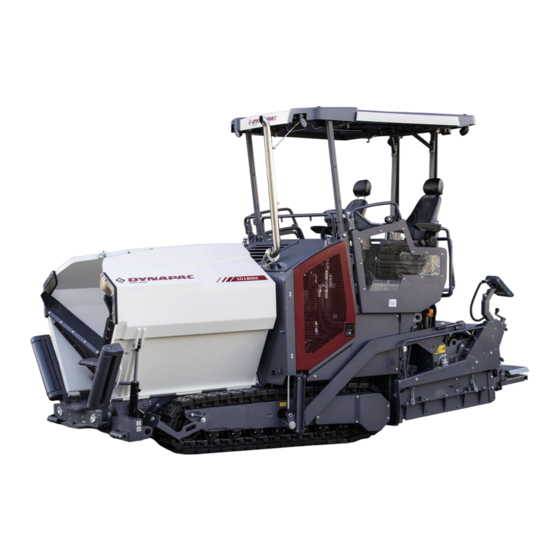
B Vehicle description Application The Dynapac SD1800C paver finisher is a paver finisher with a caterpillar drive which is used for paving bituminous mixed material, roll-down or lean-mixed concrete, track- laying ballast and unbound mineral aggregates for foundations for paving. -
Page 26: Description Of Assemblies And Functions
Description of assemblies and functions Item Designation Material compartment (hopper) Truck push rollers Sensor rod (direction indicator) Caterpillar drive Levelling cylinder for paving thickness Traction roller Crossbeam pull bar Paving thickness indicator Crossbeam Travel drive of the caterpillar drive Auger Screed Operator’s platform Operating panel (can be moved to either side) -
Page 27: Vehicle
Vehicle Construction The paver finisher has a welded steel frame on which the individual components are mounted. The caterpillar drives compensate uneven areas on the ground; the suspension of the attached screed additionally helps to attain high paving precision. The continuously adjustable hydrostatic travel drive allows the speed of the paver fin- isher to be matched to all work conditions. - Page 28 Engine: The paver finisher is driven by a water cooled diesel engine. For further de- tails see the technical data and the engine's instruction manual. Drive unit: Both caterpillar drives are directly driven by separate drives. They operate directly, without any drive chains which require maintenance or servicing. The tension of the caterpillar chains can be readjusted using tensioners.
- Page 29 Material compartment (hopper): The hopper inlet is equipped with a conveyor sys- tem that empties the hopper and transfers the material to the auger. The hopper can hold approx. 10.5 t. To facilitate emptying and achieve even material transfer, each of the lateral covers of the hopper can be hydraulically folded in.
- Page 30 Levelling/slope control system: The slope control system (o) allows the traction point to be regulated at the left-hand or the right-hand side with a defined difference to the opposite side. To determine the actual value, the two traction crossbeams are linked with a slope control rod.
-
Page 31: Danger Zones
Danger zones WARNING Danger for persons in the danger zone Persons in the danger zone can suffer severe or fatal inju- ries from movements and functions of the vehicle! - Remaining in the vehicle's danger zone during operation is prohibited! - During operation, only the vehicle operator and the screed personnel are allowed on the vehicle or in the danger zone. -
Page 32: Safety Devices
Safety devices 4 5 6 7... - Page 33 Item Designation Hopper transport safeguard Crossbeam lock, mechanical Main switch Emergency stop button Horn Ignition key Lights Protective roof latch (o) Fire extinguisher (o) Screed warning light (o) Covers, lateral flaps, coverings Rotary beacon (o) Located on both sides of the vehicle Safe operation is only possible when all operating and control elements are function- ing correctly and when all safety devices are in position.
-
Page 34: Technical Data, Standard Configuration
Technical data, standard configuration Dimensions (all dimensions in mm) 2125 2900 6145 6400 1990 2550 3290 3400 For screed technical data, refer to the screed operating instructions. B 10... -
Page 35: Allowed Angle Of Rise And Slope
Allowed angle of rise and slope max. 15° max. 15° max. 15° max. 15° Before operating your vehicle in an inclined position (gradient, slope, lateral inclination) which is above the specified limit value, please consult the custom- er service department for your vehicle! Permissible approach angle max. -
Page 36: Weights (All Weights In T)
Weights (all weights in t) Paver finisher without screed approx. 8.9 Paver finisher with screed: - V3500 approx. 10.5 With extension parts for max. approx. 0.52 working width, additionally max.: With filled hopper approx. 10.5 additionally max. For the weights of the screed and the screed attachments, see the operating instruc- tions for the screed. -
Page 37: Capacity Data
Capacity data V3500TV(E) 1,75 3,50 Transport speed 0 - 4 km/h Operating speed 0 - 25 m/min Paving height -120 - 200 Max. grain size Theoretical paving performance B 13... -
Page 38: Travel Drive/Traction Unit
Travel drive/traction unit Drive Hydrostatic drive, continuously controllable Two separately driven caterpillar drives Drive unit with rubber grouser chains Turning capacity Turning on the spot Speed See above Engine EU 3A / Tier 3 (o) Make/type Deutz TD 2.9 L4 Version 4-cylinder diesel engine Performance... -
Page 39: Material Compartment (Hopper)
5.10 Material compartment (hopper) Volume Approx. 4.8 m = approx. 10.5t Minimum inlet height, centre 520 mm Minimum inlet height, outside 605 mm Hopper width, outside, open 3400 mm 5.11 Material transfer Type Dual conveyor belt Width 2 x 350 mm Conveyors Left and right auger separately controllable Drive... -
Page 40: Screed Lifting Device
5.13 Screed lifting device At standstill: Special functions - Screed stop Mechanical grade control Levelling system Optional systems with and without slope control 5.14 Electrical system On-board voltage 24 V Batteries 2 x 12 V, 74Ah Alternator (o) 12.5 kVA / 400V 5.15 Permissible temperature ranges Operation... -
Page 41: Identification Points
Identification points CAUTION Danger due to missing or misunderstood vehicle signs Missing or misunderstood vehicle signs pose a danger of injuries! - Never remove any warnings or information signs from the vehicle. - Damaged or lost warning or information signs must be replaced immediately. - Page 42 B 18...
- Page 43 xxxxxxxxxxxxxxxxx B 19...
-
Page 44: Warning Signs
Warning signs Pictogram Meaning - Warning - Operating instructions! Danger due to improper operation. The vehicle personnel must have read and understood the safety, operating and maintenance instructions for the vehicle before the vehicle is put into operation! Failure to comply with the operating and warning instructions can cause severe or fatal injuries. - Page 45 Pictogram Meaning - Warning - danger of crushing fingers and hands due to moving, accessible vehicle parts! Crushing points can cause severe inju- ries with the loss of parts of the fingers or hand. Keep your hands at a safe distance from the danger area! - Warning - Spring-loaded part! Performing work incorrectly can cause...
- Page 46 Pictogram Meaning - Warning - danger from improper transportation! Always sit down with the seatbelt fas- tened to drive the vehicle forwards/in re- verse at transport speed! Driving the vehicle when standing up / without the seatbelt fastened can cause severe or fatal injuries.
-
Page 47: Information Signs
Information signs Pictogram Meaning - Operating Instructions Position of the storage compartment. - Lifting point Lifting the machine is only permitted at these lifting points! - Lashing point Lashing the machine is only permitted at these points! - Main battery switch Position of the main battery switch. - Page 48 Pictogram Meaning - Engine oil Position of the filling and control point. - Engine oil drainage point Position of the drainage point. - Engine coolant Position of the filling and control point. - Hydraulic oil Position of the filling point. - Hydraulic oil level Position of the control point.
-
Page 49: Ce Marking
Pictogram Meaning - Gear oil drainage point Position of the drainage point. CE marking No. Pictogram Meaning - CE, sound output level B 25... -
Page 50: Instructive Symbols, Prohibitive Symbols, Warning Symbols
Instructive symbols, prohibitive symbols, warning symbols No. Pictogram Meaning - Wear ear protectors - Do not spray the area or component with water! - Warning on dangers posed by batteries! - First aid kit B 26... -
Page 51: Danger Symbols
Danger symbols No. Pictogram Meaning - XN: Danger to health! This substance can damage your health when absorbed in the body! Substance irritating to skin, eyes and res- piratory system; can cause inflammation. Avoid contact with the human body; also avoid inhaling the vapours and seek medical advice if feeling unwell. -
Page 52: Further Warnings And Operating Instructions
Further warnings and operating instructions Pictogram Meaning - Warning - Hazard from unsupported screed! If the screed sags, this can cause severe or fatal injuries! Insert crossbeam lock only at crown adjustment "zero". Cross- beam lock only for transportation! Do not enter or work under screed only secured with screed lock for transportation! - Attention - danger of high voltage in... -
Page 53: Identification Label For The Paver Finisher (41)
Identification label for the paver finisher (41) Item Designation Paver finisher type Year of construction Operating weight, incl. all extension parts, in kg Maximum permitted total weight in kg Max. permissible load on the front axle, in kg Max. permissible load on the rear axle, in kg Maximum permissible axle load of the trailer axle in kg (o) Rated performance in kW Product identification number (PIN) -
Page 54: Explanation Of 17Pin Serial Number
Explanation of 17PIN serial number >10002014JHG002076< - Manufacturer - Family/Model - Check letter - Serial number B 30... -
Page 55: Engine Type Plate
Engine type plate The engine type plate (1) is affixed on top of the engine. The type plate states the engine type, serial number and engine data. Please state the engine number of the engine when ordering spare parts. See also operating instructions for the engine. B 31... -
Page 56: Standards
EN standards Continuous sound pressure level The operator always must use ear protection. The emission value at the ear of the driver varies depending on the materials used for paving and may even rise above 85 dB(A). If no ear protection devices are used, hearing can be impaired. The sound emission level of the paver finisher was measured under free-field condi- tions according to EN 500-6:2006 and ISO 4872. -
Page 57: Vibration Acting On The Entire Body
Vibration acting on the entire body When the vehicle is used properly, the weighted effective acceleration values at the driver’s seat of a = 0.5 m/s according to DIN EN 1032 are not exceeded. Vibrations acting on hands and arms When the vehicle is used properly, the weighted effective acceleration values at the driver’s seat of a = 2.5 m/s... - Page 58 B 34...
-
Page 59: C11.18 Transportation
C 11.18 Transportation Safety regulations for transportation Accidents can happen when the paver finisher and the screed are not properly pre- pared for transportation or when transportation is carried out improperly! Reduce both the paver finisher and the screed to their basic widths. Remove all pro- truding parts (such as the automatic levelling system, auger limit switches, aprons, etc.). -
Page 60: Directing Of The Vehicle
Directing of the vehicle WARNING Danger due to incorrect directing of the vehicle A banksman must be used when visibility is impaired on roads or transport roads and when loading the vehicle. Incorrectly implemented or misunderstood directions given by the banksman can cause severe to fatal injuries! The banksmen assigned for directing vehicles may only consist of personnel - who have been trained for directing machines and can... -
Page 61: Transportation On Low-Bed Trailers
Transportation on low-bed trailers Reduce the paver finisher and the screed to their basic widths; also remove any at- tached side plates. The maximum approach angle is indicated in the section entitled "Technical data"! Check the fill level of the operating substances so that these do not escape when driv- ing on an incline. - Page 62 Operation Buttons Deactivating the function lock Activate set-up mode. Close the hopper lids. Engage both hopper transport safeguards. Lift the screed. Insert the transportation safeguards of the screed. Fully extend the levelling cylinder. C 11.18 4...
- Page 63 Operation Buttons Retract the screed parts until the screed matches the basic width of the paver finisher. Deactivate set-up mode. C 11.18 5...
-
Page 64: Securing The Load
Securing the load The following instructions for securing the load on the low-bed trailer consist merely in examples of how to secure the load correctly. Always comply with the local regulations for securing the load and for correct use of load securing equipment. -
Page 65: Driving Onto The Low-Bed Trailer
Driving onto the low-bed trailer Make sure that there are no persons in the danger area during loading. NOTE Caution! Possible collision of parts - When driving up inclines, lock the lane clearer in the upper position. - Use the work gear and low engine speeds to drive onto the low-bed trailer. C 11.18 7... -
Page 66: Lashing Equipment
Lashing equipment Use the load securing equipment, lashing straps and chains belonging to the vehicle. Additional shackles, eyebolts, edge guards and non-slip mats may be needed de- pending on the type of load securing equipment. Always comply with the stated values for permitted lashing force and load rating! Always tighten the lashing chains and straps hand-tight (100-150 daN). -
Page 67: Loading
Loading Pay attention to load distribution during loading! On some vehicles, the kingpin load is too low so that the load has to be positioned further to the back of the vehicle. Always heed the details regarding load distribution stipulated for the vehicle together with the centre of gravity of the paver finisher. -
Page 68: Preparing The Vehicle
Preparing the vehicle After the vehicle has been positioned on the low-loader, the following preparations must be carried out: - Close hopper, set hopper transport safeguards (1). - Position the non-slip mats under the screed across the whole width of the vehicle (2) and lower the screed. -
Page 69: Securing The Load
Securing the load Securing at the front Fasten lashing chains at the front Diagonal lashing secures the paver finisher at the front using the lashing points on the paver finisher and on the low-load trailer. Fasten the lashing chains as shown. Shackles have to be used: To ensure that lashing chains can be fitted securely on the left and on the right, a shackle has to be fitted at each of the lashing points (1) provid- ed on the paver finisher for the lashing equipment... -
Page 70: Securing At The Rear
Securing at the rear Fasten lashing chains Diagonal lashing secures the paver finisher at the rear using the lashing points on the paver finisher and on the low-load trailer. Fasten the lashing chains as shown. Permissible angles see "Securing at the front". C 11.18 12... -
Page 71: After Transportation
After transportation - Remove the attachment devices. - Raise protective roof: See section entitled "Protective roof" - Start engine. - Lift the screed to the transportation position. - Drive from the trailer at a low engine revs/speed. - Park the paver finisher in a secure spot, lower the screed and switch off the engine. - Remove the key and/or cover the operating panel with the protective hood and se- cure it. -
Page 72: Protective Roof (O)
Protective roof (o) NOTE Caution! Possible collision of parts The following adjustments must be made before lowering the roof: - Both seat consoles pushed in. - Backrests and armrests of driver's seats tilted forwards. - Operating panel in lowest position and locked with the vandalism protection facility. - Page 73 Version 1: The exhaust pipe is lowered or raised together with the roof. - Connect the pump lever (1) to the pump (2). - Tighten bolts (3) on both sides of the roof. - Set the adjustment lever (4) to the "Raise" or "Lower" position. - Operate the pump lever (1) until the roof has reached the upper or lower limit position.
- Page 74 Version 2: - Connect the pump lever (1) to the pump (2). - Tighten bolts (3) on both sides of the roof. - Set the adjustment lever (4) to the "Raise" or "Lower" position. - Operate the pump lever (1) until the roof has reached the upper or lower limit position. - Bolt (3) must be inserted in the corresponding hole on both sides of the roof: - Position (3a): Roof raised.
-
Page 75: Transportation
Transportation Reduce the paver finisher and the screed to their basic widths; also remove any at- tached side plates. Preparations - Prepare the paver finisher for transportation (see chapter D). - Remove all overlaying or loose parts from finisher and screed (see also operating instructions for the screed). - Page 76 Operation Buttons Deactivating the function lock Activate set-up mode. Close the hopper lids. Engage both hopper transport safeguards. Lift the screed. Insert the transportation safeguards of the screed. Fully extend the levelling cylinder. C 11.18 18...
- Page 77 Operation Buttons Retract the screed parts until the screed matches the basic width of the paver finisher. Deactivate set-up mode. C 11.18 19...
-
Page 78: Driving Mode
Driving mode Operation Buttons Set the fast/slow switch to "Hare" if necessary. Turn the preselector to "zero". Swivel the drive lever to maximum. The vehicle already advances slightly on deflecting the drive lever! Adjust required vehicle speed with the preselector. To stop the vehicle, swivel the drive lever to the middle setting and set the preselec- tor to "zero". -
Page 79: Loading By Crane
Loading by crane WARNING Danger from suspended loads Crane and/or lifted vehicle can tip when lifted and cause injuries! - The vehicle may only be raised at the marked lifting points. - Heed the operating weight of the vehicle. - Do not enter the danger zone. - Use only lifting gear that can bear the load. - Page 80 Example: Four lifting eyes (1, 2) are provided for loading the vehicle with a crane. Depending on the type of screed which is used, the paver finisher's centre of gravity, with the screed mounted, is located in area (3) of the vehicle. - Secure vehicle wherever it is parked up.
- Page 81 See section entitled "Protective roof" - Attach lifting gear to the four attachment points (1, 2). The max. permissible attachment point load at the attachment points is: 73.0 kN. The permissible load applies in the vertical direction! Make sure that the paver finisher remains in a horizontal position during transportation! C 11.18 23...
-
Page 82: Towing
Towing Heed all regulations and apply all safety measures applicable for towing heavy construction machines. The towing vehicle must be capable of securing paver finisher, even on slopes. Use only approved tow bars! If necessary, remove any attachments and accessories from the paver finisher and the screed until the basic width has been attained. - Page 83 Two high-pressure cartridges (6) are lo- cated on both of the travel drive pumps (5). The following activities must be carried out to activate the towing function: - Loosen lock nut (7) half a turn. - Screw in the bolt (8) until increased re- sistance occurs.
-
Page 84: Safely Parking The Vehicle
Safely parking the vehicle When the paver finisher is parked at a lo- cation accessible to the public, it must be secured in such a way that unauthorised persons or playing children cannot dam- age the vehicle. - Pull off the ignition key and the main switch (1) and take it with you –... -
Page 85: Lifting The Vehicle With Hydraulic Lifts, Lifting Points
Lifting the vehicle with hydraulic lifts, lifting points The hydraulic lift must be rated for at least 10t. Always choose a horizontal surface with adequate load rating as installation surface for the hydraulic lift! Make sure that the hydraulic lift is securely and correctly positioned! The hydraulic lift is only intended to lift a load and not as a support. - Page 86 C 11.18 28...
-
Page 87: D11.18 Operation
D 11.18 Operation Safety regulations Starting the engine, the travel drive, the conveyor, the auger, the screed or the lifting devices can cause injuries or even the death of persons. Make sure before starting any of these devices that no-one is working at, in or be- neath the paver finisher or within its danger area! - Do not start the engine or do not actuate any controls when this is expressly forbidden! Unless otherwise specified, the controls may only be actuated when the engine... - Page 88 DANGER Danger due to improper operation Improper operation of the vehicles can cause severe to fatal injuries! - The vehicle may only be used in the proper manner for its intended purpose. - The vehicle may only be operated by trained staff. - The vehicle operators must have made themselves famil- iar with the contents of the operating instructions.
-
Page 89: Controls
Controls Operating panel All detent switch functions which may pose a risk on starting the diesel engine (auger and conveyor conveying function) are set to the STOP function in the case of EMERGENCY STOP or restarting the control system. If settings are changed when the diesel engine is stopped ("AUTO"... - Page 90 D 11.18 4...
- Page 91 Item Designation Brief description Press in an emergency (danger to persons, impending colli- sion, etc.)! Pressing the emergency stop button switches off the en- gine, the drives and the steering system. Making way, lifting the screed or other actions are then no Emergency stop longer possible! Danger of accidents! button...
- Page 92 D 11.18 6...
- Page 93 Item Designation Brief description For switching on the paver finisher functions and for continu- ously regulating the road speed – forward or reverse. Centre position: Engine in neutral; no travel drive; - To swivel the drive lever out, release by pulling the handle up.
- Page 94 D 11.18 8...
- Page 95 Item Designation Brief description For setting the maximum speed that can be reached when the drive lever is at its stop. The scale roughly matches the speed in m/min (during paving). Travel drive The vehicle must not travel at max. transport speed preselector when the hopper is full! The vehicle speed cannot be reduced to "0"...
- Page 96 D 11.18 10...
- Page 97 Item Designation Brief description Button with detent switch function and LED feedback: Front working - For switching on the front working lights lights - Switch OFF by pressing the button again ON / OFF (o) Avoid dazzling other road users! Button with detent switch function and LED feedback: - For switching on the rear working lights Rear working lights...
- Page 98 D 11.18 12...
- Page 99 Item Designation Brief description Detent switch function and LED feedback: Windscreen wip- - For switching on the windscreen wipers ers ON / OFF (o) - Switch OFF by pressing the button again Detent switch function and LED feedback: Windscreen wash- - For engaging the windscreen washer system + er system + wind- windscreen wipers...
- Page 100 D 11.18 14...
- Page 101 Item Designation Brief description Not used Button with detent switch function and LED feedback: Seat heating - For switching on the seat heating ON / OFF (o) - Switch OFF by pressing the button again Detent switch function and LED feedback: Extraction - To actuate the asphalt fume control system ON / OFF (o)
- Page 102 D 11.18 16...
- Page 103 Item Designation Brief description Not used D 11.18 17...
- Page 104 D 11.18 18...
- Page 105 Item Designation Brief description Button with detent switch function and LED feedback: - The vehicle turns on the spot (the caterpillar chains run in opposite directions) when the steering is set to "10". - Steering turned to the left = vehicle turns to the left - Steering turned to the right = vehicle turns to the right The function can only be activated in the working gear ("travel drive slow") speed.
- Page 106 D 11.18 20...
- Page 107 Item Designation Brief description Pushbutton function: - To close the left half of the hopper Separate actuation (o): Is required when paving in spaces where there is only Close hopper left limited space at one side or when obstacles obstruct truck unloading.
- Page 108 D 11.18 22...
- Page 109 The Truck Assist system is used for communication between the driver of the paver and the driver of the material truck. The corresponding signal system shows the truck driver which action to perform (reversing / stop / tip material / depart). Caution! Possible material damage through NOTE insufficient instruction...
- Page 110 D 11.18 24...
- Page 111 Item Designation Brief description LED display Pushbutton function with LED feedback: - To change over to the "Start Tipping" signal. (YELLOW SIGNAL, running light as- cending) - Press button again to change signal over to "Pause". Tell truck "Start (YELLOW SIGNAL, flashing). Tipping"...
- Page 112 D 11.18 26...
- Page 113 Item Designation Brief description LED display Pushbutton function with LED feedback: - The "Truck Assist" function runs automatically. - Switch OFF by pressing the button again - Press button (38) to request a truck with material / Release for truck to approach (GREEN SIGNAL) The truck is detected by a laser sensor at...
- Page 114 D 11.18 28...
- Page 115 Item Designation Brief description Pushbutton function: - To extend the left half of the screed This function is not used in vehicle configurations with Extend a screed which cannot be extended. left screed On actuation, heed danger zones of moving parts of the vehicle! Pushbutton function: - To extend the right half of the screed...
- Page 116 D 11.18 30...
- Page 117 Item Designation Brief description Button with detent switch function and LED feedback: - The conveying function of the left conveyor is switched on when the drive lever is swivelled out and is continuously controlled via the material limit switch- es in the material tunnel. - Switch OFF by pressing the button again Left conveyor The function is shut off by pressing the EMERGENCY...
- Page 118 D 11.18 32...
- Page 119 Item Designation Brief description Button with detent switch function and LED feedback: - The function of the left conveyor is permanently switched on at full conveying rate and is activated/de- activated with the material limit switch in the material tunnel. - Switch OFF by pressing the button again.
- Page 120 D 11.18 34...
- Page 121 Item Designation Brief description Pushbutton function: - The conveying direction of the conveyor can be re- versed in order to slightly reverse paving material for example which may be present in the material tunnel. The function can be triggered in all modes of the conveyor.
- Page 122 D 11.18 36...
- Page 123 Item Designation Brief description Button with detent switch function and LED feedback: - The conveying function of the left half of the auger is switched on when the drive lever is swivelled out and is continuously controlled via the material limit switches. - Switch OFF by pressing the button again Left auger The function is shut off by pressing the EMERGENCY...
- Page 124 D 11.18 38...
- Page 125 Item Designation Brief description Button with detent switch function and LED feedback: - The conveying function of the left half of the auger is switched on continuously with full delivery capacity, without material control via the limit switches. - Switch OFF by pressing the button again Left auger The function is shut off by pressing the EMERGENCY "MANUAL"...
- Page 126 D 11.18 40...
- Page 127 Item Designation Brief description Pushbutton function: - To manually trigger the conveying function for the left half of the auger, conveying direction inwards. Left auger The function can be triggered in all modes. "MANUAL" Conveying On manual triggering, the automatic function is overrid- direction inwards den with reduced delivery capacity.
- Page 128 D 11.18 42...
- Page 129 Item Designation Brief description Detent switch function and LED feedback: - In transport gear: To lock all functions relevant to paving. Despite "Auto" settings in the individual functions, these are not activated when the drive lever is swivelled out. LED permanently ON - In working gear: To lock all detent functions relevant to paving.
- Page 130 D 11.18 44...
- Page 131 Item Designation Brief description Pushbutton function: - For manual actuation of the levelling cylinders in the Adjustment button: corresponding direction (when the automatic levelling Retract / raise left system is switched off). levelling cylinder On actuation, heed danger zones of moving parts of the vehicle! Pushbutton function: - For manual actuation of the levelling cylinders in the...
- Page 132 D 11.18 46...
- Page 133 Item Designation Brief description Pushbutton function: - To adjust the auger height in the corresponding Adjustment button: direction. Raise auger (o) On actuation, heed danger zones of moving parts of the vehicle! Pushbutton function: - To adjust the auger height in the corresponding Adjustment button: direction.
- Page 134 D 11.18 48...
- Page 135 Item Designation Brief description Detent switch function and LED feedback: Filling function for the paving process. The diesel engine's speed is increased to the preselected nominal speed and all conveying functions set to "Auto- matic" (conveyor and auger) are engaged. The main function switch must be set to the OFF position.
- Page 136 D 11.18 50...
- Page 137 Item Designation Brief description Pushbutton function with LED feedback: - For lifting the screed (LED ON) and for switching off the "Screed floating position" function Check whether the screed transport safeguard Lift screed is inserted! On actuation, heed danger zones of moving parts of the vehicle! Button with detent switch function and LED feedback The main function switch must be set to the...
- Page 138 D 11.18 52...
- Page 139 Item Designation Brief description Button with detent switch function and LED feedback: - Tamper ON and OFF function. - Activation is carried out by swivelling the drive lever out. - Switch OFF by pressing the button again. Tamper (screed-specific) The main function switch must be set to the OFF position.
- Page 140 D 11.18 54...
- Page 141 Item Designation Brief description Not used Not used D 11.18 55...
- Page 142 D 11.18 56...
- Page 143 Item Designation Brief description Not used Not used D 11.18 57...
- Page 144 D 11.18 58...
- Page 145 The "Set Assist" function prepares the paver to relocate to another section of road- works or for transportation. When the function is activated, previously selected vehicle functions are carried out to make the vehicle ready for transport. The function can be reset after relocating the paver. This restores the corresponding elements to the previously saved working condition /position.
-
Page 146: Remote Control
Remote control D 11.18 60... - Page 147 Depending on the side of the vehicle, the button blocks (A) and (B) are assigned to either the auger or the conveyor control system. The relevant element which is con- trolled is indicated by an illuminated symbol (C). Important! Do not disconnect remote controls during operation! This causes the paver finisher to be shut down! D 11.18 61...
- Page 148 D 11.18 62...
- Page 149 Item Designation Brief description Press in an emergency (danger to persons, impending colli- sion, etc.)! Pressing the emergency stop button switches off the en- gine, the drives and the steering system. Making way, lifting the screed or other actions are then no Emergency stop longer possible! Danger of accidents! button...
- Page 150 D 11.18 64...
- Page 151 Item Designation Brief description Button with detent switch function and LED feedback: - The conveying function of the corresponding half of the auger is switched on continuously with full deliv- ery capacity, without material control via the limit switches. Auger - Switch OFF by pressing the button again "MANUAL"...
- Page 152 D 11.18 66...
- Page 153 Item Designation Brief description Pushbutton function: - Plus/minus buttons for adjusting the delivery capacity. - The delivery capacity is slowed down or speeded up Auger delivery depending on the length of time for which the button capacity is pressed. The auger function must be switched to "AUTO" or "MANUAL"...
- Page 154 D 11.18 68...
- Page 155 Item Designation Brief description Button with detent switch function and LED feedback: - The conveying function of the corresponding half of the conveyor is switched on continuously with full de- livery capacity, without material control via the limit switches. Conveyor - Switch OFF by pressing the button again "MANUAL"...
- Page 156 D 11.18 70...
- Page 157 Item Designation Brief description Pushbutton function: - Plus/minus buttons for adjusting the delivery capacity. - The delivery capacity is slowed down or speeded up Conveyor delivery depending on the length of time for which the button capacity is pressed. The conveyor function must be switched to "AUTO" or "MANUAL"...
- Page 158 D 11.18 72...
- Page 159 Item Designation Brief description Button with detent switch function and LED feedback: Operating mode - Operating mode "AUTO" (LED ON): Levelling levelling engages automatically when the drive lever "AUTO" / is swivelled out for paving operation. "MANUAL" - Operating mode "MANUAL" (LED OFF): left levelling switched off.
- Page 160 D 11.18 74...
- Page 161 Item Designation Brief description Button with detent switch function and LED feedback: Operating mode - Operating mode "AUTO" (LED ON): Levelling levelling engages automatically when the drive lever "AUTO" / is swivelled out for paving operation. "MANUAL" - Operating mode "MANUAL" (LED OFF): right levelling switched off.
- Page 162 D 11.18 76...
- Page 163 Item Designation Brief description Pushbutton function: - For manual actuation of the levelling cylinders on the corresponding side of the vehicle when the automatic Levelling cylinder levelling system is switched off (LED OFF). manual On adjustment, note the levelling display in the remote control display! Pushbutton function: - To retract and extend the screed half on the corre-...
- Page 164 D 11.18 78...
-
Page 165: D23.18 Operating The Display
D 23.18 Operating the display D 23.18 1... -
Page 166: Operation Of The Input And Display Terminal
Operation of the input and display terminal Button layout on the display - (A) Jog dial (knob to be turned+push button): - Turn: - to select various adjustment parameters within a menu - to adjust the parameter - to select various selection possibilities within a menu - Press: - to release the adjustment of a parameter - to confirm a parameter adjustment... - Page 167 To confirm an active/opened menu, the colour of the cor- responding symbol changes from pale to dark grey! - (F) Display area for status, warning and error messages: - To show current earnings or error messages. The colour of the symbol indicates whether it is a status, warning or error message. Colour code Explanation RED - error message...
-
Page 168: Menu Operation - Procedure For Adjusting Parameters
Menu operation - procedure for adjusting parameters D 23.18 4... - Page 169 Example: Adjusting the screed temperature - The "Home" menu is open in the display. - Press button (A) to open the "Engine Speed" menu. - The "Engine Speed" menu is open in the display. - Press button (B) to open the "Screed Heater" menu. - Turn jog dial (C) to make the cursor appear.
-
Page 170: Selecting And Changing An Adjustment Parameter In A Menu
Selecting and changing an adjustment parameter in a menu - Press jog dial (C) to activate the parameter adjustment. A blue frame appears around the top adjustment parameter in the menu. - Turn jog dial (C) in the corresponding direction until the blue frame is around the required adjustment parameter. -
Page 171: Selecting And Changing A Selection Possibility In A Menu
Selecting and changing a selection possibility in a menu - Press jog dial to activate the parameter adjustment. A blue frame appears around the top selection possibility in the menu. - Turn jog dial in the corresponding direction until the blue frame is around the re- quired selection possibility. -
Page 172: Menu Structure
Menu structure Menu of the "Home" displays Displays: - (1) Speed: - Paving (tortoise)-(m/min) / (ft/min) - Driving (hare) - (km/h) / (mph) - (2) Fuel gauge - (4) Paving material - conveyor level left / right - (5) Paving material - auger level left / right - (6) Actual temperature of the screen heater (°C) / (°F) The display shows the average temperature of all screed sections. -
Page 173: Home" Menu - Sub-Menus
"HOME" menu - sub-menus Open the following sub-menus: - (1) Show "Home" functions / "Quick Settings" - (2) Call "Engine Speed" menu / Engine measured value display + sub-menus. - (3) "Paving Parameters" menu + sub-menus. - (5) "Error Memory" menu + sub-menus. - (6) "Basic"... - Page 174 If the corresponding function button of an opened sub-menu is pressed again, the Home menu appears and the sub-menu display remains. D 23.18 10...
-
Page 175: Home" Functions / "Quick Settings
"Home" functions / "Quick Settings" Menu for directly activating various functions. - Press corresponding function button to show the functions / quick settings (1) to (6). Press once more to hide the functions again. Pressing the adjacent function button activates or deac- tivates the functions. - Page 176 As confirmation, the display changes for 5 to 10 seconds during saving. The functions and elements for the "Set Assist" function are selected in the corresponding menu. The "Set Assist" function prepares the paver to relocate to another section of road- works or for transportation.
-
Page 177: Engine Speed" Menu / Engine Measured Value Display
"Engine Speed" menu / Engine measured value display Menu for adjusting the engine speed and for checking various measured values of the engine. - (1) Nominal speed display and adjustment parameters Adjusted directly by pressing the job dial. Adjustment is carried out in steps of 50; the engine speed is adapted directly. - (2) Actual engine speed - (3) Engine oil pressure (bar) - (4) On-board voltage (V) -
Page 178: Material Management" Measured Value Display
"Material Management" measured value display Menu for checking the following parameters: - (1) Paving material level (%) conveyor left - (2) Paving material level (%) conveyor right - (3) Paving material level (%) auger left - (4) Paving material level (%) auger right - (5) Tamper speed (n/min) - (6) Vibrations speed (n/min) D 23.18 14... -
Page 179: Screed Heater" Adjustment And Display Menu (O)
"Screed Heater" adjustment and display menu (o) Menu for adjusting the nominal screed heater temperature and for checking the actu- al temperatures. - (1) Nominal screed heater temperature display and adjustment parameters. Press encoder (A) to start the editing menu. Setting range 50-180°C - (2) Average actual temperature of all screed sections (°C) / (°F) - (3) Actual temperature basic screed left (°C) / (°F) -
Page 180: Paving Area / Automatic Steering Unit" Menu
"Paving Area / Automatic Steering Unit" menu Menu for querying and resetting the current paving distance. - (1) Current paving distance (m) - Reset / set value to zero: Select function (1.1) with the job dial and press to reset. As confirmation, the display changes for 5 to 10 seconds during reset. -
Page 181: Paving Parameters" Menu
"Paving parameters" menu Menu for showing and adjusting the paving parameters. - (1) Current course thickness parameter - The following course thickness parameters can be selected: - (1a) Surface course >, low paving speed - (1b) Surface course >>, high paving speed - (1c) Binder course >, low paving speed - (1d) Binder course >>, high paving speed - (1e) Foundation... - Page 182 - (2) Left conveyor speed (%) display and adjustment parameters - (3) Right conveyor speed (%) display and adjustment parameters - (4) Left auger speed (%) display and adjustment parameters - (5) Right auger speed (%) display and adjustment parameters - (6) Nominal tamper speed (n/min) display and adjustment parameters - (7) Nominal vibration speed (n/min) display and adjustment parameters Tamper and vibration range depending on screed type.
-
Page 183: Adjusting The Paving Parameters
Adjusting the paving parameters Functions: - (8) "Save Parameter" function As confirmation, the display changes for 5 to 10 seconds during saving. - (9): "Load Parameter" function As confirmation, the display changes for 5 to 10 seconds during loading. - (10): "Parameter Reset - Load Factory Settings" function Firstly the system requests reset confirmation. - Page 184 Overview "Course Thickness Parameters" Menu for viewing the speeds saved for all conveying and compacting elements ac- cording to the course thickness parameters. Back to the main menu: - (1) "Paving Parameters" menu. D 23.18 20...
-
Page 185: Error Memory" Menu
"Error Memory" menu Menu for retrieving existing error messages. - (1) Number of error messages with travel drive stop. - Open detailed display "Error Messages With Travel Drive Stop": (1.1). - (2) Number of vehicle warning messages. - Open detailed display "Vehicle Warning Messages": (2.1). - (3) Number of engine error messages. -
Page 186: Detailed Display "Error Messages With Travel Drive Stop
Detailed display "Error Messages With Travel Drive Stop" Display of existing error messages in a table. - (1) Error code. - (2) Error description. - (3) Designation of the faulty part as per BMK/EIC list. Press the job dial to scroll through the list. D 23.18 22... -
Page 187: Detailed Display "Vehicle Warning Messages
Detailed display "Vehicle Warning Messages" Display of existing error messages in a table. - (1) Error code. - (2) Error description. - (3) Designation of the faulty part as per BMK/EIC list. Press the job dial to scroll through the list. - Delete list of error messages: (4). -
Page 188: Detailed Display "Engine Error Messages
Detailed display "Engine Error Messages" Display of existing error messages in a table. - (1) SPN code. - (2) FMI code. - (3) OC error frequency. All error messages can be identified in the section "Error codes drive engine". Press the job dial to scroll through the list. D 23.18 24... -
Page 189: Basic" Menu
"Basic" menu The "Basic" menu can be opened from every menu, sub-menu or display. Menu for opening the following sub-menus: - (1) "Home" menu - Display and quick settings menu. - (2) "Service" menu - Menu for service technician (password required) - (3) "Info &... - Page 190 "Service" menu Password-protected menu for various service settings. D 23.18 26...
-
Page 191: Info & Settings" Menu
"Info & Settings" menu Menu for calling up various vehicle information and sub-menus for various settings. Display of the following information: - (1) Software version of the vehicle - (2) Software version of the display - (3) Engine operating hours (h) - (4) Next service interval (h) If consultation with Technical Support is required for your vehicle, always specify the software version! -
Page 192: Screed" Set-Up Menu
"Screed" set-up menu Menu for setting up the basic screed settings and screed functions. - (1) Display and adjustment parame- ters for the screed type - Screed type 1, 2, 3, 4, 5 Please consult the screed type plate for the parameter to be entered here, corre- sponding to the last number of the screed type. - Page 193 - (4) Display and adjustment parameters for the central lubrication system - (4.1): Extended lubrication interval - (4.2): Standard lubrication interval - (4.3): Shortened lubrication interval If necessary, the lubrication interval has to be adjusted to the prevailing paving situ- ation and to the material.
-
Page 194: Paving / Travel" Set-Up Menu
"Paving / Travel" set-up menu Menu for setting up the vehicle and levelling functions. - (1) Display and adjustment parameters for "Delayed Front Hopper" - delay time (sec). (o) After closing the hopper lids, the front hopper is only raised after the adjusted time has expired. - Page 195 - (3) Selection "Cross Levelling" - (0): Cross levelling OFF - (1): Only data display of the opposite side of the vehicle. - (2): Data display and control of the opposite side of the vehicle. - (3): Split screen on the remote controls: simultaneous data display and operation of both sides of the vehicle possible.
-
Page 196: Truck Assist / Set Assist" Set-Up Menu
"Truck Assist / Set Assist" set-up menu Menu for setting up the "Truck Assist" and "Set Assist" functions. - (1) Selection "Truck Distance" In order to adjust to the prevailing situation, the truck’s automatic detection function can be preset to 3 different distances (paver/truck). - (1.1): Shortened distance - (1.2): Medium distance - (1.3): Extended distance... -
Page 197: Day/Night Lighting" Set-Up Menu
"Day/Night Lighting" set-up menu Menu for adjusting the illuminance of various control elements. - (2) Monitor brightness display and adjustment parameters - (2.1): and adjustment parameters (daytime light) - (2.2): and adjustment parameters (nighttime light) - (3) Truck Assist display and adjustment parameters - (3.1): and adjustment parameters (daytime light) - (3.2): and adjustment parameters (nighttime light) Setting range 0-100%... -
Page 198: Display" Set-Up Menu
"Display" set-up menu Menu for setting up basic display settings. - (1) Selection "System Language" - English / German - (2) Selection "Units of measurement" - Metric / Imperial (US) - (3) "Time" display and adjustment parameters - h/h : min/min - 24h / PM/AM - (4) "Date"... - Page 199 "Licence text" display Display of the software licence text. Back to the main menu: - (1) "Display" set-up menu. D 23.18 35...
-
Page 200: Terminal Error Messages
Terminal error messages Status, warning and error messages symbols Command Symbol in the display High beam headlights control The high beam headlights are switched on. Avoid dazzling the oncoming traffic! Check direction of travel indicator Flashes whenever direction of travel indicator is activated. - Page 201 Command Symbol in the display ® Indicator lamp AdBlue / DEF ® The level of AdBlue / DEF is insufficient. Level 10% - display flashes Level 5% - display stays on permanently Level 0% - drive engine is throttled to emergency mode Indicator lamp platform lock.
- Page 202 Command Symbol in the display Error message Indicates that there is a drive engine fault. Depend- ing on the type of fault, the vehicle can temporarily continue to be operated or, in the case of serious faults, should be shut down immediately to prevent further damage from occurring.
- Page 203 Command Symbol in the display Pending service: A maintenance interval is about to expire. Proceed immediately with maintenance to avoid subsequent damage! Service overdue: A maintenance interval is overdue. Proceed immediately with maintenance to avoid subsequent damage! D 23.18 39...
- Page 204 Command Symbol in the display - Error message "Engine Malfunction" There is a malfunction in the engine. Switch off the drive engine immediately! Error details can be viewed in the "Error Memory" display menu. Lights up for a few seconds once the igni- tion has been switched on for checking pur- poses.
- Page 205 Command Symbol in the display Engine stop: Display for all error messages with machine stop. Hydraulic filter. The hydraulic filter must be replaced. Replace filter element acc. to Maintenance Instructions! Engine oil pressure The oil pressure is insufficient. Switch off the engine immediately! For further possible faults, see Engine's op- erating instructions.
-
Page 206: Drive Engine Error Codes
Drive engine error codes If a fault is detected on the engine, this is shown by the corresponding indication (1) in the display. D 23.18 42... - Page 207 The error message that can be viewed in the corresponding menu contains several numerical codes, which clearly define the fault after decoding. Press the job dial to scroll through the list. It may be possible to continue operating the vehicle, depending on the severity of the error.
- Page 208 Example: D 23.18 44...
- Page 209 Explanation: Warning light and display signal a serious fault on the drive engine with automatic or necessary engine shut-down. Display: SPN: FMI: Cause: Cable break on sensor for rail pressure. Effect: Engine shut-down. Frequency: Fault occurs for the 1st time. Notify customer service of the error number displayed on your paver finisher;...
-
Page 210: Error Codes
Error codes Code Error Identification Short Text Detail 2-2-6 Air flow sensor; sensor error Air flow sensor load correction factor exceeding the maximum drift limit; plausibility error 2-2-6 Air flow sensor; sensor error Air flow sensor load correction factor exceeding drift limit;... - Page 211 Code Error Identification Short Text Detail 523911 7-2-3 Burner dosing valve (DV2); short circuit Burner dosing valve (DV2); short circuit to bat- to battery tery 523911 7-2-3 Burner dosing valve (DV2); short circuit Burner dosing valve (DV2); short circuit to bat- to battery tery on high side 523911...
- Page 212 Code Error Identification Short Text Detail 2-2-5 Sensor error coolant temperature; signal Sensor error coolant temperature; signal range range check low check low 2-3-2 Coolant temperature; system reaction High coolant temperature; warning threshold initiated exceeded 2-3-2 Coolant temperature; system reaction High coolant temperature;...
- Page 213 Code Error Identification Short Text Detail 523717 5-9-5 Timeout Error of CAN-Transmit-Frame Timeout Error of CAN-Transmit-Frame Amb- AmbCon; Weather environments Con; Weather environments 523603 3-3-8 Timeout Error of CAN-Receive-Frame Timeout Error of CAN-Receive-Frame AMB; AMB; Ambient Temperature Sensor Ambient Temperature Sensor 3224 5-9-6 NOx Sensor;...
- Page 214 Code Error Identification Short Text Detail 523942 7-6-7 Timeout Error (BAM to BAM) for CAN- Timeout Error (BAM to BAM) for CAN-Receive- Receive-Frame AT1OGCVol2 informa- Frame AT1OGCVol2 information; factors & tion; factors & Sensorcalibration for NOX Sensorcalibration for NOX Sensor (SCR-sys- Sensor (SCR-system downstream cat;...
- Page 215 Code Error Identification Short Text Detail 523788 6-5-5 Timeout Error of CAN-Transmit-Frame Timeout Error of CAN-Transmit-Frame TrbCH; TrbCH; Status Wastegate Status Wastegate 523605 1-1-8 Timeout Error of CAN-Receive-Frame Timeout Error of CAN-Receive-Frame TSC1AE; Traction Control TSC1AE; Traction Control 523606 1-1-9 Timeout Error of CAN-Receive-Frame Timeout Error of CAN-Receive-Frame TSC1AR;...
- Page 216 Code Error Identification Short Text Detail 3-1-2 Sensor error environment temperature; Sensor error environment temperature; signal signal range check high range check high 3-1-2 Sensor error environment temperature; Sensor error environment temperature; signal signal range check low range check low 2-1-2 Speed detection;...
- Page 217 Code Error Identification Short Text Detail 2-2-8 Sensor error water in fuel; signal range Sensor error water in fuel; signal range check check low 2-1-6 Sensor error low fuel pressure; signal Sensor error low fuel pressure; signal range range check high check high 2-1-6 Sensor error low fuel pressure;...
- Page 218 Code Error Identification Short Text Detail 523917 7-1-8 Physical range check high for DV1 & Physical range check high for DV1 & DV2 DV2 upstream pressure; shut off regen- upstream pressure; shut off regeneration eration 523917 7-1-8 Physical range check low for DV1 & DV2 Physical range check low for DV1 &...
- Page 219 Code Error Identification Short Text Detail 523350 1-5-1 Injector cylinder-bank 1; short circuit Injector cylinder-bank 1; short circuit 523352 1-5-2 Injector cylinder-bank 2; short circuit Injector cylinder-bank 2; short circuit 523354 1-5-3 Injector powerstage output defect Injector powerstage output defect 1-5-4 Injector 1 (in firing order);...
- Page 220 Code Error Identification Short Text Detail 523615 1-3-5 Metering unit (Fuel-System); short cir- Metering Unit (Fuel-System); short circuit to cuit to ground ground low side 1323 2-4-1 Too many recognized misfires in cylinder Too many recognized misfires in cylinder 1 (in 1 (in firing order) firing order) 1324...
- Page 221 Code Error Identification Short Text Detail 523612 5-5-5 ECU reported internal software error Internal ECU monitoring detection reported error 523612 5-5-5 ECU reported internal software error Internal ECU monitoring detection reported error 523008 4-2-4 Manipulation control was triggered Manipulation control was triggered 523008 4-2-4 Timeout error in Manipulation control...
- Page 222 Code Error Identification Short Text Detail 523919 6-9-4 Physical range check high for airpump Physical range check high for airpump pres- pressure; shut off regeneration sure; shut off regeneration 523919 6-9-4 Physical range check low for airpump Physical range check low for airpump pressure; pressure;...
- Page 223 Code Error Identification Short Text Detail 3253 6-9-2 Sensor error differential pressure (DPF); Sensor error differential pressure (DPF); signal signal range check high range check high 3253 6-9-2 Sensor error differential pressure (DPF); Sensor error differential pressure (DPF); signal signal range check low range check low 523009 2-5-3...
- Page 224 Code Error Identification Short Text Detail 523452 1-4-3 Multiple Stage Switch engine torque limi- Multiple Stage Switch engine torque limitation tation curve; plausibility error curve; plausibility error 1176 6-8-0 Sensor error pressure sensor upstream Sensor error pressure sensor upstream tur- turbine;...
- Page 225 Code Error Identification Short Text Detail 523723 8-7-4 Detection of AdBlue filled SCR system in Detection of AdBlue filled SCR system in Init- Init-State State 523632 8-7-5 Pump pressure SCR metering unit too Pump pressure SCR metering unit too high high 523632 8-7-6...
- Page 226 Code Error Identification Short Text Detail 2-2-6 Handthrottle; signal out of range, short Sesnor error handthrottle; signal range check circuit to battery high 1-2-6 Handthrottle; signal out of range, short Handthrottle idle validation switch; short circuit circuit to ground to ground 2-2-6 Sensor error accelerator pedal;...
- Page 227 Code Error Identification Short Text Detail 2-2-6 Plausibility error between APP1 and Plausibility error between APP1 and APP2 or APP2 or APP1 and idle switch APP1 and idle switch 523550 5-1-5 T50 start switch active for too long T50 start switch active for too long 2-2-6 Sensor error intake air;...
- Page 228 Code Error Identification Short Text Detail 1019 5-9-4 Actuator error EGR-Valve (2.9;3.6) or EGR-Valve (2.9;3.6) or Throttle-Valve (6.1,7.8); Throttle-Valve (6.1,7.8); internal error short circuit to battery 1020 5-9-4 Actuator error EGR-Valve (2.9;3.6) or EGR-Valve (2.9;3.6) or Throttle-Valve (6.1,7.8); Throttle-Valve (6.1,7.8); internal error short circuit to ground 1021 5-9-4...
- Page 229 Code Error Identification Short Text Detail 1068 1180 5-5-6 Sensor error exhaust gas temperature Sensor error exhaust gas temperature upstream turbine; signal range check low upstream turbine; signal range check low 1069 4361 6-6-8 Physical range check high for urea cata- Physical range check high for urea catalyst lyst upstream temperature upstream temperature...
- Page 230 Code Error Identification Short Text Detail 1094 4343 6-7-3 SCR heater relay urea pressureline; SCR heater relay urea pressureline primary open load side; open load 1096 4343 6-7-3 SCR heater urea pressureline; short cir- SCR heater urea pressureline; short circuit to cuit to battery battery 1097...
- Page 231 Code Error Identification Short Text Detail 1125 523632 6-6-5 Urea pump pressure; out of range Urea pump pressure sensor; low signal not plausible 1127 523632 6-6-5 Sensor error urea pump pressure; signal Sensor error urea pump pressure; signal range range check high check high 1128 523632...
- Page 232 Code Error Identification Short Text Detail 1169 523951 7-7-2 Zerofuel calibration injector 6 (in firing Zerofuel calibration injector 6 (in firing order); order); minimum value exceeded minimum value exceeded 1170 523612 5-5-5 ECU reported internal software error Internal software error ECU 1171 1-4-4 Oil temperature;...
- Page 233 Code Error Identification Short Text Detail 1223 5-9-4 Actuator error EGR-Valve (2.9;3.6) or Actuator EGR-Valve (2.9;3.6) or Throttle-Valve Throttle-Valve (6.1,7.8); internal error (6.1,7.8); open load 1224 5-9-4 Actuator error EGR-Valve (2.9;3.6) or Actuator EGR-Valve (2.9;3.6) or Throttle-Valve Throttle-Valve (6.1,7.8); internal error (6.1,7.8);...
- Page 234 Code Error Identification Short Text Detail 1257 523915 8-5-3 HCI dosing valve (DV1); blocked HCI dosing valve (DV1); blocked open 1258 524016 8-5-9 HFM sensor; electrical fault HFM sensor; electrical fault 1259 524016 8-5-9 Air Pump; air flow is not plausible Amount of air is not plausible to pump speed 1260 524016...
- Page 235 Code Error Identification Short Text Detail 1290 524043 Timeout error of CAN-Receive-Frame Timeout error of CAN-Receive-Frame ComMS_Sys6TO (error memory Slave); ComMS_Sys6TO (error memory Slave); Mas- Master-Slave internal CAN message ter-Slave internal CAN message 1291 524045 Master-Slave CAN; Message-Counter- Master-Slave CAN; Message-Counter-Error of Error of CAN-Receive-Frame Com- CAN-Receive-Frame ComMSMoFOvR MSMoFOvR...
- Page 236 Code Error Identification Short Text Detail 1337 2797 Injector diagnostics; timeout error of Injector diagnostics; timeout error of short cir- short circuit to ground measurement cyl. cuit to ground measurement cyl. Bank 0 Bank 0 1338 2798 Injector diagnostics; timeout error of Injector diagnostics;...
- Page 237 Code Error Identification Short Text Detail 1400 1136 6-8-1 Sensor error ECU temperature; signal Sensor error ECU temperature; signal range range check high check high 1401 1136 6-8-1 Sensor error ECU temperature; signal Sensor error ECU temperature; signal range range check low check low 1402 4769...
- Page 238 Code Error Identification Short Text Detail 1420 524012 7-7-2 Zerofuel calibration injector 8 (in firing Zerofuel calibration injector 8 (in firing order); order); maximum value exceeded maximum value exceeded 1421 524011 7-7-2 Zerofuel calibration injector 7 (in firing Zerofuel calibration injector 7 (in firing order); order);...
- Page 239 Code Error Identification Short Text Detail 1458 523960 7-7-1 Exhaust gas temperature EGR down- High exhaust gas temperature EGR cooler stream; out of range, system reaction ini- downstream; warning threshold exceeded tiated 1459 523960 7-7-1 Exhaust gas temperature EGR down- High exhaust gas temperature EGR cooler stream;...
- Page 240 Code Error Identification Short Text Detail 1493 4376 6-6-7 SCR reversing valve; short circuit to SCR reversing valve; short circuit to ground ground 1494 2659 Physical range check high for EGR mass Physical range check high for EGR mass flow flow 1495 2659...
- Page 241 Code Error Identification Short Text Detail 1668 524105 Timeout error of CAN-Transmit-Frame Timeout error of CAN-Transmit-Frame ComE- ComEGRMsFlw GRMsFlw 1669 524108 Timeout error of CAN-Transmit-Frame Timeout error of CAN-Transmit-Frame ComE- ComEGRTVActr GRTVActr 1670 524110 Timeout error of CAN-Transmit-Frame Timeout error of CAN-Transmit-Frame ComET- ComETVActr VActr 1671...
- Page 242 Code Error Identification Short Text Detail 1-2-6 Handthrottle; signal out of range, short Handthrottle idle validation switch; short circuit circuit to ground to ground 2-2-6 Handthrottle; signal out of range, short Sensor error handthrottle sensor; signal range circuit to ground check low 1019 5-9-4...
- Page 243 Code Error Identification Short Text Detail 1018 5-9-4 Actuator error EGR-Valve (2.9;3.6) or Actuator EGR-Valve (2.9;3.6) or Throttle-Valve Throttle-Valve (6.1,7.8); internal error (6.1,7.8); powerstage over temperature 1021 5-9-4 Actuator error EGR-Valve (2.9;3.6) or Mechanical actuator defect EGR-Valve Throttle-Valve (6.1,7.8); internal error (2.9,3.6) or Throttle-Valve (6.1,7.8) 1225 5-9-4...
- Page 244 Code Error Identification Short Text Detail 2-2-3 Sensor error charged air pressure; signal Sensor error charged air pressure; signal range range check high check high 2-2-3 Sensor error charged air pressure; signal Sensor error charged air pressure; signal range range check low check low 2-3-3 Charged air cooler temperature;...
- Page 245 Code Error Identification Short Text Detail 1381 8-3-9 Rail pressure safety function is not exe- Rail pressure safety function is not executed cuted correctly correctly 1180 3-1-8 Physikal range check high for battery Physikal range check high for battery voltage voltage 1181 3-1-8...
- Page 246 Code Error Identification Short Text Detail 1-4-4 Physical range check low for oil tempera- Physical range check low for oil temperature ture 1-4-4 Oil temperature; plausibility error Sensor oil temperature; plausibility error 1-4-4 Oil temperature; plausibility error Sensor oil temperature; plausibility error oil temperature too high 1171 1-4-4...
- Page 247 Code Error Identification Short Text Detail 6-9-3 Sensor error differential pressure Ventu- Sensor error differential pressure Venturiunit riunit (EGR); signal range check low (EGR); signal range check low 6-9-3 Sensor differential pressure Venturiunit Sensor differential pressure Venturiunit (EGR); (EGR); plausibility error plausibility error 1009 6-8-2...
- Page 248 Code Error Identification Short Text Detail 1-6-1 Injector 4 (in firing order); interruption of Injector 4 (in firing order); interruption of electric electric connection connection 1-6-2 Injector 5 (in firing order); short circuit Injector 5 (in firing order); short circuit 1-6-2 High side to low side short circuit in the High side to low side short circuit in the injector...
- Page 249 Code Error Identification Short Text Detail 2-2-8 Fan control; open load Digital fan control; open load 2-2-8 Fan control; open load Fan actuator (PWM output); open load 2-2-8 Fan control; internal error Digital fan control; powerstage over tempera- ture 2-2-8 Fan control;...
- Page 250 Code Error Identification Short Text Detail 1066 5-5-6 Sensor exhaust gas temperature Sensor exhaust gas temperature upstream tur- upstream turbine; plausibility error bine; plausibility error 1414 8-1-4 Wastegate; status message from ECU Wastegate; status message from ECU missing missing 1415 8-1-4 Wastegate actuator;...
- Page 251 Code Error Identification Short Text Detail 1447 Flush valve burner (EPV DPF-System); Flush valve burner (EPV DPF-System); short short circuit to ground circuit to ground 1444 Flush valve burner (EPV DPF-System); Flush valve burner (EPV DPF-System); open open load load 1445 Flush valve burner (EPV DPF-System);...
- Page 252 Code Error Identification Short Text Detail 1139 6-6-9 Sensor error urea tank temperature; Sensor error urea tank temperature; short cir- short circuit to ground cuit to ground 8-0-8 Nox sensor upstream of SCR Catalysa- Nox sensor upstream of SCR Catalysator; low tor;...
- Page 253 Code Error Identification Short Text Detail 1410 6-8-5 Exhaust gas temperature particulate filter Physical range check low for exhaust gas tem- downstream; out of range, system reac- perature particulate filter downstream; warning tion initiated 1404 6-8-5 Sensor exhaust gas temperature down- Sensor exhaust gas temperature downstream stream DPF;...
- Page 254 Code Error Identification Short Text Detail 1124 6-6-5 Urea pump pressure; out of range Urea pump pressure sensor; high signal not plusible 1123 6-6-5 Urea pump pressure; out of range Physical range check low for Urea Pump Pres- sure 1125 6-6-5 Urea pump pressure;...
- Page 255 Code Error Identification Short Text Detail 1073 6-6-8 Sensor error urea catalyst exhaust gas Sensor error urea catalyst exhaust gas temper- temperature upstream; signal range ature upstream; signal range check low check low 8-8-1 Urea tank temperature too high Urea tank temperature too high 1112 6-7-1 SCR Tank heating valve;...
- Page 256 Code Error Identification Short Text Detail 1036 6-8-3 Sensor exhaust gas temperature Sensor exhaust gas temperature upstream upstream (DOC); plausibility error (DOC); plausibility error 1044 6-8-3 Sensor error exhaust gas temperature Sensor error exhaust gas temperature upstream (DOC); signal range check upstream (DOC);...
- Page 257 Code Error Identification Short Text Detail 1-4-3 Multiple Stage Switch constant speed; Multiple Stage Switch constant speed; short short circuit to ground circuit to ground 1-4-3 Multiple Stage Switch engine speed con- Multiple Stage Switch engine speed control trol parameter; plausibility error parameter;...
- Page 258 Code Error Identification Short Text Detail 5-5-5 ECU reported internal software error Internal ECU monitoring detection reported error 5-5-5 ECU reported internal software error Internal ECU monitoring detection reported error 5-5-5 ECU reported internal software error Internal ECU monitoring detection reported error 5-5-5 ECU reported internal software error...
- Page 259 Code Error Identification Short Text Detail 1-3-4 Rail pressure disrupted Negative deviation of rail pressure second stage (RailMeUn22) 1-3-4 Rail pressure disrupted Maximum rail pressure exceeded (RailMeUn4) 1-3-4 Minimum rail pressure exceeded Minimum rail pressure exceeded (RailMeUn3) (RailMeUn3) 1-3-4 Setpoint of metering unit in overrun Setpoint of metering unit in overrun mode not mode not plausible plausible...
- Page 260 Code Error Identification Short Text Detail 1101 6-7-6 SCR main relay (primary side); short cir- SCR main relay (primary side); short circuit to cuit to ground ground 1489 SCR mainrelay; short circuit to ground SCR mainrelay; short circuit to ground (only (only CV56B) CV56B) 1098...
- Page 261 Code Error Identification Short Text Detail 1-1-8 Timeout Error of CAN-Receive-Frame Timeout Error of CAN-Receive-Frame Active Active TSC1AE TSC1AE 1-1-8 Timeout Error of CAN-Receive-Frame Timeout Error of CAN-Receive-Frame Passive Passive TSC1AE TSC1AE 1-1-9 Timeout Error of CAN-Receive-Frame Timeout Error of CAN-Receive-Frame Active Active TSC1AR TSC1AR 1-1-9...
- Page 262 Code Error Identification Short Text Detail 7-0-9 check of missing injector adjustment check of missing injector adjustment value pro- value programming (IMA) injector 4 (in gramming (IMA) injector 4 (in firing order) firing order) 7-1-0 check of missing injector adjustment check of missing injector adjustment value pro- value programming (IMA) injector 5 (in gramming (IMA) injector 5 (in firing order)
- Page 263 Code Error Identification Short Text Detail 7-2-2 Physical range check low for burner dos- Physical range check low for burner dosing ing valve (DV2) downstream pressure; valve (DV2) downstream pressure; shut off shut off regeneration. When burner injec- regeneration. When burner injector is actuated, tor is actuated, the measured pressure the measured pressure does not rise above ca.
- Page 264 Code Error Identification Short Text Detail 7-1-9 Physical range check low for HCI dosing Physical range check low for HCI dosing valve valve (DV1) downstream pressure; shut (DV1) downstream pressure; shut off regenera- off regeneration tion 7-1-9 Sensor HCI dosing valve (DV1) down- Sensor HCI dosing valve (DV1) downstream stream pressure;...
- Page 265 Code Error Identification Short Text Detail 7-1-6 Physical range check high for exhaust- Physical range check high for exhaustgas back gas back pressure burner; shut off pressure burner; shut off regeneration regeneration 7-1-6 Physical range check low for exhaustgas Physical range check low for exhaustgas back back pressure burner;...
- Page 266 Code Error Identification Short Text Detail 7-3-1 UB3; Short circuit to battery error of actu- UB3; Short circuit to battery error of actuator ator relay 3 relay 3 7-3-2 UB4; Short circuit to battery error of actu- UB4; Short circuit to battery error of actuator ator relay 4 relay 4 7-3-3...
- Page 267 Code Error Identification Short Text Detail 7-6-6 Timeout Error (BAM to packet) for CAN- Timeout Error (BAM to packet) for CAN- Receive-Frame AT1IGCVol1 informa- Receive-Frame AT1IGCVol1 information; fac- tion; factors & Sensorcalibration for NOX tors & Sensorcalibration for NOX Sensor (SCR- Sensor (SCR-system upstream cat;...
- Page 268 Code Error Identification Short Text Detail 1168 7-7-2 Zerofuel calibration injector 5 (in firing Zerofuel calibration injector 5 (in firing order); order); minimum value exceeded minimum value exceeded 1163 7-7-2 Zerofuel calibration injector 6 (in firing Zerofuel calibration injector 6 (in firing order); order);...
- Page 269 Code Error Identification Short Text Detail 1267 7-2-4 Fuel Balance Control integrator injector 7 Fuel Balance Control integrator injector 7 (in fir- (in firing order); maximum value ing order); maximum value exceeded exceeded 1269 7-2-4 Fuel Balance Control integrator injector 7 Fuel Balance Control integrator injector 7 (in fir- (in firing order);...
- Page 270 Code Error Identification Short Text Detail 1422 7-7-2 Zerofuel calibration injector 8 (in firing Zerofuel calibration injector 8 (in firing order); order); minimum value exceeded minimum value exceeded 8-5-6 Burner operation disturbed Burner flame unintentional deleted 1255 8-5-7 Burner operation disturbed Burner operation is interrupted too often 1254 8-5-8...
- Page 271 Code Error Identification Short Text Detail 1443 EGR actuator; due to overload in Save EGR actuator; due to overload in Save Mode Mode 1438 8-1-6 Disc separator; short circuit to battery Disc separator; short circuit to battery 1439 8-1-6 Disc separator; short circuit to ground Disc separator;...
- Page 272 Code Error Identification Short Text Detail 1295 Message copy error in the Master / Slave Message copy error in the Master / Slave data data transfer transfer 1357 MS ECU reported internal error Error memory Slave reports FID MSMonFC2; Shut-Off Path test error of fuel injection system 1368 MS ECU reported internal error Error memory Slave reports FID MSMonFC3;...
- Page 273 Code Error Identification Short Text Detail 1669 Timeout error of CAN-Transmit-Frame Timeout error of CAN-Transmit-Frame ComE- ComEGRTVActr GRTVActr 1679 Timeout error of CAN-Receive-Frame Timeout error of CAN-Receive-Frame ComRx- ComRxEGRTVActr EGRTVActr 1670 Timeout error of CAN-Transmit-Frame Timeout error of CAN-Transmit-Frame ComET- ComETVActr VActr 1680...
-
Page 274: Menu Structure Of The Setting And Display Menus
Menu structure of the setting and display menus The following illustration shows the menu structure and serves to simplify operation and the procedure in the case of various settings and displays. D 23.18 110... -
Page 275: D30.18 Operation
D 30.18 Operation Operating elements on the paver finisher Control elements on the operator's control station WARNING Danger of falling from the vehicle Entering and leaving the vehicle and the driver's seat dur- ing operation poses a risk of falling from the vehicle, which can cause severe to fatal injuries! - During operation, the operator must be at the intended driver's seat and be seated properly. -
Page 276: Protective Roof (O)
Protective roof (o) NOTE Caution! Possible collision of parts The following adjustments must be made before lowering the roof: - Both seat consoles pushed in. - Backrests and armrests of driver's seats tilted forwards. - Operating panel in lowest position and locked with the vandalism protection facility. - Page 277 Version The exhaust pipe is lowered or raised together with the roof. - Connect the pump lever (1) to the pump (2). - Tighten bolts (3) on both sides of the roof. - Set the adjustment lever (4) to the "Raise" or "Lower" position. - Operate the pump lever (1) until the roof has reached the upper or lower limit position.
- Page 278 Version - Connect the pump lever (1) to the pump (2). - Tighten bolts (3) on both sides of the roof. - Set the adjustment lever (4) to the "Raise" or "Lower" position. - Operate the pump lever (1) until the roof has reached the upper or lower limit position.
-
Page 279: Control Platform, Telescoping Seat Consoles
Control platform, telescoping seat consoles D 30.18 5... -
Page 280: Operating Panel
Operating panel The operating panel can be adjusted to the various operating positions: left/right, sit- ting/standing. The entire operating panel can be swivelled for operation beyond the outer edge of the vehicle. Make sure it is latched properly! Only adjust the operating position whilst the vehicle is stationary! Pushing the operating panel: - Release the panel latch (2) and slide the panel console to the required position. -
Page 281: Seat Console
Seat console The seat consoles left/right can be moved beyond the outer edge of the vehicle, pro- viding the driver with a better view of the paving area in this position. - There is a latch at both seat consoles. - Pull latch (10), extend left or right seat console and allow latch to engage again. -
Page 282: Protective Roof (O)
Protective roof (o) CAUTION Risk of crushing hands When closing the spring-loaded front window, there is a risk of crushing which can cause injuries! - Do not reach into the danger zone. - Set the latches correctly. - Comply with further instructions in the safety manual. The protective roof is equipped with an additional front window and optionally with two side windows. - Page 283 Windscreen wiper - Engage the windscreen wiper / screen wash on the operating panel if necessary. Ensure that the washer fluid tank (4) is always adequately filled. Replace worn wiper blades immediately. Sunshade A sliding sunshade (5) is available to the left and right of the protective roof to protect the driver, for example when the seat console is extended.
- Page 284 Driver's seat, type I To avoid damage to health, the individu- al seat settings should be checked and adjusted before starting the vehicle. After locking the individual elements, it must no longer be possible to shift then to another position. - Weight setting (1): The relevant driv- er's weight should be set by turning the weight adjustment lever when the...
- Page 285 Driver's seat, type II To avoid damage to health, the individu- al seat settings should be checked and adjusted before starting the vehicle. After locking the individual elements, it must no longer be possible to shift then to another position. - Weight setting (1): The relevant driv- er's weight should be set by turning the weight adjustment lever when the...
- Page 286 Fuse box The terminal box, which contains all fus- es and relays, etc. is located beneath the central control platform floor panel. An assignment plan for fuses and relays can be found in chapter F8. D 30.18 12...
- Page 287 Batteries The batteries (1) of the 24 V system are located in the vehicle footwell. For the specifications, refer to chapter B, "Technical data". For maintenance, see chapter "F". External starting must only be carried out according to the instructions (see section "Starting the paver finisher, ex- ternal starting (starting aid)".
- Page 288 Hopper transport safeguard Before parking or transporting the paver finisher, the hopper lids must be swung upwards and the transport safeguards for the hopper must be inserted. - Insert snap hook (1) in the corre- sponding shackle of the opposite hop- per lid.
- Page 289 Paving thickness indicator Two scales, on which the currently set paving thickness can be read off, are lo- cated on the left and right sides of the vehicle. - To change the reading position, the scale (1) can be raised and lowered again in one of the adjacent locating bores (2).
- Page 290 Auger lighting (o) Two swivelling headlights (1) are located at the back of the vehicle for illuminating the auger compartment. - They are engaged together with the working lights. D 30.18 16...
- Page 291 LED working light (o) There are two LED spotlights (1) at the front and rear of the vehicle. Always align the working lights to avoid dazzling the operating personnel or oth- er road users! D 30.18 17...
- Page 292 Mechanical height adjustment, auger (o) For mechanical adjustment of the auger height - Set the ratchet direction lever (1) to the clockwise or anti-clockwise direction. Turning anti-clockwise lowers the au- ger, turning clockwise lifts the auger. - Actuate the ratchet lever (2) - Set the desired height by alternatingly actuating the left and right ratchets.
- Page 293 Sensor rod / sensor rod extension The sensor rod acts as an orientation aid for the vehicle driver during paving. Along the defined paving route, the vehicle driver can use the sensor rod to follow a tensioned reference wire or another marking. The sensor rod runs along the reference wire or over the marking.
- Page 294 - Loosen the winged nut (3) to pull the sensor rod extension (4) out for adjustment to the required length. You can also change the angle by swivelling the joint (5). Tighten all assembly parts properly after setting up! During transportation, the sensor rod must be swivelled right back and fixed correctly. The max.
- Page 295 Manual separator fluid spray (o) Used to spray the parts coming into con- tact with asphalt with a separator emulsion. - Remove the spray (1) from its bracket. - Build up pressure by actuating the pump lever (2). - The pressure is indicated on the ma- nometer (3).
- Page 296 Separator fluid spraying system (o) Used to spray the parts coming into con- tact with asphalt with a separator emulsion. - Connect the spray hose (1) with the hand piece (2). Only switch on the spraying system when the diesel engine is running; other- wise, the battery will be discharged.
- Page 297 Conveyor limit switches The mechanical conveyor limit switches (1) control the material flow on the rele- vant half of the conveyor. The conveyors should stop when the material has roughly reached the area below the auger tube. This requires that the auger height has been adjusted correctly (see chapter E).
- Page 298 Ultrasonic auger limit switches (left and right) - PLC version The limit switches control the material flow at the relevant half of the auger without contact. The ultrasonic sensor (1) is secured to the side shield via a bracket (2). - To adjust, release the clamping lever / stop screw (3) and adjust the sensor's angle.
- Page 299 Ultrasonic auger limit switches (left and right) - conventional version The limit switches control the material flow at the relevant half of the auger without contact. The ultrasonic sensor (1) is secured to the side shield via a bracket (2). - To adjust the sensor angle, loosen the clamps (3) and swivel the bracket.
- Page 300 24 volt / 12 volt sockets (o) A socket (1) is located behind the left/ right seat consoles. Additional working lights can be con- nected here, for example. - Right seat console: 12V socket - Left seat console: 24V socket Voltage is present when the main switch is switched on.
- Page 301 Central lubrication system (o) The central lubrication system is located under the maintenance flap on the oper- ator's platform. The pumping interval adjusted in the facto- ry must be modified to the paving situation. Changing the duration of lubrication and breaks may be necessary when laying mineral or cement bound material mix.
- Page 302 Pressure control valve for paving stop with relief Adjusts the pressure for the screen con- trol with paving stop - "floating stop with relief". Is engaged automatically with paving stop. - Pressure adjustment with valve (1). Lock the valve with the corresponding nut after making the adjustment! - For pressure indication, see mano- meter (2).
- Page 303 Lane clearer (o) A swivelling lane clearer (1), which de- flects small obstacles away to one side, is located in front of both drive units. The lane clearers should only be swiv- elled down during paving. Swivelling the lane clearers: - Swivel the lane clearer (1) up and se- cure in the uppermost position with a shackle (2).
- Page 304 Screed eccentric adjustment To pave thicker layers of material, if the piston rods in the levelling cylinder are operating close to their limit position and if the desired paving thickness cannot be reached, it is possible to alter the ap- proach angle of the screed by adjusting the eccentric.
- Page 305 Push roller crossbar, adjustable 180° 180° For adaptation to various truck design types, the push roller crossbar (1) can be shift- ed to two positions. The adjustment travel is 60mm. - Close the hopper halves to lift the hopper flap (o). - After removing the bolts (3), remove the locking plate (2) on the lower side of the crossbar.
- Page 306 Push roller damping, hydraulic (o) Push roller damping hydraulically absorbs the shocks between the material truck and paver finisher. - Activate the function on the operating panel as necessary. D 30.18 32...
- Page 307 Fire extinguisher (o) The paver finisher personnel must be fa- miliarised with operation of the fire extin- guisher (1). Observe the inspection interval for the fire extinguisher! First-aid kit (o) Any dressings that have been used must be replaced immediately! Heed the expiry date of the first-aid kit! D 30.18 33...
- Page 308 Rotary beacon (o) The function of the rotary beacon must be checked daily before starting work. - Place the rotary beacon onto the plug-in contact and secure with a wing bolt (1). - Raise the bracket (2), swivel to the outer position and allow to engage there - Slide the rotary beacon with the tube (2) out to the desired height and se-...
- Page 309 Illuminated balloon (o) D 30.18 35...
- Page 310 The illuminated balloon generates shadow-reducing and anti-dazzle light. The illuminated balloon makes the paver finisher higher and wider. Note the passage height of bridges and tunnels and the enlarged vehicle width. Always disconnect the power supply before working on the illuminated balloon! Never look directly in the balloon when it is switched on! The illuminated balloon must not be used in the vicinity of highly flammable materials (e.g.
- Page 311 Installation and operation CAUTION Danger due to electric shock Electric shock can cause severe or fatal injuries - The Powermoon must always be completely unpacked, assembled and aligned before it is connected to the power grid and switched on! CAUTION Danger of squeezing! Fingers or hands can get clamped between the bracket and the holding tube!
- Page 312 Decommissioning CAUTION Danger due to electric shock Electric shock can cause severe or fatal injuries - Do not start to dismantle the Powermoon until it has been disconnected from the power grid! - Switch off the illuminated balloon on the switch cabinet. - Disconnect the power plug from the socket (10).
- Page 313 D 41.18 Mode of operation Preparing for operation Required devices and aids To avoid delays on site, check before starting work whether or not the following devices and aids are present: - Wheel loader for transporting heavy extension parts - Diesel fuel - Engine oil and hydraulic oil, lubricants - Separator fluids (emulsion) and manual injector - A full bottle of propane gas...
- Page 314 CAUTION Danger due to restricted vision Restricted vision poses a risk of injury! - Before starting work, arrange the intended driver's seat to ensure adequate vision. - Signalmen must be used when vision is restricted, also to the sides and when reversing. - Only reliable persons may be used as signalmen who must have been received instructions about their task before taking up their activity.
- Page 315 Before starting work (in the morning or when starting paving) - Heed the safety instructions. - Check the personal protective equipment. - Take an inspection walk around the paver finisher and check for leaks and damages. - Install parts removed for transportation or for the night. - When screed is operated with the optional gas heating system, open the closing valves and the main shut-off valve.
- Page 316 Check! How? For larger working widths, the walkway Auger coverings plates must be extended and the auger tunnels must be covered. Folding walkways must be present at the basic screed and all extension parts and folded down accordingly. Screed covers and walkways Check that the side shields, the side plates and the covers are securely seated.
- Page 317 D 41.18 5...
- Page 318 Starting the paver finisher Before starting the paver finisher Before starting the diesel engine and beginning operation, the following steps must be performed: - Daily maintenance of the paver finisher (see chapter F). Check the operating hours counter to determine whether further maintenance work should be conducted.
- Page 319 D 41.18 7...
- Page 320 External starting (starting aid) The engine can be started with the help of an external power source if the batteries are empty and the starter no longer turns. Suitable power sources are: - Other vehicles with a 24V system - Additional 24V battery - Start device that is suitable for external starting (24 V/90 A).
- Page 321 - If necessary, start the engine of the vehicle supplying power and leave to run for a while. Now try to start the other vehicle: - Turn ignition key (11) to position 1 and wait for the preheat check (A) to go off. - Press the starter button (12) to start the engine.
- Page 322 D 41.18 10...
- Page 323 After starting To increase the engine speed: - Press button (68) to increase engine speed. The engine speed is increased to the preset value. Let the paver finisher warm up for approx. 5 minutes if the engine is cold. D 41.18 11...
- Page 324 D 41.18 12...
- Page 325 Observe indicator lamps The following indicator lamps must be observed under all circumstances: For further possible faults, see Engine's operating instructions. Engine coolant temperature check (A) Lights up when the engine temperature is outside of the permissible range. Stop the paver finisher (drive lever to the centre position), let the engine cool down while idling.
- Page 326 D 41.18 14...
- Page 327 Travel drive oil pressure indicator lamp (D) - Must go out after starting. If the lamp does not go out: Do not switch on the traction drive! Otherwise, the entire hydraulic system could be damaged. When the hydraulic oil is cold: - Activate set-up mode function (68).
- Page 328 D 41.18 16...
- Page 329 Preparation for transportation - Close the hopper with switch (34)/(35). - Engage both hopper transport safeguards. - Lift the screed completely using switch (69), set the crossbeam lock. - Turn the travel drive preselector (15) to zero. - Activate set-up mode function (68). - Fully extend the levelling cylinders with switch (61),(63)/(64).
- Page 330 D 41.18 18...
- Page 331 Driving and stopping the paver finisher - Set the Fast/Slow switch (33) to "Hare". - Set the preselector (15) to mark 10. - For driving, carefully tilt the drive lever (13) forward or backward according to the drive direction desired. - Adjust the speed with the preselector (15).
- Page 332 Preparations for paving Separator fluid Spray the parts coming into contact with asphalt (hopper, screed, auger, push roller) with a separator fluid. Do not use diesel fuel as it dissolves the bitumen (prohibited in Germany!). F0147_A1.TIF Screed heater system Switch on the screed heater approx. 15–30 minutes (depending on the ambient tem- perature) before paving begins.
- Page 333 Direction marks To ensure straight paving, a direction mark must be present or established (road edge, chalk lines or similar). - Slide the operating panel to the de- sired side and secure it. - Adjust direction of travel indicator on the bumper.
- Page 334 D 41.18 22...
- Page 335 Loading/conveying material - Button (59) has to be switched off. - Use switch (36)/(37) to open the hopper. Instruct the truck driver to dump the material. - Set the switches for the auger (53)/(54) and the conveyor (47)/(48) to "Auto". - Activate function (67) to fill the vehicle for the paving process.
- Page 336 D 41.18 24...
- Page 337 Starting for paving Set the switches, levers and controls listed below to the specified positions when the screed has reached its operating temperature and a sufficient amount of material lies in front of the screed Item Travelling direction Position Drive lever Centre position Traction drive fast/slow Tortoise-operating speed...
- Page 338 Checks during paving The following points must be constantly observed during paving: Paver function - Screed heater system - Tamper and vibration - Engine oil and hydraulic oil temperature - The screed parts must be retracted and extended in time when obstacles are in the way - Uniform material transport and distribution or supply to the screed;...
- Page 339 D 41.18 27...
- Page 340 Screed control with paver finisher stop / in paving operation (screed stop / paving stop / floating paving) Button (70) can be used to activate the following functions: - Screed stop / floating position (OFF)-->(LED OFF) - Screed is hydraulically held in position. Function for setting up the paver finisher and for lifting/lowering the screed - Paving stop / floating paving (ON)-->(LED ON) The following functions are active depending on operating status:...
- Page 341 Setting pressure for screed control with paving stop + relieving: Pressure adjustments can only be made while the diesel engine is running. - Set the drive lever (13) to the centre position. - Start the diesel engine and set the traction controller (15) to zero.
- Page 342 D 41.18 30...
- Page 343 Interrupting/terminating operation During breaks in paving (e.g. delay due to material trucks) - Determine the approximate duration. - When cooling down of the material below the minimum paving temperature must be expected, run the paver finisher empty and create an edge like the end of a layer. - Set the drive lever (13) to the centre position.
- Page 344 D 41.18 32...
- Page 345 When work is finished - Run the paver finisher empty and stop it. - Lift the screed using switch (69), set the crossbeam lock. - Retract the screed parts to the basic screed width and lift the auger. Where appli- cable, completely extend the levelling cylinders.
- Page 346 Malfunctions Problems during paving Problem Cause - change in the material temperature, demixing - wrong material composition - incorrect operation of the roller - incorrectly prepared foundation - long standstill times between loads - grade control reference line is not suitable - grade control jumps to the reference line Wavy surface - grade control toggles between up and down...
- Page 347 Problem Cause - material temperature Cracks in the layer - cold screed (centre strip) - bottom plates are worn or warped - wrong crowning - material temperature - screed extendable parts are incorrectly installed Cracks in the - limit switch is not correctly set layer(outer strip) - cold screed - bottom plates are worn or warped...
- Page 348 Malfunctions on the paver finisher or screed Malfunction Cause Remedy See operating instructions for the At the diesel engine Various engine See "External starting" (start Batteries empty Diesel engine does assistance) not start Various see "Towing" Tamper is obstructed by cold Properly heat the screed bitumen Hydraulic oil level in the tank...
- Page 349 Malfunction Cause Remedy Control valve is defective Replace Hoppers lowers Leaking seals of the inadvertently Replace hydraulic cylinder Oil pressure too low Increase the oil pressure Leaking seal Replace Screed cannot Screed relieving or charg- Switch must be in the centre be lifted ing is switched on position...
- Page 350 Malfunction Cause Remedy Replace (fuse strip on the oper- Travel drive fuse defective ating panel) Check potentiometer, cables, Power supply interrupted connectors; replace if necessary Travel drive monitoring Replace (type-specific) defective Traction does Electro-hydraulic servo unit Replace the servo unit not work of the pump defective Check and adjust if necessary...
- Page 351 E 10.18 Set-up and modification Special notes on safety Danger to personnel by inadvertent starting of the engine, travel drive, conveyor, au- ger, screed or screed lifting devices. Unless otherwise specified, work may only be performed when the engine is at a standstill! - To protect the paver finisher against inadvertent starting: Move drive lever into centre position and turn preselector controller to zero, remove...
- Page 352 DANGER Danger due to changes at the vehicle Structural changes to the vehicle make the operating licence null and void and can cause severe to fatal injuries! - Only use original spare parts and approved accessories. - After maintenance and repair work, ensure that any dis- mantled protective and safety devices are all completely fitted again.
- Page 353 Distribution auger Height adjustment Depending on the material, the height of the auger – measured from its lower edge – should be at least 50 mm (2 inches) above the height of the material layer. Example: layer height 10 cm adjustment 15 cm from the ground An incorrect height setting can result in the following problems during paving: - Auger too high:...
- Page 354 Mechanical height adjustment: - Set the ratchet direction lever (1) to the clockwise or anti-clockwise direction. - Adjust the required height by actuating the ratchet (2). - The current height can be read at the scale (3). Hydraulic height adjustment: - Adjust the required height by pressing the corresponding switch (operating panel).
- Page 355 Auger width extension and material shaft with protective cover (optional equipment) To fit auger extensions, an additional auger segment (1) is fitted to the auger shaft. Assembly: - Remove outermost screw connection (2) from the basic auger. - Remove plug (3). - Fit the auger extension (1) to the corresponding side.
- Page 356 Push roller crossbar, adjustable 180° 180° For adaptation to various truck design types, the push roller crossbar (1) can be shift- ed to two positions. The adjustment travel is 60mm. - Close the hopper halves to lift the hopper flap (o). - After removing the bolts (3), remove the locking plate (2) on the lower side of the crossbar.
- Page 357 Hopper scraper To reduce the gap between hopper and vehicle frame, the hopper scrapers (1) must be adjusted on both hopper lids. - Loosen the mounting screws (2). - Set a gap of 6 mm across the whole length of the scraper. - Retighten the mounting screws (2) properly.
- Page 358 Crossbeam guide To warrant correct guidance of the crossbeams, the guide plates (1) at both sides of the vehicle must be adjusted to prevailing paving conditions (e.g. positive or negative crowning, etc.). - Remove screws (2). - Move guide plate to the required size (basic setting 25mm).
- Page 359 Screed The Screed operating instructions cover all work required for mounting, setting up and extending the screed. Electrical connections Prepare or make the following electrical connections when the mechanical compo- nents have been mounted and set up: E 10.18 9...
- Page 360 - Set remote control to holder (1). - Connect plug (2) with the remote control. If the remote control is not implemented, the plug (2) has to be set to the bridge socket (2a). - Connect the connection lead (3) of the side shield with the socket (4) of the screed. The cover of the extendable part must be removed to install the cables.
- Page 361 Limit switch Auger limit switches (left and right) - mount PLC version The auger's ultrasonic limit switch is mounted on both sides on the side shield's handrail. - Place the sensor bracket (1) onto the handrail, align it and tighten with a wing bolt (2).
- Page 362 Auger limit switches (left and right) - mount conventional version The ultrasonic sensor (1) is secured to the side shield via a bracket (2). - To adjust the sensor angle, loosen the clamps (3) and swivel the bracket. - To set the sensor height / the deacti- vation point, loosen the star handles (4) and adjust the linkage to the re- quired length.
- Page 363 F 10 Maintenance Notes regarding safety DANGER Danger due to changes at the vehicle Structural chances to the vehicle make the operating licence null and void and can cause severe to fatal injuries! - Only use original spare parts and approved accessories. - After maintenance and repair work, ensure that any dis- mantled protective and safety devices are all completely fitted again.
- Page 364 CAUTION Hot surfaces! Surfaces including those behind covering parts, together with combustion fuels from the engine or screed heater can be very hot and cause injuries! - Wear your personal safety gear. - Do not touch hot parts of the vehicle. - Only perform maintenance and repair work after the vehicle has cooled down.
- Page 365 F 22.18 Maintenance review Maintenance review 80.18 50.18 60.18 31.18 40.18 70.18 F 22.18 1...
- Page 366 Maintenance necessary after operating hours Assembly Chapter Conveyor F31.18 Auger F40.18 q q q Engine F50.18 q q q q q q q q q q Hydraulic system F60.18 q q q q q q Drive units F70.18 Electrical system F80.18 q q q q Lubrication points...
- Page 367 F 31.18 Maintenance - conveyor Maintenance - conveyor F 31.18 1...
- Page 368 Danger of being pulled in by rotating or conveying WARNING vehicle parts Rotating or conveying vehicle parts can cause severe or fatal injuries! - Do not enter the danger zone. - Do not reach into rotating or conveying parts. - Only wear close-fitting clothing. - Comply with the warning and information signs on the vehicle.
- Page 369 Maintenance intervals Interval Maintenance point Note - Conveyor chain - Check tightness - Conveyor chain - Adjust tension - Conveyor chain - Replace chain - Conveyor drive - drive chains - Check chain tightness - Conveyor drive - drive chains - Adjust chain tightness - Replace conveyor deflectors / conveyor plates...
- Page 370 Points of maintenance Chain tension, conveyor (1) Check chain tension: 170 mm 170 mm When the conveyor chain is tensioned correctly, the lower edges of both chain sags (before and after the chain guide) hangs approx. 170 mm above the ground. The conveyor chains should not be too tight or too slack.
- Page 371 Check / replace chain: At the latest, the conveyor chains (A) must be replaced when their elongation has progressed so far that they can no longer be re-tensioned. Chain links must not be removed to shorten the chain! Incorrectly dividing the chains would lead to destruction of the drive wheels! If components have to be replaced as a result of wear, the following components...
- Page 372 Conveyor drive - drive chains (2) To check the chain tension: There is a scale (A) on the chain guard to show the chain sag. - Move the chain: If the tension has been set properly, the chain must be able to move freely approx.
- Page 373 Conveyor deflectors / conveyor plates (3) At the latest, the conveyor deflectors (A) must be replaced when their lower edg- es are worn or reveal holes. The conveyor chain is not offered pro- tection by worn conveyor deflectors! - Remove conveyor deflector bolts. - Remove the conveyor deflectors from the material tunnel.
- Page 374 F 31.18 8...
- Page 375 F 40.18 Maintenance - auger assembly Maintenance - auger assembly F 40.18 1...
- Page 376 Danger of being pulled in by rotating or conveying WARNING vehicle parts Rotating or conveying vehicle parts can cause severe or fatal injuries! - Do not enter the danger zone. - Do not reach into rotating or conveying parts. - Only wear close-fitting clothing. - Comply with the warning and information signs on the vehicle.
- Page 377 Maintenance intervals Interval Maintenance point Note Auger drive chains - Check tension Auger drive chains - Adjust tension Augur drive chains - Replace chains and chain sockets Augur box - Check grease fill Augur box - Top up with grease Augur box - Change grease Seals and sealing rings -...
- Page 378 Interval Maintenance point Note Outer bearing bolts - Check tightening Outer bearing bolts - Tighten to correct torque Auger blade - Check wear Auger blade - Replace auger blade Maintenance Maintenance during the running-in period F 40.18 4...
- Page 379 Points of maintenance Auger drive chains (1) To check the chain tension: - Manually turn both augers to the right and left. In this case, movement clear- ance (C) at the augers' outer circumference should be 3-4 mm. Risk of injury due to sharp-edged parts! To re-tension the chains - Release the mounting screws (A).
- Page 380 Check / replace chain: The drive chains (A) must be replaced at the latest when: - The sprockets (B) on the auger shaft or drive are worn. - The chains (A) have lengthened to such an extent that they can no longer be retightened.
- Page 381 Auger box (2) Check grease fill To check the grease fill: - Remove side cover (A) No reduction in the quality and quantity of the grease fill is normally expected. However, the grease fill must always be replaced if there is a considerable change colour lumps...
- Page 382 Seals and sealing rings (3) After reaching operating temperature, check the gearbox for leaks. In case of visible leaks, e.g. between the flange surfaces (A) of the drive, auger shaft (B) or at the side cover (C), re- placement of the seals and sealing rings is necessary.
- Page 383 Outer auger bearing (4) The grease nipples are located on each side at the top of the outer auger bearings. These nipples must be lubricated at the end of work to force out any bitumen res- idues which may have entered and to supply the bearings with fresh grease when warm.
- Page 384 Auger blade (6) If the surface of the auger blade (A) be- comes sharp-edged, the diameter of the auger is reduced and the blades (B) have to be replaced. - Remove the bolts (C), washers (D), nuts (E) and auger blade (B). Risk of injury due to sharp-edged parts! Auger blades must be installed play- free;...
- Page 385 F 50.18 Maintenance - engine assembly Maintenance - engine assembly As well as this maintenance manual, always also pay close attention to the mainte- nance manual provided by the engine manufacturer. All maintenance work and serv- ice intervals itemised here are binding in nature. F 50.18 1...
- Page 386 Danger of being pulled in by rotating or conveying WARNING vehicle parts Rotating or conveying vehicle parts can cause severe or fatal injuries! - Do not enter the danger zone. - Do not reach into rotating or conveying parts. - Only wear close-fitting clothing. - Comply with the warning and information signs on the vehicle.
- Page 387 Maintenance intervals Interval Maintenance point Note - Fuel tank Check filling level - Fuel tank Refill with fuel - Fuel tank Clean the tank and system - Engine lube oil system Check oil level - Engine lube oil system Top up oil - Engine lube oil system Change oil - Engine lube oil system...
- Page 388 Interval Maintenance point Note - Engine air filter Check air filter - Engine air filter Emptying dust collector - Engine air filter Replaceair filter cartridge - Engine cooling system Check radiator fins - Engine cooling system Clean radiator fins - Engine cooling system Check level of the coolant - Engine cooling system Top up coolant...
- Page 389 Interval Maintenance point Note - Engine drive belt Check drive belt - Engine drive belt Tighten drive belt - Engine drive belt Replace drive belt Maintenance Maintenance during the running-in period F 50.18 5...
- Page 390 Points of maintenance Engine fuel tank (1) - Check the filling level on the gauge on the operating panel. Fill the fuel tank each time before start- ing work so that the fuel system cannot "run dry" and time-consuming venting (bleeding) can therefore be avoided.
- Page 391 Engine lube oil system (2) Check oil level In case of correct oil level, the oil is be- tween the two notches of the dipstick (A). Only check the oil level when the finisher is in a horizontal position! The sensor rod is located at the front end of the engine. Too much oil in engine damages gas- kets;...
- Page 392 Oil change: The oil should be changed when at operating temperature. - Place the end of the oil drain port hose (C) in the collection container. - Remove the screw cap with a wrench and allow the oil to drain completely. - Replace the screw cap and tighten properly.
- Page 393 Engine fuel system (3) The fuel filter system consists of two filters: - Prefilter (A) with water separator - Main filter (B) Prefilter - draining of water Drain the collecting vessel at regular in- tervals, or in response to an error mes- sage from the engine control unit.
- Page 394 Changing the prefilter: - Put a suitable drip pan underneath. - Disconnect the electrical connection/cable connection. - Loosen drain plug (C) and drain off liquid. - Untighten the filter cartridge (A) using a pair of oil filter tongs or oil filter strap and unscrew it.
- Page 395 Engine air filter (4) Empty dust collector - Empty the dust removal valve (B) on the air cleaner housing (A) by pressing the discharge port in the direction of the arrow. - Remove any baked on dust by press- ing together the upper valve section. Clean the discharge port from time to time.
- Page 396 Engine cooling system (5) Checking / topping up coolant The cooling water level must be checked when the system is cold. Make sure that the anti-freeze and anti-corrosive liquid is sufficient (-25°C). When hot, the system is under pressure. When opening, there is a danger of scalding! If necessary fill in a sufficient amount of coolant through the open port (A) of the...
- Page 397 Checking and cleaning the radiator fins - If necessary, remove leaves, dust or sand from the radiator. Observe engine's operating instructions Checking coolant concentration - Check the concentration using a suitable tester (hydrometer). - Adjust the concentration if necessary. Observe engine's operating instructions F 50.18 13...
- Page 398 Engine drive belt (6) Check drive belt - Check the drive belt for damage. Small transverse cracks in the belt are acceptable. In the event of longitudinal cracks which intersect with transverse cracks and damaged material surfaces, belt re- placement is necessary. Observe engine's operating instructions Replace drive belt Observe engine's operating instructions...
- Page 399 F 60.18 Maintenance - hydraulic system Maintenance - hydraulic system F 60.18 1...
- Page 400 WARNING Danger due to hydraulic oil Hydraulic oil under high pressure can cause severe to fatal injuries! - Only competent staff should work on the hydraulic system! - Any hydraulic hoses that are cracked or soaked through must be replaced immediately. - Depressurise the hydraulic system.
- Page 401 WARNING Danger from residual pressure in hydraulic lines Residual pressure in the hydraulic system can cause severe or fatal injuries! - Proceed as follows before working on the hydraulic system: - Depressurise the hydraulic system for maintenance: 2. Open hopper. 3.
- Page 402 Maintenance intervals Interval Maintenance point Note - Hydraulic oil tank - Check fill level - Hydraulic oil tank - Top up with oil - Hydraulic oil tank - Change oil and clean - Hydraulic oil tank - Change ventilation filter - Hydraulic oil tank - Check maintenance indicator - Hydraulic oil tank -...
- Page 403 Interval Maintenance point Note - Pump distribution gear - Check oil level - Pump distribution gear - Top up oil - Pump distribution gear - Change oil - Pump distribution gear - Check bleeder - Pump distribution gear - Clean bleeder - Hydraulic hoses - Visual inspection - Hydraulic system...
- Page 404 Points of maintenance Hydraulic oil tank (1) - Check oil level at sight glass (A). The oil level must be up to the centre of the sight glass when the cylinders are retracted. If all the cylinders are extended, the level can fall below the sight glass.
- Page 405 To change oil: - To drain the hydraulic oil unscrew the drain plug (D) at the bottom of the tank. - Collect the oil in a container using a funnel. - When returning the screw, make sure to use a new seal. When using the drainage hose (o): - Unscrew seal cap (E).
- Page 406 Suction/return flow hydraulic filter (2) Replace the filter element when the indi- cator lamp in the operating panel or the service indicator (A) turns red at a hy- draulic oil temperature of more than 80°C or the interval has been reached. - Remove cover (A).
- Page 407 High-pressure filter (3) The filter elements must be replaced when the maintenance indicator (A) turns red. The vehicle's hydraulic system contains 2 or 3 high-pressure filters. - Unscrew filter housing (B). - Remove the filter cartridge. - Clean the filter housing. - Insert the new filter cartridge.
- Page 408 High-pressure filter (4) Replace the filter elements when the in- terval has been reached The filter (B) is in the engine compart- ment on the left of the vehicle. During the run-in time, the filter element can be cleaned with cleaning solvent, later it will have to be changed.
- Page 409 Pump distribution gear (5) - Check the oil level at the sight glass (A) side gear housing). The oil level must be up to the centre of the sight glass. For filling with oil: - Unscrew the filler screw (B). - Fill oil in through the filling port until the required filling level is achieved at the sight glass (A).
- Page 410 Bleeder - The functioning of the bleeder (A) must be ensured. If soiling has occurred, the bleeder should be cleaned. F 60.18 12...
- Page 411 Hydraulic hoses (6) - Specifically check the condition of the hydraulic hoses. - Immediately replace any damag- ed hoses. Replace hydraulic hoses if the following criteria are found on inspection: - damage of the outer layer to the inlay (e.g. chafing, cuts, cracks). - brittleness of the outer layer (cracking of the hose material).
- Page 412 Always comply with the following instructions when installing and removing hydrau- lic hoses: - Always only use original Dynapac hydraulic hoses! - Always observe high standards of cleanliness! - Hydraulic hoses must always be fitted to ensure that in all operating statuses, - there is no tensile load apart from dead weight.
- Page 413 Marking hydraulic hoses / storage pe- riod, period of use A number stamped onto the screwed connection provides information about the date of manufacture (A) (month / year) and the maximum pressure per- mitted for this hose (B). Never install hoses on top of one anoth- er and always ensure that they are at the correct pressure.
- Page 414 Auxiliary flow filter (6) The hydraulic oil change is omitted on use of an auxiliary flow filter! The quality of the oil must be checked regularly. The oil level must be topped up if necessary! Replacing filter element: - Release the threaded cover connection (A) then open the non-return valve briefly to lower the oil level in the filter, then close the non-return valve again.
- Page 415 F 70.18 Maintenance - drive units Maintenance - drive units F 70.18 1...
- Page 416 Danger of being pulled in by rotating or conveying WARNING vehicle parts Rotating or conveying vehicle parts can cause severe or fatal injuries! - Do not enter the danger zone. - Do not reach into rotating or conveying parts. - Only wear close-fitting clothing. - Comply with the warning and information signs on the vehicle.
- Page 417 Maintenance intervals Interval Points of maintenance Note - Chain tension - Check - Chain tension - Adjust - Chains - Relieve - Bottom plates - Check wear - Bottom plates - Replace - Rollers - Check for leaks - Rollers - Check wear - Rollers - Replace...
- Page 418 Interval Points of maintenance Note - Planetary gear - Check oil level - Planetary gear - Top up oil - Planetary gear - Change oil - Planetary gear - Check oil quality - Planetary gear - Check screw connections q - Planetary gear - Tighten screw connections Maintenance Maintenance during the running-in period...
- Page 419 WARNING Danger from pretensioned springs Incorrectly performed maintenance and repair work can cause severe or fatal injuries! - Always observe the maintenance instructions. - Do not perform any unauthorised maintenance or repair work to pretensioned springs. - Comply with all further information in these instructions and in the safety manual.
- Page 420 Points of maintenance Chain tension (1) If the chains are not tensioned sufficient- ly, they can slip out of their guide formed by rollers, drive gear and idler wheel, thereby increasing wear levels. If the chains are tensioned too tightly, this increases wear on the idler wheel and drive unit mounting, and also increases wear on track bolts and bushes.
- Page 421 1,000mm 500mm - Before checking/adjusting the chain tension, ensure that the position of the chain to the idler wheel is as shown in diagram (B). Correct if necessary by moving the vehicle a little. - Insert a measuring rule 1 m long between the sliding piece (C) and (D) of the track to determine the maximum slack: - Check the slack in the middle of the measuring rule (0.5 m).
- Page 422 If a different level of slack is detected during the measurement process, proceed as follows: - Screw head section for flat nipple (toolbox) onto the grease gun. - Refill the chain tensioner with grease at the filler connection (A), then re- move the grease gun.
- Page 423 Bottom plates (2) Always use new bolts and nuts when in- stalling new bottom plates! - After removing the worn bottom plates, the adhesions must be cleaned from the contact surfaces of the chain links and the nut seats. - Place the bottom plate with the front edge (A) over the chain links' bolt eye (B).
- Page 424 Rollers (3) Rollers with damaged surfaces or which are leaking should be replaced immedi- ately! - Relieving the caterpillar chain: - Raise the track chassis using suitable lifting equipment and remove adher- ing dirt. Observe the safety measures when rais- ing and securing loads! - Remove the defective roller.
- Page 425 Planetary gear (4) Before checking the oil level, let the hot gear cool down for about 5 minutes. - Turn conveyor chain sprocket so that inspection bolt (A) is in the 9 o’clock position. - To check the oil level, unscrew the in- spection bolt (A) and the filler screw (B).
- Page 426 Screw connections After approx. 250 hours of operation at full load, check that all gearbox mount- ing screws are firmly seated. Improperly tightened screws may lead to increased wear and to the destruction of components! - The correct torque for the gear/sprocket connecting screws (A) is: 255Nm...
- Page 427 F 80.18 Maintenance - electrical system Maintenance - electrical system F 80.18 1...
- Page 428 Danger of being pulled in by rotating or conveying WARNING vehicle parts Rotating or conveying vehicle parts can cause severe or fatal injuries! - Do not enter the danger zone. - Do not reach into rotating or conveying parts. - Only wear close-fitting clothing. - Comply with the warning and information signs on the vehicle.
- Page 429 Maintenance intervals Interval Maintenance point Note q Check batteries q Apply grease to battery terminals - Alternator Insulation monitoring, check electric system is functioning - Alternator Visual check for pollution or damage - Check the cooling air openings for pollution or clogging, clean if necessary - Alternator Check the drive belts for damage,...
- Page 430 Points of maintenance Batteries (1) Maintenance of batteries The batteries are factory-filled with the correct quantity of acid. The fluid level should come up to the top mark. If re- quired, top up the battery, but only use distilled water to do so! The battery terminal clamps must be free of oxide and protected with a special terminal grease.
- Page 431 Recharging the batteries Both batteries must be recharged individually and must be dismantled from the vehi- cle for this purpose. Always keep batteries upright during transport! Before and after recharging a battery, always check the electrolyte level in every cell; if this needs to be topped up, only use distilled water.
- Page 432 Alternator (2) Electrical system insulation monitoring The function of the protective insulation monitoring measure must be checked every day before starting work. This check only checks the function of the insulation monitor, not whether an insula- tion error has occurred on the heating sections or consumers. - Start the paver finisher's drive engine.
- Page 433 If the test is conducted successfully, work may be undertaken with the screed and ex- ternal consumers may be used. If the "insulation fault" indicator lamp displays a fault even before the test button is pressed or if no fault is displayed during the simulation, work must not be undertaken with the screed or with connected, external equipment.
- Page 434 Insulation faults If an insulation fault occurs during operation, and the indicator lamp displays an insu- lation fault, the operator may proceed as follows: - Switch the switches of all external equipment and the heating system to OFF and press the reset button for at least 3 seconds to delete the fault. - If the indicator lamp does not go out, the fault lies in the alternator.
- Page 435 Cleaning the alternator alternator must regularly checked for excessive dirt and must be cleaned if necessary. - The air intake (1) must be kept free of dirt. Cleaning with a high-pressure cleaner is not permissible! F 80.18 9...
- Page 436 Drive belts Checking / adjusting belt tension: - The tension of the belt can only be adjusted using a pre-tensioning test device. Checking belt tension The tension of each belt must be in- spected with a pretension checking in- strument. Specified tension: - In case of initial assembly: 605-648N - After the run-in period /...
- Page 437 Replacing belt - Unfasten lock nut (A) from the clamping lock. - Turn and open clamping lock (B) until belts (C) can be replaced. Pre-tension the newly fitted belts using clamping lock (B). - Check / adjust belt tension. F 80.18 11...
- Page 438 Electrical fuses Main fuses Main fuses (A) Main fuse Main fuse Preheating ignition system F 80.18 12...
- Page 439 Fuses in main terminal box Fuse carrier (B) Screed Screed Screed Starter Auger + screed light Screed, steering sensor, hopper emergency STOP Levelling system, emulsion spraying system Drive unit sensors Screed 24V socket left Power supply A7 (slave) 24V socket Power supply A1 (master) 12V socket Rotary beacon...
- Page 440 Power supply A7 (slave) Horn Diesel pump Windscreen wiper + screen wash Power supply A2 (engine control unit) Ignition Keyboard, display, steering potentiometer, preselection potentiometer, horn button, GPS module Reverse buzzer Central lubrication Power supply A1 (master) Free Seat heating Protective roof rear light Protective roof front light Interface - engine diagnosis - A2...
- Page 441 Relays in main terminal box Relays (C) Engine start Switched positive Engine start / stop Control unit voltage Emergency stop Front working lights Rear working lights Auger working light Horn Rotary beacon Seat heating Windscreen wiper Windscreen wiper Reverse buzzer Central lubrication Fuel pump Engine pre-heating function...
- Page 442 F 80.18 16...
- Page 443 F 90.18 Maintenance - lubricating points Maintenance - lubricating points The information on the lubricating points for the various assemblies is assigned to the specific maintenance descriptions and must be read there! F 90.18 1...
- Page 444 Due to the use of a central lubrication system (o), the number of lubricating points may deviate from the description. Maintenance intervals Interval Maintenance point Note Check lubricant tank fill level Top up lubricant tank Bleed central lubrication system Check pressure limiting valve Check flow of lubricant at the consumer Bearing points...
- Page 445 Points of maintenance Central lubrication system (1) Danger of injuries! Do not reach into the tank when the pump is running! The central lubrication system must only be operated with safety valve installed! Handverl.jpg/Gefahr.jpg Do not undertake any work on the pres- sure relief valve during operation! Risk of injury due to escaping lubricant, as the system operates at high pressures! Ensure that the diesel engine cannot be started when working on the system!
- Page 446 Central lubrication system Check filling level The lubricant tank should always be filled sufficiently so that the system can- not "run dry", ensuring sufficient drive chain lubrication and eliminating the need for time-consuming bleeding of the system. - Always maintain a fill level above the "MIN"...
- Page 447 Bleed central lubrication system Bleeding the lubrication system is nec- essary if the central lubrication system has been operated with an empty lubri- cant tank. - Disconnect the main lubrication line (A) at the distributor (B). - Start up the central lubrication sys- tem with the filled lubricant tank (C).
- Page 448 Check the flow of lubricant at the consumers Each lubrication channel at the consu- mers must be checked as regards clear- ance. - Remove the lubrication line (A) and install normal lubricating nipple (B). - Connect the grease gun (C) included in the scope of supply to the lubricat- ing nipple (B).
- Page 449 Bearing points (2) One lubricating nipple (A) is located at each hydraulic cylinder bearing point (top and bottom). F 90.18 7...
- Page 450 F 90.18 8...
- Page 451 F 100 Tests, stopping ... Tests, checks, cleaning, stopping F 100 1...
- Page 452 Maintenance intervals Interval Maintenance point Note - General visual inspection - Check that the bolts and regularly nuts fit firmly q - Inspection by an expert q - Cleaning q - Cleaning sensors q - Preserving the paver finisher Maintenance Maintenance during the running-in period F 100 2...
- Page 453 General visual inspection The daily routine should comprise a visual inspection around the entire paver finisher. The following items must be checked: - Are components or controls damaged? - Are there leaks on the engine, the hydraulics, the gearbox, etc.? - Are all fastening points (conveyor, auger, screed, etc.) in order? - Are the warnings affixed to the vehicle complete and legible? - Are the non-slip surfaces at ladders, steps, etc.
- Page 454 Inspection by an expert Have finisher, screed and optional gas or electric system checked by a trained spe- cialist - when required (according to the operating conditions and the nature of application), - however, at least once a year, check that they are all in good operational condition. F 100 4...
- Page 455 Cleaning - Clean all parts coming into contact with paving material. - Spray contaminated parts with the separator fluid spraying system (o). Before cleaning work with the high pressure cleaner, grease all lube points acc. to specification. - Clean the vehicle with water after laying mineral aggregates, lean-mixed concrete, etc.
- Page 456 Danger of being pulled in by rotating or conveying WARNING vehicle parts Rotating or conveying vehicle parts can cause severe or fatal injuries! - Do not enter the danger zone. - Do not reach into rotating or conveying parts. - Only wear close-fitting clothing. - Comply with the warning and information signs on the vehicle.
- Page 457 Cleaning optical or acoustic sensors Heavily soiled sensors can have a negative effect on measuring results or functions. Daily cleaning with a dry, lint-free cloth. F 100 7...
- Page 458 Preserving the paver finisher Shutdowns for up to 6 months - Park the vehicle in a place where it is protected from great exposure to direct sun- light, wind, humidity and frost. - Grease all lube points in accordance with specifications. Allow optional central lu- bricating unit to run if necessary.
- Page 459 Environmental protection, disposal Environmental protection Packaging materials, used operating substances, cleaning agents and machine ac- cessories must be correctly recycled. Always observe the local regulations! Disposal Correctly sorted disposal must be carried out after replacing wear and spare parts and after the machine has been withdrawn from service (scrapped). The materials must be sorted correctly according to metal, plastic, electronic scrap, various operating substances etc.
- Page 460 Bolts - torques Standard metric threads - strength class 8.8 / 10.9 / 12.9 dry/lightly oiled Molykote ® 10.9 10.9 12.9 12.9 10.9 10.9 12.9 12.9 1020 1206 1410 1067 1281 1200 1622 1948 1049 1475 1770 1581 2224 2669 1400 1969 2362...
- Page 461 Fine metric threads - strength class 8.8 / 10.9 / 12.9 dry/lightly oiled Molykote ® 10.9 10.9 12.9 12.9 10.9 10.9 12.9 12.9 M3x0,35 M4x0,5 M5x0,5 M6x0,75 12,9 15,5 11,6 13,9 M8x1 21,7 30,6 36,7 19,5 27,4 32,8 M10x1,25 42,1 10,5 59,2 17,8...
- Page 462 F 100 12...
- Page 463 F 110.18 Lubricants and operating substances Lubricants and operating substances Use only the lubricants listed below or comparable qualities of well-known brands. Only use containers which are clean on inside and outside for filling oil or fuel. Note capacities (see section "Capacities"). Incorrect oil or lubricant levels promote rapid wear and feeder failure.
- Page 464 F 110.18 2...
- Page 465 Capacities Substance Volume Diesel engine Engine oil litres (with oil filter change) Engine cooling system Cooling liquid 12,0 litres Fuel tank Diesel fuel 73,0 litres Hydraulic oil reservoir Hydraulic oil 80,0 litres Pump distribution gear Gearbox oil litres Pump distribution gear, Gearbox oil litres as of s/n 3309, 3510 ff.
- Page 466 Operating substance specifications Notes on diesel fuel Danger of explosion! Never mix diesel fuel with ethanol, petrol or alcohol! Diesel fuel contaminated with water or dirt can cause serious damage to the fuel sys- tem! Keep fuel and fuel system free of water and impurities! Observe the instructions for fuel recommendations and the specification in the main- tenance instructions of the engine manufacturer! Drive engine TIER III (o) fuel specification...
- Page 467 Engine - lubricating oil Esso / Dynapac Aral Fuchs Mobil Shell Exxon Engine Oil (* ) = recommended Observe the instructions for lubricant recommendations and the specification in the maintenance instructions of the engine manufacturer! Cooling system Dynapac Petronas Finke AGIP Chevron Caltex...
- Page 468 Drive unit planetary gear Esso / Dynapac Aral Fuchs Mobil Shell Exxon Gear Oil -Omala S2 GX 220 (*) = recommended 2.10 Auger box Esso / Dynapac Aral Fuchs Mobil Shell Exxon Auger -Gadus Grease V142W 00 (*) = recommended 2.11 Grease Esso /...
- Page 469 2.12 Hydraulic oil Preferred hydraulic oils: a) Synthetic hydraulic liquids based on ester, HEES Manufacturer ISO viscosity class VG 46 Dynapac Hydraulic 120 (*) Shell Natural HF-E46 Panolin HLP SYNTH 46 Esso Univis HEES 46 Total Total Biohydran SE 46 Aral Vitam EHF 46 Finke...
- Page 470 F 110.18 8...
- Page 472 www.dynapac.com...
Need help?
Do you have a question about the DYNAPAC SD1800C and is the answer not in the manual?
Questions and answers