Table of Contents
Advertisement
Quick Links
Instruction manual
Instruction manual
Operating & Maintenance
Operating & Maintenance
4812165001.pdf
4812165001.pdf
Vibratory roller
Vibratory roller
CA1300 D/PD
CA1300 D/PD
Yanmar 4TNV98CT (Tier 4f/Stage V)
Yanmar 4TNV98CT (Tier 4f/Stage V)
Serial number
Serial number
10000203xxA036288 -
10000203xxA036288 -
Translation of original instruction
Translation of original instruction
Reservation for changes
Reservation for changes
Printed in Sweden
Printed in Sweden
Engine
Engine
Advertisement
Table of Contents

Related Manuals for Fayat Group DYNAPAC CA1300 D


Summary of Contents for Fayat Group DYNAPAC CA1300 D
- Page 1 Instruction manual Instruction manual Operating & Maintenance Operating & Maintenance 4812165001.pdf 4812165001.pdf Vibratory roller Vibratory roller CA1300 D/PD CA1300 D/PD Engine Engine Yanmar 4TNV98CT (Tier 4f/Stage V) Yanmar 4TNV98CT (Tier 4f/Stage V) Serial number Serial number 10000203xxA036288 - 10000203xxA036288 - Translation of original instruction Translation of original instruction Reservation for changes...
-
Page 3: Table Of Contents
Table of Contents Introduction ..........................1 The machine ....................1 Intended use ....................1 Training ....................... 1 Signal symbols and meaning ..............1 Safety information ..................1 General ....................... 2 CE marking and Declaration of conformity..........3 Safety - General instructions....................5 Safety - when operating ...................... - Page 4 Dimensions, top view ................17 Weights and volumes................18 Working capacity..................18 General ..................... 19 -emission.................... 19 Air Conditioning / Automatic Climate Control (ACC) (Optional) ....20 Tightening torque ..................21 ROPS - bolts ..................... 22 Hydraulic system..................22 Machine description ....................... 23 Diesel engine ....................
- Page 5 Info decals....................32 Instruments/Controls ....................33 Locations - Instruments and controls ............33 Locations - Control panel and controls............34 Function description ....................35 Instruments and controls, cab ..............38 Function description of instruments and controls in the cab ..... 40 A/C - System Operation ................
- Page 6 Windscreen washer fluid - Checking and filling......... 55 Starting ........................55 Starting the engine ..................56 Driving ........................58 Operating the roller ................... 58 Operation of strike-off blade (Equipment status) ..................59 Interlock/Emergency stop/Parking brake - Check ........59 Regeneration of DPF filter................. 59 Tampering of DPF..................
- Page 7 Tires ......................68 Engine coolant ..................68 Hoods, tarpaulin ..................68 Miscellaneous ........................69 Lifting ........................69 Locking the articulation ................69 Lifting the roller..................69 Unlocking the articulation ................70 Towing/Recovering....................70 Short distance towing with the diesel engine switched off/not running ..............70 Rear axle brake..................
- Page 8 Every 250 / 750 / 1250 / 1750 hours of operation ........89 Every 500 / 2500 / 3500 / 4500 / 5500 / 6500 / 9500 hours of operation .. 90 Every 1000 hours of operation ..............91 Every 1500 hours of operation ..............92 Every 2000 / 4000 / 8000 hours of operation ..........
- Page 9 Replacing belts/Checking the belt tension ..........112 Maintenance - 50h ....................... 113 Battery - Check condition ................ 113 Pre-fuel filter - Draining ................114 Maintenance measures - 250 h ................... 115 Battery - Check condition ................ 115 Rear axle differential - Check oil level............. 116 Rear axle pinion housing - Checking the oil level ................
- Page 10 Fuel tank - Draining (Equipment status)..........129 The engine fuel pre-filter - replacement/cleaning........130 The engine fuel filter - replacement/cleaning .......... 131 Diesel engine - Oil- and Filter change............. 132 Changing the engine oil ............132 Changing the oil filter ..............132 Forward/Reverse controls and joints - Check and lubrication ................
- Page 11 Bolted joints - Checking tightening torque..........145 Fuel tank - Cleaning ................145 Fuel tank - Draining (Equipment status)..........146 Hydraulic reservoir - Draining..............146 Hydraulic filter - Replacement ..............147 Pre-fuel filter - Draining ................149 The engine fuel pre-filter - replacement/cleaning........150 The engine fuel filter - replacement/cleaning ..........
- Page 12 Rear axle pinion housing - Checking the oil level ................160 Rear axle planetary gears - Check oil level..........161 Drum - Checking the oil level ..............161 Coolers Checking - Cleaning................162 Replacing belts/Checking the belt tension ..........163 Rubber elements and fastening screws - Check........
- Page 13 Automatic Climate Control (Optional) - Overhaul ....................175 Inspect crankcase breather system ............175 Maintenance - 2000 / 4000 / 8000 h ..................177 Battery - Check condition ................ 177 Rear axle differential - Oil change............178 Rear axle pinion housing - Oil change ............ 178 Rear axle planetary gear - Oil change ............
- Page 14 Air conditioning (Optional) Fresh air filter - Change ................194 Air cleaner Check - Replacement of main filter ............194 Air filter indicator - Resetting ..............195 Backup filter - Change................195 Compressor belt - Adjustment..............195 Air conditioning (Optional) - Check................ 196 Automatic Climate Control (Optional) - Overhaul ....................
- Page 15 Diesel engine - Oil- and Filter change............. 212 Changing the engine oil ............212 Changing the oil filter ..............212 Forward/Reverse controls and joints - Check and lubrication ................214 Accessing the machine fitted with ROPS ......... 214 Access on machine with cab ............ 214 Hood, hinges - Lubrication ..............
- Page 16 Replacing belts/Checking the belt tension ..........226 Rubber elements and fastening screws - Check........226 Bolted joints - Checking tightening torque..........227 Fuel tank - Draining (Equipment status)..........227 Fuel tank - Cleaning ................228 Hydraulic reservoir - Draining..............228 Hydraulic reservoir - Oil change..............
- Page 17 Check and adjust intake / exhaust valve clearance ........ 242 Check and clean of DPF soot filter............242 Maintenance, 9000h ......................243 Battery - Check condition ................ 243 Rear axle differential - Oil change............244 Rear axle pinion housing - Oil change ............ 244 Rear axle planetary gear - Oil change ............
- Page 18 Air conditioning (Optional) Fresh air filter - Change ................260 Air cleaner Check - Replacement of main filter ............260 Air filter indicator - Resetting ..............261 Backup filter - Change................261 Compressor belt - Adjustment..............261 Automatic Climate Control (Optional) - Overhaul ....................
-
Page 19: Introduction
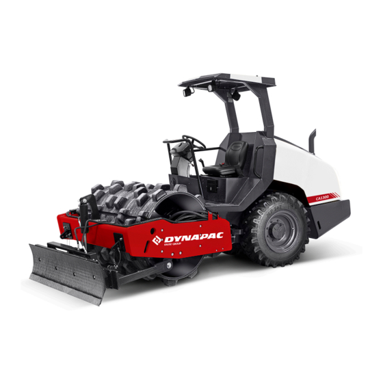
Introduction Introduction The machine CA1300 is a 5 ton vibratory roller intended for compaction work in trenches, on roads and in confined areas in conjunction with refilling work. Intended use CA1300 is available in a D (smooth drum) and PD (padfot) version. -
Page 20: General
Introduction We recommend that the operator reads the We recommend that the operator reads the safety instructions in this manual carefully. safety instructions in this manual carefully. Always follow the safety instructions. Ensure Always follow the safety instructions. Ensure that this manual is always easily accessible. that this manual is always easily accessible. -
Page 21: Ce Marking And Declaration Of Conformity
Introduction The machine must be correctly maintained for maximal performance. The machine should be kept clean so that any leakages, loose bolts and loose connections are discovered at as early a point in time as possible. Inspect the machine every day, before starting. Inspect the entire machine so that any leakages or other faults are detected. - Page 22 Introduction 4812165001.pdf 2023-05-26...
-
Page 23: Safety - General Instructions
Safety - General instructions Safety - General instructions (Also read the safety manual) • • The operator must be familiar with the contents of the OPERATION section The operator must be familiar with the contents of the OPERATION section before starting the roller. before starting the roller. - Page 24 Safety - General instructions • • Hearing protection is recommended if the noise level exceeds 80 dB(A). The Hearing protection is recommended if the noise level exceeds 80 dB(A). The noise level can vary depending on the equipment on the machine and the noise level can vary depending on the equipment on the machine and the surface the machine is being used on.
-
Page 25: Safety - When Operating
Safety - when operating Safety - when operating Prevent persons from entering or remaining in Prevent persons from entering or remaining in the risk zone, i.e. a distance of at least 7 m (23 the risk zone, i.e. a distance of at least 7 m (23 ft) in all directions from operating machines. -
Page 26: Work Driving
Safety - when operating Work driving To exit the cab in an emergency, release the To exit the cab in an emergency, release the hammer on the rear right post and break the rear hammer on the rear right post and break the rear window. -
Page 27: Safety (Optional)
Safety (Optional) Safety (Optional) Strike-off blade The operator must make sure that nobody is The operator must make sure that nobody is in the area of operation while the machine in the area of operation while the machine is in use. is in use. - Page 28 Safety (Optional) 4812165001.pdf 2023-05-26...
-
Page 29: Special Instructions
Special instructions Special instructions Standard lubricants and other recommended oils and fluids Before leaving the factory, the systems and components are filled with the oils and fluids specified in the lubricant specification. These are suitable for ambient temperatures in the range -15°C to +40°C (5°F - 105°F). -
Page 30: High Pressure Cleaning
Special instructions High pressure cleaning Do not spray water directly onto electrical components or the instrument panels. Place a plastic bag over the fuel filler cap and secure with a rubber band. This is to avoid high pressure water entering the vent hole in the filler cap. This could cause malfunctions, such as the blocking of filters. -
Page 31: Fire Extinguisher
Special instructions Fire extinguisher A fire extinguisher can be ordered as an option. Though, different standards are used around the world. If not using the original fire extinguisher, place your extinguisher as in the picture. A 4 kg extinguisher is recommended. Mount it appropriately and make sure it does not create any hazards. -
Page 32: Jump Starting
Special instructions Do not use a quick-charger for charging the Do not use a quick-charger for charging the battery. This may shorten battery life. battery. This may shorten battery life. Jump starting Do not connect the negative cable to the Do not connect the negative cable to the negative terminal on the dead battery. -
Page 33: Technical Specifications
Technical specifications Technical specifications Noise level The noise level is measured in accordance with the operational cycle described in EU The noise level is measured in accordance with the operational cycle described in EU directive 2000/14/EC on machines equipped for the EU market, on soft polymer material directive 2000/14/EC on machines equipped for the EU market, on soft polymer material with vibration switched on and the operator's seat in the transport position. -
Page 34: Dimensions, Side View
Technical specifications Dimensions, side view Dimensions Dimensions Wheelbase, drum and wheel Wheelbase, drum and wheel 1860 1860 Length, standard equipped roller Length, standard equipped roller 3960 3960 Length, with cab Length, with cab 4005 4005 Length, with cab and strike off blade Length, with cab and strike off blade 4286 4286... -
Page 35: Dimensions, Top View
Technical specifications Dimensions, top view Dimensions Dimensions Width, standard equipped roller Width, standard equipped roller 1495 1495 Width, with strike off blade Width, with strike off blade 1550 1550 Overhang, left frame side Overhang, left frame side Overhang, right frame side Overhang, right frame side Turn radius, external Turn radius, external... -
Page 36: Weights And Volumes
Technical specifications Weights and volumes Weights Weights Operating mass, with ROPS Operating mass, with ROPS 4,760 kg 4,760 kg 10,495 lbs 10,495 lbs 5,010 kg 5,010 kg 11,045 lbs 11,045 lbs (EN500) (EN500) Operating mass, with cab (EN500) Operating mass, with cab (EN500) 4,950 kg 4,950 kg 10,915 lbs... -
Page 37: General
Technical specifications Weights Weights - CA1300 (ECO) - CA1300 (ECO) 30 Hz 30 Hz 1,800 rpm 1,800 rpm 30 Hz 30 Hz 1,800 rpm 1,800 rpm Centrifugal force, amplitude Centrifugal force, amplitude 87 kN 87 kN 19,575 lb 19,575 lb 87 kN 87 kN 19,575 lb... -
Page 38: Air Conditioning / Automatic Climate Control (Acc) (Optional)
Technical specifications Bulbs (if mounted) Bulbs (if mounted) Watt Watt Socket Socket Parking lights Parking lights Tire Tire Tire dimensions Tire dimensions Tire pressure Tire pressure Std-type Std-type 12,5-20 12,5-20 200 kPa (2.0 kp/cm²) (29 psi). 200 kPa (2.0 kp/cm²) (29 psi). Tractor type Tractor type 12,5-20... -
Page 39: Tightening Torque
Technical specifications Tightening torque Tightening torque in Nm for oiled or dry bolts tightened with a torque wrench. Metric coarse screw thread, bright galvanized (fzb): PROPERTY CLASS: 8.8, Oiled 8.8, Oiled 8.8, Dry 8.8, Dry 10.9, Oiled 10.9, Oiled 10.9, Dry 10.9, Dry 12.9, Oiled 12.9, Oiled... -
Page 40: Rops - Bolts
Technical specifications ROPS-bolts which are to be torque tightened ROPS-bolts which are to be torque tightened must be dry. must be dry. ROPS - bolts Bolt dimensions : Bolt dimensions : M16 (4700500082) M16 (4700500082) Strength class : Strength class : Tightening torque : Tightening torque : 190 Nm... -
Page 41: Machine Description
Machine description Machine description Diesel engine The machine is equipped with a four-cylinder, water-cooled diesel engine with direct injection. The engine has an overlying camshaft and the cylinder head is shared by all the cylinders. The engine is also equipped with a system for after-treatment of exhaust fumes (DPF Diesel Particle Filter). -
Page 42: Steering System
Machine description Steering system The control system is a mechanical-hydraulic system of the load-sensing type. The control valve on the steering column distributes the flow to the control cylinder at the articulation. The steering angle is proportional to the deflection of the steering wheel. Vibration system The vibration system is a hydrostatic system in which a hydraulic motor drives the eccentric shaft, which... -
Page 43: Identification
Machine description Identification Product and component plates Product plate - Product Identification Number (PIN), model/type designation Product plate - Product Identification Number (PIN), model/type designation Engine plate - Type description, product and serial numbers Engine plate - Type description, product and serial numbers Component plate, rear axle - Product and serial numbers Component plate, rear axle - Product and serial numbers Component plate, drum - Product and serial numbers... -
Page 44: Machine Plate
Machine description Machine plate The machine type plate (1) is attached to the front left side of the frame, beside the steering joint. The plate specifies the manufacturer's name and address, the type of machine, the PIN product identification number (serial number), operating mass, engine power and year of manufacture. -
Page 45: Engine Plates
Machine description Engine plates The engine's type plate (1) is located on top of the cylinder head cover. The plate specifies the type of engine, its serial number and the engine specification. Please specify the engine serial number when ordering spares. Refer also to the engine manual. Fig. -
Page 46: Decals
Machine description Decals Location - decals Diesel fuel Diesel fuel 4811000345 8. 4811000345 8. Warning, Warning, 4700903424 15. Hydraulic fluid 4700903424 15. Hydraulic fluid 4700272373 4700272373 Hot surfaces Hot surfaces level level Warning, Rotating Warning, Rotating 4700903423 9. 4700903423 9. Battery master Battery master 4700904835 16. -
Page 47: Location - Decals, California
Machine description Location - decals, CALIFORNIA Proposition 65 Warning, CALIFORNIA Warning, CALIFORNIA 4812129673 4812129673 Proposition 65 Proposition 65 Fig. Location Safety decals Always make sure that all safety decals are completely legible, and remove dirt or order new decals if they have become illegible. - Page 48 Machine description 4700908229 Warning - Risk of crushing, apply locking device The articulation must be locked when lifting. Read the instruction manual. 4700903424 Warning - Hot surfaces in the engine compartment. Keep your hands at a safe distance. 4700791642 Warning - Starting gas Starting gas is not to be used.
- Page 49 Machine description 4812129673 Warning CALIFORNIA - Proposition 65 2023-05-26 4812165001.pdf...
-
Page 50: Info Decals
Machine description Info decals 1. Diesel fuel 1. Diesel fuel 4. Handbook compartment 4. Handbook compartment 7. Coolant 7. Coolant 4811000345 4811000345 4700903425 4700903425 4700388449 4700388449 9. Master switch 9. Master switch 10. Lifting point 10. Lifting point 11. Hoisting plate 11. -
Page 51: Instruments/Controls
Machine description Instruments/Controls Locations - Instruments and controls Fig. Instruments and control panel Working lights * Working lights * Control lamp, engine tampering Control lamp, engine tampering Driving lights (Low beam) * Driving lights (Low beam) * Switch, parked regeneration Switch, parked regeneration Hazard lights * Hazard lights *... -
Page 52: Locations - Control Panel And Controls
Machine description Locations - Control panel and controls Fig. Control panel Fig. Operator's station Fig. Operator position Strike-off blade Strike-off blade Battery/charging Battery/charging Vibration Vibration On/Off Vibration Vibration On/Off Fuse box Fuse box Low fuel level Low fuel level Instrument cover Instrument cover (For machine equipped with ROPS only). -
Page 53: Function Description
Machine description Function description Designation Designation Symbol Symbol Function Function Working lights, switch Working lights, switch When depressed, the working lights are on When depressed, the working lights are on Driving lights (Low beam), Driving lights (Low beam), When pressed in the upper position,, the low-beam When pressed in the upper position,, the low-beam switch switch... - Page 54 Machine description Designation Designation Symbol Symbol Function Function Strike-off blade, On/Off, Strike-off blade, On/Off, When pressed, the strike-off blade is activated. When pressed, the strike-off blade is activated. switch switch Controls the position of the strike-off blade. Controls the position of the strike-off blade. Vibration, switch (CA1300) Vibration, switch (CA1300) Activates the vibration together with...
- Page 55 Machine description Designation Designation Symbol Symbol Function Function Warning lamp, Warning lamp, If the lamp lights while the engine is running the If the lamp lights while the engine is running the battery charging battery charging alternator is not charging. Stop the engine and alternator is not charging.
-
Page 56: Instruments And Controls, Cab
Machine description Instruments and controls, cab Fig. Cab roof, front Radio/CD Fig. Rear cab post, right-hand side Fig. Cab roof, right side 10. Hammer for emergency escape 4812165001.pdf 2023-05-26... - Page 57 Machine description 2023-05-26 4812165001.pdf...
-
Page 58: Function Description Of Instruments And Controls In The Cab
Machine description Function description of instruments and controls in the cab Designation Designation Symbol Symbol Function Function Heater control Heater control Turn to the right to increase heating. Turn to the right to increase heating. Turn to the left to reduce heating. Turn to the left to reduce heating. -
Page 59: A/C - System Operation
Machine description A/C - System Operation NOTE: When using AC, all windows must be closed for the system to function efficiently. Activating air conditioning To activate the air conditioning, set the ventilation knob to one of the three following positions: •... - Page 60 Machine description Heating mode To activate heating mode, turn the control (1) on the right side of the system clockwise. Heat level is proportional to opening the vent using this command. Fig. Heating mode 1. Control 13. Closed vent 14. Open vent Airflow direction Turn the air vents in any direction and adjust the opening using the flanges.
- Page 61 Machine description Activation of LEDs LEDs (11) will be turned on when the machine door switch is activated, or when the switch (12) is activated. They will be turned off when the switch is activated a second time. Fig. LEDs 11.
-
Page 62: Using The Cab Controls
Machine description Using the cab controls. Defroster For quick de-icing or demisting, make sure that only the outer air vents are open. Turn the heater and fan dial to max. Adjust the nozzle so that it blows on the window to be de-iced, or to remove mist. Heat If the cab is unheated, open the air exhaust located in front of the controls for heating and fan. -
Page 63: Electrical System
Machine description Electrical system Fuses The figure shows the position of the fuses. The table below gives fuse amperage and function. All fuses are flat pin fuses. Fig. Fuse boxes 1. Upper 2. Lower Fuse box, Upper Fuse box, Upper Fuse box, Lower Fuse box, Lower 1. -
Page 64: Fuses In Cab
Machine description Fuses in cab The electrical system in the cab has a separate fuse box located on the front right side of the cab roof. The figure shows fuse amperage and function. Fig. Cab roof fuse box (F7) All fuses are flat pin fuses. 1. -
Page 65: Relays On Machine
Machine description Relays on machine Control column Position lights Position lights Stop lights Stop lights Fig. Relays Control column Engine room Starting Starting Preheating Preheating Fig. Relays Engine room The relays are located behind the plate where the fuse box and switches are located. To access the relays, the plate must be unscrewed. - Page 66 Machine description 4812165001.pdf 2023-05-26...
-
Page 67: Operation
Operation Operation Before starting Master switch - Switching on Remember to carry out daily maintenance. Refer to the maintenance instructions. The battery disconnector is located on the right side of the operator platform. Turn the key (1) to the On position. -
Page 68: Operator's Seat - Adjusting
Operation Operator’s seat - Adjusting Adjust the operator’s seat so that the position is comfortable and so that the controls are within easy reach. The seat can be adjusted lengthways (1). Fig. Operator's seat 1. Length adjustment Driver seat (Equipment status) - Adjustment Adjust the operator’s seat so that the position is comfortable and so that the controls are within easy reach. -
Page 69: Parking Brake
Operation Parking brake Ensure that the parking brake (16) Ensure that the parking brake (16) is definitely switched on. is definitely switched on. Brake is always activated in Neutral position. (automatic 1.5 sec.) The parking brake must be activated to start the machine! Fig. -
Page 70: Operator Position
Operation Operator position If a ROPS (2) (Roll Over Protective Structure) or a cab is fitted to the roller, always wear the seat belt (1) provided and wear a protective helmet. Replace the seat belt (1) if it shows signs of Replace the seat belt (1) if it shows signs of wear or has been subjected to high levels wear or has been subjected to high levels... -
Page 71: Instruments And Lamps - Checking
Operation Instruments and lamps - Checking Make sure that the emergency stop (29) is pulled Make sure that the emergency stop (29) is pulled out. When the roller is in neutral or there is no load out. When the roller is in neutral or there is no load on the operator seat, the automatic brake function on the operator seat, the automatic brake function is engaged. -
Page 72: Working Lights - Adjustment
Operation Working lights - Adjustment Use a ladder for easier access to adjust the working lights. Rear view mirrors - Adjustment Rear view mirrors can be adjusted from the ground, on machines equipped with ROPS. Use a step ladder if adjusting rear view mirrors on a machine equipped with a cabin. -
Page 73: Windscreen Washer Fluid - Checking And Filling
Operation Windscreen washer fluid - Checking and filling Place the roller on a level surface. If necessary, top up the washer fluid in the reservoir (1) behind the operator’s seat. The reservoir holds 2.1 litres (2.2 qts) Fig. Operator's platform 1. -
Page 74: Starting The Engine
Operation Starting the engine To start the roller: To start the roller: - Emergency stop must be inactive - Emergency stop must be inactive - Parking brake must be engaged - Parking brake must be engaged - F/R lever position in Neutral position - F/R lever position in Neutral position - Seated to activate the seat switch - Seated to activate the seat switch... - Page 75 Operation at least 15 minutes. Check while warming the engine that the warning lamps for the oil pressure (21) and charging (26) go out. The warning lamp (23) should remain on. When starting and driving a machine that is cold, When starting and driving a machine that is cold, remember that the hydraulic fluid is also cold and remember that the hydraulic fluid is also cold and...
-
Page 76: Driving
Operation Driving Operating the roller Under no circumstances is the machine to be Under no circumstances is the machine to be operated from the ground. The operator must be operated from the ground. The operator must be seated inside the machine during all operation. seated inside the machine during all operation. -
Page 77: Operation Of Strike-Off Blade (Equipment Status)
Operation Operation of strike-off blade (Equipment status) Before driving, make certain that the blade is in its Before driving, make certain that the blade is in its uppermost position (raised). Inspect the condition uppermost position (raised). Inspect the condition of the ground before using the blade. of the ground before using the blade. - Page 78 Operation If the machine runs a lot on partial load, start-stop and at low engine temperatures, etc., a parked regen (regeneration) may need to be performed. This is indicated by the lamp for Parked Regen Requested (5) is required, comes on, the indicator lamp (8) flashes and there is a signal from the buzzer.
-
Page 79: Tampering Of Dpf
Operation If the request for a parked regen (5, 11) is If the request for a parked regen (5, 11) is ignored, error codes will be set and the engine ignored, error codes will be set and the engine power will be reduced. If the indicators continue power will be reduced. -
Page 80: High Ash Levels
Operation High ash levels The ash that forms in the DPF cannot be regenerated, but remains in the DPF. The regeneration warning lamp (5) lights up. Yellow warning lamp (8) flashes continuously and error code is displayed. Operation is still possible. The red warning lamp (7) flashes continuously and an error code is displayed. -
Page 81: Braking
Operation Braking Service brake Move the forward/reverse lever (32) to the neutral position to stop the roller. Always press down the parking brake (16), before leaving the operator platform. If the forward/reverse lever is moved quickly (forwards or backwards) toward/past neutral, the system switches to a rapid braking Mode and the machine stops. -
Page 82: Reserve Brake
Operation Reserve brake Braking is normally activated using the forward/reverse lever. The hydrostatic transmission brakes the roller when the lever is moved towards the neutral position. There is also a brake in the drum motor and rear axle that acts as an emergency brake during operation. When emergency braking, engage the parking When emergency braking, engage the parking brake (16), hold the steering wheel firmly and... -
Page 83: Switching Off
Operation Switching off Check instruments and warning lamps to see if any faults are indicated. Switch off all lights and other electrical functions. Turn the starter switch (30) to the left to switched off position 1. At the end of the shift, lower the instrument cover (6) and lock it. -
Page 84: Master Switch
Operation Master switch Before leaving the roller for the day, switch the master switch (1) to the disconnected position and remove the handle. This prevents the battery from discharging and makes it difficult for unauthorised persons to start and operate the machine. -
Page 85: Long-Term Parking
Long-term parking Long-term parking The following instructions should be followed The following instructions should be followed when long term parking (more than one month). when long term parking (more than one month). These measures apply when parking for a period of up to 6 months. -
Page 86: Steering Cylinder, Hinges, Etc
Long-term parking Steering cylinder, hinges, etc. Grease the steering cylinder piston with conservation grease. Grease the hinges on the doors to the engine compartment. Grease both ends of the forward/reverse control (bright parts) (see under the heading ‘Every 500 hours of operation’). Tires Check that the tire pressure is: 200 kPa (2.0 kp/cm... -
Page 87: Miscellaneous
Miscellaneous Miscellaneous Lifting Locking the articulation Articulation must be locked to prevent Articulation must be locked to prevent inadvertent turning before lifting the roller. inadvertent turning before lifting the roller. Turn the steering wheel to the straight ahead position. Enable the parking brake (31). Pull out the locking pin (2) fitted with a wire, and pull up the stud (3). -
Page 88: Unlocking The Articulation
Miscellaneous Unlocking the articulation Remember to unlock the articulation Remember to unlock the articulation before operating. before operating. Fold the locking arm (1) back and secure it in the locking lug (4) with the stud (3). Insert the locking pin (2) fitted with a wire, to secure the stud (3). -
Page 89: Rear Axle Brake
Miscellaneous Rear axle brake The two brake release screws (1) are located on the front and back of the rear axle. Fig. Rear axle 1. Brake release screw (x2). Brake disengagement Unscrew the brake release screws (1) and remove the stop washers (3). -
Page 90: Releasing The Drum Brake
Miscellaneous Releasing the drum brake Drum motor brake Remove the drum brake centre plug (2), which is accessible through the centre hole (1) in the left frame side. Fig. Left frame side 1. Center hole 2. Center plug Screw in the bolt (3) all the way as shown in the figure. Now screw in the nut (4) so that it is flush with the washer, and then an additional 0,75 - 1 turns, holding the screw in place (3). -
Page 91: Towing
Miscellaneous Towing A towing bar must be used when towing, as the A towing bar must be used when towing, as the roller has no brakes and can only be slowed and roller has no brakes and can only be slowed and stopped by the vehicle towing the roller. -
Page 92: Securing
Miscellaneous Securing Securing CA1300 vibratory roller from Dynapac loaded facing forwards on a trailer for road and Baltic Sea transport (Sea area A). Roller loaded facing forwards Direct of travel 1 - 3 = double lashings, i.e. one lashing with two parts secured to two different lashing mounts, 1 - 3 = double lashings, i.e. - Page 93 Miscellaneous Load carrier Load carrier Load the roller in the centre of the platform from the sides (± 5 cm) and facing forwards. Load the roller in the centre of the platform from the sides (± 5 cm) and facing forwards. The parking brake is applied and in good working condition.
- Page 94 Miscellaneous Securing Securing CA1300 vibratory roller from Dynapac loaded facing forwards on a trailer for road and North Sea transport (Sea area B). Roller loaded facing forwards Direct of travel 1 - 3 = double lashings, i.e. one lashing with two parts secured to two different lashing mounts, 1 - 3 = double lashings, i.e.
- Page 95 Miscellaneous Load carrier Load carrier Load the roller in the centre of the platform from the sides (± 5 cm) and facing forwards. Load the roller in the centre of the platform from the sides (± 5 cm) and facing forwards. The parking brake is applied and in good working condition.
- Page 96 Operating instructions - Summary 4812165001.pdf 2023-05-26...
-
Page 97: Operating Instructions - Summary
Operating instructions - Summary Operating instructions - Summary Follow the SAFETY INSTRUCTIONS specified in the Safety Manual. Follow the SAFETY INSTRUCTIONS specified in the Safety Manual. Make sure that all instructions in the MAINTENANCE section are followed. Make sure that all instructions in the MAINTENANCE section are followed. Turn the battery disconnector to ON and ensure that the articulated joint lock is Turn the battery disconnector to ON and ensure that the articulated joint lock is open. - Page 98 Operating instructions - Summary 4812165001.pdf 2023-05-26...
-
Page 99: Preventive Maintenance
Preventive maintenance Preventive maintenance Complete maintenance is necessary for the machine to function satisfactorily and at the lowest possible cost. The Maintenance section includes the periodic maintenance that must be carried out on the machine. The recommended maintenance intervals assume that the machine is used in a normal environment and working conditions. - Page 100 Preventive maintenance CALIFORNIA Proposition 65 Decal and location of decal shown in section Machine description. 4812165001.pdf 2023-05-26...
-
Page 101: Maintenance - Lubricants And Symbols
Maintenance - Lubricants and symbols Maintenance - Lubricants and symbols Always use high-quality lubricants and the Always use high-quality lubricants and the amounts recommended. Too much grease or amounts recommended. Too much grease or oil can cause overheating, oil can cause overheating, resulting in rapid wear. - Page 102 Maintenance - Lubricants and symbols ENGINE OIL ENGINE OIL Air temperature -15°C - +50°C Air temperature -15°C - +50°C Dynapac Engine Oil Dynapac Engine Oil P/N 4812161855 (5 liters) P/N 4812161855 (5 liters) (5°F-122°F) (5°F-122°F) P/N 4812161856 (20 liters) P/N 4812161856 (20 liters) HYDRAULIC FLUID HYDRAULIC FLUID Air temperature -15°C - +50°C...
-
Page 103: Maintenance Symbols
Maintenance - Lubricants and symbols Fluid volumes Fluid volumes Oil in hydraulic system Oil in hydraulic system 42.0 liters 42.0 liters 11.1 gal 11.1 gal Diesel engine Diesel engine - Lubricating oil - Lubricating oil 10,5 liters 10,5 liters 11 qts 11 qts (incl. - Page 104 Maintenance - Lubricants and symbols 4812165001.pdf 2023-05-26...
-
Page 105: Maintenance - Maintenance Schedule
Maintenance - Maintenance schedule Maintenance - Maintenance schedule Service and maintenance points 7 10 22,23,24 Fig. Service and maintenance points Radiator grille Radiator grille Scraper Scraper Engine suspension, 4 pcs. Engine suspension, 4 pcs. Oil level, diesel engine Oil level, diesel engine Drum oil, level plug, 1 pc. -
Page 106: General
Maintenance - Maintenance schedule General Periodic maintenance should be carried out after the number of hours specified. Use the daily, weekly etc. periods where number of hours cannot be used. Remove all dirt before filling, when checking Remove all dirt before filling, when checking oils and fuel and when lubricating using oil oils and fuel and when lubricating using oil or grease. -
Page 107: After The First 50 Hours Of Operation
Maintenance - Maintenance schedule After the FIRST 50 hours of operation Refer to the contents to find the page number of the sections referred to ! Pos. in Pos. in Action Action Comment Comment Replacing the hydraulic oil filter Replacing the hydraulic oil filter Checking that wheel-nuts are tightened Checking that wheel-nuts are tightened Check the tire pressure... -
Page 108: Every 500 / 2500 / 3500 / 4500 / 5500 / 6500 / 9500 Hours Of Operation
Maintenance - Maintenance schedule Every 500 / 2500 / 3500 / 4500 / 5500 / 6500 / 9500 hours of operation Refer to the contents to find the page number of the sections referred to ! Pos. in Pos. in Action Action Comment... -
Page 109: Every 1000 Hours Of Operation
Maintenance - Maintenance schedule Every 1000 hours of operation Refer to the contents to find the page number of the sections referred to ! Pos. in Pos. in Action Action Comment Comment Checking the battery Checking the battery Draining the water separator Draining the water separator Changing the oil in rear axle differential Changing the oil in rear axle differential... -
Page 110: Every 1500 Hours Of Operation
Maintenance - Maintenance schedule Every 1500 hours of operation Refer to the contents to find the page number of the sections referred to ! Pos. in Pos. in Action Action Comment Comment Checking the battery Checking the battery Drain the water separator Drain the water separator Checking the oil level in rear axle differential Checking the oil level in rear axle differential... -
Page 111: Every 2000 / 4000 / 8000 Hours Of Operation
Maintenance - Maintenance schedule Every 2000 / 4000 / 8000 hours of operation Refer to the contents to find the page number of the sections referred to ! Pos. in Pos. in Action Action Comment Comment Checking the battery Checking the battery Draining the water separator Draining the water separator Changing the oil in rear axle differential... - Page 112 Maintenance - Maintenance schedule Pos. in Pos. in Action Action Comment Comment Checking the battery Checking the battery Draining the water separator Draining the water separator Changing the oil in rear axle differential Changing the oil in rear axle differential Changing the oil in rear axle pinion housing Changing the oil in rear axle pinion housing Change oil in rear axle planetary gears...
- Page 113 Maintenance - Maintenance schedule Pos. in Pos. in Action Action Comment Comment Checking the throttle body intake Checking the throttle body intake Contact your local Yanmar Contact your local Yanmar representative representative Checking and cleaning the injector Checking and cleaning the injector 2023-05-26 4812165001.pdf...
-
Page 114: Every 6,000 Hours Of Operation
Maintenance - Maintenance schedule Every 6,000 hours of operation Refer to the contents to find the page number of the sections referred to ! Pos. in Pos. in Action Action Comment Comment Checking the battery Checking the battery Draining the water separator Draining the water separator Changing the oil in rear axle differential Changing the oil in rear axle differential... -
Page 115: Every 9000 Hours Of Operation
Maintenance - Maintenance schedule Every 9000 hours of operation Refer to the contents to find the page number of the sections referred to ! Pos. in Pos. in Action Action Comment Comment Checking the battery Checking the battery Draining the water separator Draining the water separator Replacing oil level in rear axle differential Replacing oil level in rear axle differential... -
Page 116: Every 24Th Month (Every Other Year)
Maintenance - Maintenance schedule Every 24th month (Every other year) Refer to the contents to find the page number of the sections referred to ! Pos. Pos. Action Action Comment Comment in fig in fig Replacing the coolant Replacing the coolant Checking cooler hoses and hose clamps Checking cooler hoses and hose clamps Replace when necessary... -
Page 117: Service - Checklist
Maintenance - Maintenance schedule Service - Checklist 2023-05-26 4812165001.pdf... - Page 118 Maintenance - Maintenance schedule 4812165001.pdf 2023-05-26...
-
Page 119: Maintenance, 10H
Maintenance, 10h Maintenance, 10h Every 10 hours of operation (Daily) Scrapers - Check, adjustment It is important to consider movement of the drum It is important to consider movement of the drum when the machine turns, i.e., the scrapers can be when the machine turns, i.e., the scrapers can be damaged or wear of the drum may increase if damaged or wear of the drum may increase if... -
Page 120: Scrapers, Pad-Drum
Maintenance, 10h Scrapers, Pad-drum Undo the screws (2), washers (3) and nuts (4) from the scraper bracket (5). Adjust the scraper blade to 25 mm (1.0 in) and centre each scraper tooth (1) between the pads when fitting. Tighten the screws (2), washers (3) and nuts (4) on the scraper bracket (5). -
Page 121: Coolant Level - Check
Maintenance, 10h Coolant level - Check Place the roller on a level surface. Check that level of the coolant is between the max. and min. marks. Observe great caution if the radiator cap has to be Observe great caution if the radiator cap has to be opened while the engine is hot. -
Page 122: Windscreen Washer Fluid - Checking And Filling
Maintenance, 10h Windscreen washer fluid - Checking and filling Place the roller on a level surface. If necessary, top up the washer fluid in the reservoir (1) behind the operator’s seat. The reservoir holds 2.1 litres (2.2 qts) Fig. Operator's platform 1. -
Page 123: Fuel Tank - Filling
Maintenance, 10h Fuel tank - Filling Refuel daily with diesel fuel up to the lower edge of the filler pipe (1). Follow the engine manufacturer's specification with regard to the quality of diesel fuel. Stop the diesel engine. Short-circuit (press) the Stop the diesel engine. -
Page 124: Air Cleaner
Maintenance, 10h Air cleaner Check - Replacement of main filter Replace the air cleaner's main filter when the Replace the air cleaner's main filter when the indicator shows red. The indicator is mounted on indicator shows red. The indicator is mounted on the air cleaner's connecting pipe. -
Page 125: Air Cleaner - Cleaning
Maintenance, 10h Air cleaner - Cleaning Wipe clean the inside of the cover (2) and the filter housing (5). See the previous illustration. Wipe clean on both sides Wipe also both surfaces for the outlet pipe. of the outlet pipe. See adjacent figure. -
Page 126: Brakes - Check
Maintenance, 10h Brakes - Check Check operation of the brakes as follows: Check operation of the brakes as follows: Checking the emergency stop Drive the roller slowly forward. Hold the steering wheel firmly and brace yourself for a sudden stop. Press the emergency stop (1). -
Page 127: Maintenance, First 50H
Maintenance, first 50h Maintenance, first 50h Park the roller on a level surface. Park the roller on a level surface. The engine must be switched off and the The engine must be switched off and the parking brake activated when checking or parking brake activated when checking or adjusting the roller, unless otherwise specified. - Page 128 Maintenance, first 50h Carefully clean round the filter. Remove the oil filter (1) and hand in to an Remove the oil filter (1) and hand in to an environment-friendly waste disposal station. environment-friendly waste disposal station. This is a disposable filter and cannot be cleaned. This is a disposable filter and cannot be cleaned.
-
Page 129: Tires - Air Pressure - Wheel Nuts - Tightening
Maintenance, first 50h Tires - Air pressure - Wheel nuts - Tightening Check the tire pressures using a pressure gauge. If the tires are filled with fluid, the air valve (1) must be in the "12 o'clock" position during pumping. Recommended pressure: See Technical Specifications. -
Page 130: Replacing Belts/Checking The Belt Tension
Maintenance, first 50h Replacing belts/Checking the belt tension Exercise care to stop the engine and remove Exercise care to stop the engine and remove the key before checking the belt tension. the key before checking the belt tension. To check the belt tension, apply a moderate pressure with your thumb on the belt (between the belt pulleys on the alternator and crankshaft). -
Page 131: Maintenance - 50H
Maintenance - 50h Maintenance - 50h Every 50 hours of operation (Weekly) Park the roller on a level surface. Park the roller on a level surface. The engine must be switched off and the The engine must be switched off and the parking brake activated when checking or parking brake activated when checking or adjusting the roller, unless otherwise specified. -
Page 132: Pre-Fuel Filter - Draining
Maintenance - 50h Pre-fuel filter - Draining Close the fuel valve (4) by turning it to position 3. Open the drain valve (5) at the bottom of the water separator. Drain any water. If no water comes out, loosen the air vent screw (6) at the top of the water separator by turning it counterclockwise 2 - 3 turns. -
Page 133: Maintenance Measures - 250 H
Maintenance measures - 250 h Maintenance measures - 250 h Every 250/750/1250/1750..hours of operation (every 3 months) Park the roller on a level surface. Park the roller on a level surface. The engine must be switched off and the The engine must be switched off and the parking brake activated when checking or parking brake activated when checking or... -
Page 134: Rear Axle Differential - Check Oil Level
Maintenance measures - 250 h Rear axle differential - Check oil level Never work under the roller when Never work under the roller when the engine is running. the engine is running. Park on a level surface. Park on a level surface. Block the wheels securely. -
Page 135: Rear Axle Planetary Gears - Check Oil Level
Maintenance measures - 250 h Rear axle planetary gears - Check oil level Position the roller with the plug in the planetary gear (1) in the "9 o'clock" position. Wipe clean and remove the level plug (1) and check that the oil level reaches the lower edge of the plug hole. -
Page 136: Coolers
Maintenance measures - 250 h If filling is necessary, loosen the filler plug (1) and fill. Do not overfill with oil - risk of overheating. Do not overfill with oil - risk of overheating. Be sure to use only Be sure to use only Dynapac gear oil 300 in the roller. -
Page 137: Replacing Belts/Checking The Belt Tension
Maintenance measures - 250 h Replacing belts/Checking the belt tension Exercise care to stop the engine and remove Exercise care to stop the engine and remove the key before checking the belt tension. the key before checking the belt tension. To check the belt tension, apply a moderate pressure with your thumb on the belt (between the belt pulleys on the alternator and crankshaft). -
Page 138: Bolted Joints - Checking Tightening Torque
Maintenance measures - 250 h Bolted joints - Checking tightening torque Check that all the bolts for the suspension of the engine and the drive unit are tightened. See under Specifications - tightening torque. Check the bolted joint between the motor and the pump drive, and that all the hydraulic components are tightened to the set tightening torque. -
Page 139: Fuel Tank - Draining (Equipment Status)
Maintenance measures - 250 h Fuel tank - Draining (Equipment status) Water and sediment in the fuel tank are drained out via the drain plug (1) in the bottom of the fuel tank. Be very careful during draining. Do not drop the Be very careful during draining. - Page 140 Maintenance measures - 250 h 4812165001.pdf 2023-05-26...
-
Page 141: Maintenance Measures - 500 / 2500 / 3500 / 4500 / 5500 / 6500 / 9500H
Maintenance measures - 500 / 2500 / 3500 / 4500 / 5500 / 6500 / 9500h Maintenance measures - 500 / 2500 / 3500 / 4500 / 5500 / 6500 / 9500h Every 500 / 2500 / 3500 / 4500 / 5500 / 6500 / 9500 hours of operation Park the roller on a level surface. -
Page 142: Rear Axle Differential - Check Oil Level
Maintenance measures - 500 / 2500 / 3500 / 4500 / 5500 / 6500 / 9500h Rear axle differential - Check oil level Never work under the roller when Never work under the roller when the engine is running. the engine is running. Park on a level surface. -
Page 143: Rear Axle Planetary Gears - Check Oil Level
Maintenance measures - 500 / 2500 / 3500 / 4500 / 5500 / 6500 / 9500h Rear axle planetary gears - Check oil level Position the roller with the plug in the planetary gear (1) in the "9 o'clock" position. Wipe clean and remove the level plug (1) and check that the oil level reaches the lower edge of the plug hole. -
Page 144: Coolers
Maintenance measures - 500 / 2500 / 3500 / 4500 / 5500 / 6500 / 9500h If filling is necessary, loosen the filler plug (1) and fill. Do not overfill with oil - risk of overheating. Do not overfill with oil - risk of overheating. Be sure to use only Be sure to use only Dynapac gear oil 300 in the roller. -
Page 145: Replacing Belts/Checking The Belt Tension
Maintenance measures - 500 / 2500 / 3500 / 4500 / 5500 / 6500 / 9500h Replacing belts/Checking the belt tension Exercise care to stop the engine and remove Exercise care to stop the engine and remove the key before checking the belt tension. the key before checking the belt tension. -
Page 146: Bolted Joints - Checking Tightening Torque
Maintenance measures - 500 / 2500 / 3500 / 4500 / 5500 / 6500 / 9500h Bolted joints - Checking tightening torque Check that all the bolts for the suspension of the engine and the drive unit are tightened. See under Specifications - tightening torque. Check the bolted joint between the motor and the pump drive, and that all the hydraulic components are tightened to the set tightening torque. -
Page 147: Fuel Tank - Draining (Equipment Status)
Maintenance measures - 500 / 2500 / 3500 / 4500 / 5500 / 6500 / 9500h Fuel tank - Draining (Equipment status) Water and sediment in the fuel tank are drained out via the drain plug (1) in the bottom of the fuel tank. Be very careful during draining. -
Page 148: The Engine Fuel Pre-Filter - Replacement/Cleaning
Maintenance measures - 500 / 2500 / 3500 / 4500 / 5500 / 6500 / 9500h The engine fuel pre-filter - replacement/cleaning Place a container underneath to collect fuel that runs out when the filter is released. Close the fuel valve (4) by turning it to position 3. Loosen the drain valve (4) and drain fuel and desposits. -
Page 149: The Engine Fuel Filter - Replacement/Cleaning
Maintenance measures - 500 / 2500 / 3500 / 4500 / 5500 / 6500 / 9500h The engine fuel filter - replacement/cleaning Place a container underneath to collect fuel that runs out when the filter is released. Close the fuel valve of the water separator. Loosen and unscrew the fuel filter (1). -
Page 150: Diesel Engine - Oil- And Filter Change
Maintenance measures - 500 / 2500 / 3500 / 4500 / 5500 / 6500 / 9500h Diesel engine - Oil- and Filter change Changing the engine oil Remove one of the oil filler caps (3) to vent the engine crankcase and allow the engine lubricating oil to drain more easily. - Page 151 Maintenance measures - 500 / 2500 / 3500 / 4500 / 5500 / 6500 / 9500h Warm up the engine by running it for 5 minutes and check for any engine lubricating oil leaks. When the engine is warm, turn off the engine and let it cool for 10 minutes.
-
Page 152: Forward/Reverse Controls And Joints - Check And Lubrication
Maintenance measures - 500 / 2500 / 3500 / 4500 / 5500 / 6500 / 9500h Forward/Reverse controls and joints - Check and lubrication Accessing the machine fitted with ROPS The easiest way to access the forward/reverse lever pivot points is via the operator's manual pocket on the right-hand side of the driver's seat. -
Page 153: Hood, Hinges - Lubrication
Maintenance measures - 500 / 2500 / 3500 / 4500 / 5500 / 6500 / 9500h If the forward/reverse lever still is stiff after the above adjustments, lubricate the other end of the control cable with a few drops of oil. The cable is located on the top of the propulsion pump. -
Page 154: Cab, Hinges - Lubrication
Maintenance measures - 500 / 2500 / 3500 / 4500 / 5500 / 6500 / 9500h Cab, hinges - Lubrication Lubricate the hinges (2) on the cab doors with grease. See lubricant specification. Fig. Cab 2. Hinge, cab Air conditioning (Optional) Fresh air filter - Change Use a step ladder to reach the filter (1). -
Page 155: Air Filter Indicator - Resetting
Maintenance measures - 500 / 2500 / 3500 / 4500 / 5500 / 6500 / 9500h Air filter indicator - Resetting The air filter indicator is located on the filter, or in its immediate vicinity. The air filter indicator must be reset after replacing the air filter. -
Page 156: Air Conditioning (Optional) - Check
Maintenance measures - 500 / 2500 / 3500 / 4500 / 5500 / 6500 / 9500h Air conditioning (Optional) - Check If cooling capacity is noticeably impaired, clean the condenser element (1) located in front of the radiator in the engine compartment (see Radiator, Check - Cleaning). -
Page 157: Maintenance - 1000H
Maintenance - 1000h Maintenance - 1000h Performed after 1000 operating hours (each year) Park the roller on a level surface. Park the roller on a level surface. The engine must be switched off and the The engine must be switched off and the parking brake activated when checking or parking brake activated when checking or adjusting the roller, unless otherwise specified. -
Page 158: Rear Axle Differential - Oil Change
Maintenance - 1000h Rear axle differential - Oil change Never work under the roller when the engine Never work under the roller when the engine is running. Park on a level surface. is running. Park on a level surface. Block the wheels securely. Block the wheels securely. -
Page 159: Rear Axle Planetary Gear - Oil Change
Maintenance - 1000h Rear axle planetary gear - Oil change Position the roller with the plug in the planetary gear at its lowest position, 1. Wipe clean, unscrew plug (1) and drain the oil into a container. The volume is approx. 0.9 liters (0.95 qts)/side. -
Page 160: Drum - Checking The Oil Level
Maintenance - 1000h Drum - Checking the oil level Position the roller on a flat surface with the groove (1) on the inside of the drum aligned with the top of the drum frame. Release the level plug (4) and unscrew until oil starts to run out through the plug hole. -
Page 161: Coolers
Maintenance - 1000h Coolers Checking - Cleaning Make sure that the air flow through the coolers (1) and (2) is unobstructed. Dirty coolers are blown clean with compressed air or washed clean using a high-pressure water cleaner. Blow air or direct water through the cooler in the opposite direction to that of the cooling air. -
Page 162: Replacing Belts/Checking The Belt Tension
Maintenance - 1000h Replacing belts/Checking the belt tension Exercise care to stop the engine and remove Exercise care to stop the engine and remove the key before checking the belt tension. the key before checking the belt tension. To check the belt tension, apply a moderate pressure with your thumb on the belt (between the belt pulleys on the alternator and crankshaft). -
Page 163: Bolted Joints - Checking Tightening Torque
Maintenance - 1000h Bolted joints - Checking tightening torque Check that all the bolts for the suspension of the engine and the drive unit are tightened. See under Specifications - tightening torque. Check the bolted joint between the motor and the pump drive, and that all the hydraulic components are tightened to the set tightening torque. -
Page 164: Fuel Tank - Draining (Equipment Status)
Maintenance - 1000h Fuel tank - Draining (Equipment status) Water and sediment in the fuel tank are drained out via the drain plug (1) in the bottom of the fuel tank. Be very careful during draining. Do not drop the Be very careful during draining. -
Page 165: Hydraulic Filter - Replacement
Maintenance - 1000h Hydraulic filter - Replacement Release the filler cap/breather filter (1) so that any overpressure inside the reservoir is eliminated. Check that the breather filter (1) is not clogged. Air should be able to pass freely through the cap in both directions. - Page 166 Maintenance - 1000h Carefully clean round the filter. Remove the oil filter (1) and hand in to an Remove the oil filter (1) and hand in to an environment-friendly waste disposal station. environment-friendly waste disposal station. This is a disposable filter and cannot be cleaned. This is a disposable filter and cannot be cleaned.
-
Page 167: Pre-Fuel Filter - Draining
Maintenance - 1000h Pre-fuel filter - Draining Close the fuel valve (4) by turning it to position 3. Open the drain valve (5) at the bottom of the water separator. Drain any water. If no water comes out, loosen the air vent screw (6) at the top of the water separator by turning it counterclockwise 2 - 3 turns. -
Page 168: The Engine Fuel Pre-Filter - Replacement/Cleaning
Maintenance - 1000h The engine fuel pre-filter - replacement/cleaning Place a container underneath to collect fuel that runs out when the filter is released. Close the fuel valve (4) by turning it to position 3. Loosen the drain valve (4) and drain fuel and desposits. -
Page 169: The Engine Fuel Filter - Replacement/Cleaning
Maintenance - 1000h The engine fuel filter - replacement/cleaning Place a container underneath to collect fuel that runs out when the filter is released. Close the fuel valve of the water separator. Loosen and unscrew the fuel filter (1). Use a filter wrench to turn the filter to the left. When removing the fuel filter, carefully hold it to prevent the fuel from spilling. -
Page 170: Diesel Engine - Oil- And Filter Change
Maintenance - 1000h Diesel engine - Oil- and Filter change Changing the engine oil Remove one of the oil filler caps (3) to vent the engine crankcase and allow the engine lubricating oil to drain more easily. Place a receptacle that holds 15 liters (4 gal) under the drain plug. - Page 171 Maintenance - 1000h Warm up the engine by running it for 5 minutes and check for any engine lubricating oil leaks. When the engine is warm, turn off the engine and let it cool for 10 minutes. Recheck the engine oil level. Add engine oil as needed until the level is between the upper and lower lines shown on the dipstick.
-
Page 172: Forward/Reverse Controls And Joints - Check And Lubrication
Maintenance - 1000h Forward/Reverse controls and joints - Check and lubrication Accessing the machine fitted with ROPS The easiest way to access the forward/reverse lever pivot points is via the operator's manual pocket on the right-hand side of the driver's seat. Fig. -
Page 173: Hood, Hinges - Lubrication
Maintenance - 1000h If the forward/reverse lever still is stiff after the above adjustments, lubricate the other end of the control cable with a few drops of oil. The cable is located on the top of the propulsion pump. Fig. Engine compartment 1. -
Page 174: Cab, Hinges - Lubrication
Maintenance - 1000h Cab, hinges - Lubrication Lubricate the hinges (2) on the cab doors with grease. See lubricant specification. Fig. Cab 2. Hinge, cab Air conditioning (Optional) Fresh air filter - Change Use a step ladder to reach the filter (1). The filter Use a step ladder to reach the filter (1). -
Page 175: Air Filter Indicator - Resetting
Maintenance - 1000h Air filter indicator - Resetting The air filter indicator is located on the filter, or in its immediate vicinity. The air filter indicator must be reset after replacing the air filter. Fig. Indicator Press the "button" (1) on the top of the indicator 1. -
Page 176: Air Conditioning (Optional) - Check
Maintenance - 1000h Air conditioning (Optional) - Check If cooling capacity is noticeably impaired, clean the condenser element (1) located in front of the radiator in the engine compartment (see Radiator, Check - Cleaning). Also clean the cooling unit in the cab. See under the heading 2000 hours, air conditioning - overhaul. -
Page 177: Maintenance Measures - 1500 H
Maintenance measures - 1500 h Maintenance measures - 1500 h Park the roller on a level surface. Park the roller on a level surface. The engine must be switched off and the The engine must be switched off and the parking brake activated when checking or parking brake activated when checking or adjusting the roller, unless otherwise specified. -
Page 178: Rear Axle Differential - Check Oil Level
Maintenance measures - 1500 h Rear axle differential - Check oil level Never work under the roller when Never work under the roller when the engine is running. the engine is running. Park on a level surface. Park on a level surface. Block the wheels securely. -
Page 179: Rear Axle Planetary Gears - Check Oil Level
Maintenance measures - 1500 h Rear axle planetary gears - Check oil level Position the roller with the plug in the planetary gear (1) in the "9 o'clock" position. Wipe clean and remove the level plug (1) and check that the oil level reaches the lower edge of the plug hole. -
Page 180: Coolers
Maintenance measures - 1500 h If filling is necessary, loosen the filler plug (1) and fill. Do not overfill with oil - risk of overheating. Do not overfill with oil - risk of overheating. Be sure to use only Be sure to use only Dynapac gear oil 300 in the roller. -
Page 181: Replacing Belts/Checking The Belt Tension
Maintenance measures - 1500 h Replacing belts/Checking the belt tension Exercise care to stop the engine and remove Exercise care to stop the engine and remove the key before checking the belt tension. the key before checking the belt tension. To check the belt tension, apply a moderate pressure with your thumb on the belt (between the belt pulleys on the alternator and crankshaft). -
Page 182: Bolted Joints - Checking Tightening Torque
Maintenance measures - 1500 h Bolted joints - Checking tightening torque Check that all the bolts for the suspension of the engine and the drive unit are tightened. See under Specifications - tightening torque. Check the bolted joint between the motor and the pump drive, and that all the hydraulic components are tightened to the set tightening torque. -
Page 183: Fuel Tank - Draining (Equipment Status)
Maintenance measures - 1500 h Fuel tank - Draining (Equipment status) Water and sediment in the fuel tank are drained out via the drain plug (1) in the bottom of the fuel tank. Be very careful during draining. Do not drop the Be very careful during draining. -
Page 184: Pre-Fuel Filter - Draining
Maintenance measures - 1500 h Pre-fuel filter - Draining Close the fuel valve (4) by turning it to position 3. Open the drain valve (5) at the bottom of the water separator. Drain any water. If no water comes out, loosen the air vent screw (6) at the top of the water separator by turning it counterclockwise 2 - 3 turns. -
Page 185: The Engine Fuel Pre-Filter - Replacement/Cleaning
Maintenance measures - 1500 h The engine fuel pre-filter - replacement/cleaning Place a container underneath to collect fuel that runs out when the filter is released. Close the fuel valve (4) by turning it to position 3. Loosen the drain valve (4) and drain fuel and desposits. -
Page 186: The Engine Fuel Filter - Replacement/Cleaning
Maintenance measures - 1500 h The engine fuel filter - replacement/cleaning Place a container underneath to collect fuel that runs out when the filter is released. Close the fuel valve of the water separator. Loosen and unscrew the fuel filter (1). Use a filter wrench to turn the filter to the left. -
Page 187: Diesel Engine - Oil- And Filter Change
Maintenance measures - 1500 h Diesel engine - Oil- and Filter change Changing the engine oil Remove one of the oil filler caps (3) to vent the engine crankcase and allow the engine lubricating oil to drain more easily. Place a receptacle that holds 15 liters (4 gal) under the drain plug. - Page 188 Maintenance measures - 1500 h Warm up the engine by running it for 5 minutes and check for any engine lubricating oil leaks. When the engine is warm, turn off the engine and let it cool for 10 minutes. Recheck the engine oil level. Add engine oil as needed until the level is between the upper and lower lines shown on the dipstick.
-
Page 189: Forward/Reverse Controls And Joints - Check And Lubrication
Maintenance measures - 1500 h Forward/Reverse controls and joints - Check and lubrication Accessing the machine fitted with ROPS The easiest way to access the forward/reverse lever pivot points is via the operator's manual pocket on the right-hand side of the driver's seat. Fig. -
Page 190: Hood, Hinges - Lubrication
Maintenance measures - 1500 h If the forward/reverse lever still is stiff after the above adjustments, lubricate the other end of the control cable with a few drops of oil. The cable is located on the top of the propulsion pump. Fig. -
Page 191: Cab, Hinges - Lubrication
Maintenance measures - 1500 h Cab, hinges - Lubrication Lubricate the hinges (2) on the cab doors with grease. See lubricant specification. Fig. Cab 2. Hinge, cab Air conditioning (Optional) Fresh air filter - Change Use a step ladder to reach the filter (1). The filter Use a step ladder to reach the filter (1). -
Page 192: Air Filter Indicator - Resetting
Maintenance measures - 1500 h Air filter indicator - Resetting The air filter indicator is located on the filter, or in its immediate vicinity. The air filter indicator must be reset after replacing the air filter. Fig. Indicator Press the "button" (1) on the top of the indicator 1. -
Page 193: Air Conditioning (Optional) - Check
Maintenance measures - 1500 h Air conditioning (Optional) - Check If cooling capacity is noticeably impaired, clean the condenser element (1) located in front of the radiator in the engine compartment (see Radiator, Check - Cleaning). Also clean the cooling unit in the cab. See under the heading 2000 hours, air conditioning - overhaul. - Page 194 Maintenance measures - 1500 h 4812165001.pdf 2023-05-26...
-
Page 195: Maintenance - 2000 / 4000 / 8000 H
Maintenance - 2000 / 4000 / 8000 h Maintenance - 2000 / 4000 / 8000 h Performed after 2000 / 4000 / 8000 operating hours Park the roller on a level surface. Park the roller on a level surface. The engine must be switched off and the The engine must be switched off and the parking brake activated when checking or parking brake activated when checking or... -
Page 196: Rear Axle Differential - Oil Change
Maintenance - 2000 / 4000 / 8000 h Rear axle differential - Oil change Never work under the roller when the engine Never work under the roller when the engine is running. Park on a level surface. is running. Park on a level surface. Block the wheels securely. -
Page 197: Rear Axle Planetary Gear - Oil Change
Maintenance - 2000 / 4000 / 8000 h Rear axle planetary gear - Oil change Position the roller with the plug in the planetary gear at its lowest position, 1. Wipe clean, unscrew plug (1) and drain the oil into a container. -
Page 198: Drum - Oil Change
Maintenance - 2000 / 4000 / 8000 h Drum - Oil change Position the roller on a flat surface with the groove (1) on the inside of the drum aligned with the top of the drum frame. Place a receptacle that holds 10 liters (2.6 gal) under the drain plug (3). -
Page 199: Coolers
Maintenance - 2000 / 4000 / 8000 h Coolers Checking - Cleaning Make sure that the air flow through the coolers (1) and (2) is unobstructed. Dirty coolers are blown clean with compressed air or washed clean using a high-pressure water cleaner. Blow air or direct water through the cooler in the opposite direction to that of the cooling air. -
Page 200: Replacing Belts/Checking The Belt Tension
Maintenance - 2000 / 4000 / 8000 h Replacing belts/Checking the belt tension Exercise care to stop the engine and remove Exercise care to stop the engine and remove the key before checking the belt tension. the key before checking the belt tension. To check the belt tension, apply a moderate pressure with your thumb on the belt (between the belt pulleys on the alternator and crankshaft). -
Page 201: Bolted Joints - Checking Tightening Torque
Maintenance - 2000 / 4000 / 8000 h Bolted joints - Checking tightening torque Check that all the bolts for the suspension of the engine and the drive unit are tightened. See under Specifications - tightening torque. Check the bolted joint between the motor and the pump drive, and that all the hydraulic components are tightened to the set tightening torque. -
Page 202: Fuel Tank - Draining (Equipment Status)
Maintenance - 2000 / 4000 / 8000 h Fuel tank - Draining (Equipment status) Water and sediment in the fuel tank are drained out via the drain plug (1) in the bottom of the fuel tank. Be very careful during draining. Do not drop the Be very careful during draining. -
Page 203: Hydraulic Filter - Replacement
Maintenance - 2000 / 4000 / 8000 h Hydraulic filter - Replacement Release the filler cap/breather filter (1) so that any overpressure inside the reservoir is eliminated. Check that the breather filter (1) is not clogged. Air should be able to pass freely through the cap in both directions. - Page 204 Maintenance - 2000 / 4000 / 8000 h Carefully clean round the filter. Remove the oil filter (1) and hand in to an Remove the oil filter (1) and hand in to an environment-friendly waste disposal station. environment-friendly waste disposal station. This is a disposable filter and cannot be cleaned.
-
Page 205: Pre-Fuel Filter - Draining
Maintenance - 2000 / 4000 / 8000 h Pre-fuel filter - Draining Close the fuel valve (4) by turning it to position 3. Open the drain valve (5) at the bottom of the water separator. Drain any water. If no water comes out, loosen the air vent screw (6) at the top of the water separator by turning it counterclockwise 2 - 3 turns. -
Page 206: The Engine Fuel Pre-Filter - Replacement/Cleaning
Maintenance - 2000 / 4000 / 8000 h The engine fuel pre-filter - replacement/cleaning Place a container underneath to collect fuel that runs out when the filter is released. Close the fuel valve (4) by turning it to position 3. Loosen the drain valve (4) and drain fuel and desposits. -
Page 207: The Engine Fuel Filter - Replacement/Cleaning
Maintenance - 2000 / 4000 / 8000 h The engine fuel filter - replacement/cleaning Place a container underneath to collect fuel that runs out when the filter is released. Close the fuel valve of the water separator. Loosen and unscrew the fuel filter (1). Use a filter wrench to turn the filter to the left. -
Page 208: Diesel Engine - Oil- And Filter Change
Maintenance - 2000 / 4000 / 8000 h Diesel engine - Oil- and Filter change Changing the engine oil Remove one of the oil filler caps (3) to vent the engine crankcase and allow the engine lubricating oil to drain more easily. - Page 209 Maintenance - 2000 / 4000 / 8000 h Warm up the engine by running it for 5 minutes and check for any engine lubricating oil leaks. When the engine is warm, turn off the engine and let it cool for 10 minutes. Recheck the engine oil level.
-
Page 210: Forward/Reverse Controls And Joints - Check And Lubrication
Maintenance - 2000 / 4000 / 8000 h Forward/Reverse controls and joints - Check and lubrication Accessing the machine fitted with ROPS The easiest way to access the forward/reverse lever pivot points is via the operator's manual pocket on the right-hand side of the driver's seat. Fig. -
Page 211: Hood, Hinges - Lubrication
Maintenance - 2000 / 4000 / 8000 h If the forward/reverse lever still is stiff after the above adjustments, lubricate the other end of the control cable with a few drops of oil. The cable is located on the top of the propulsion pump. Fig. -
Page 212: Cab, Hinges - Lubrication
Maintenance - 2000 / 4000 / 8000 h Cab, hinges - Lubrication Lubricate the hinges (2) on the cab doors with grease. See lubricant specification. Fig. Cab 2. Hinge, cab Air conditioning (Optional) Fresh air filter - Change Use a step ladder to reach the filter (1). The filter Use a step ladder to reach the filter (1). -
Page 213: Air Filter Indicator - Resetting
Maintenance - 2000 / 4000 / 8000 h Air filter indicator - Resetting The air filter indicator is located on the filter, or in its immediate vicinity. The air filter indicator must be reset after replacing the air filter. Fig. Indicator Press the "button"... -
Page 214: Air Conditioning (Optional) - Check
Maintenance - 2000 / 4000 / 8000 h Air conditioning (Optional) - Check If cooling capacity is noticeably impaired, clean the condenser element (1) located in front of the radiator in the engine compartment (see Radiator, Check - Cleaning). Also clean the cooling unit in the cab. See under the heading 2000 hours, air conditioning - overhaul. -
Page 215: Hydraulic Reservoir - Oil Change
Maintenance - 2000 / 4000 / 8000 h Hydraulic reservoir - Oil change Use a container to collect the used fluid. The container should hold at least 45 liters (11.8 gal). Observe caution when draining hot hydraulic fluid. Observe caution when draining hot hydraulic fluid. Use the following protective equipment: Use the following protective equipment: Safety glasses... -
Page 216: Check And Adjust Intake / Exhaust Valve Clearance
Maintenance - 2000 / 4000 / 8000 h Check and adjust intake / exhaust valve clearance Regularly inspect the hoses used for fuel line, coolant line, turbocharger lubricating oil return line, or breather hoses. If they are cracked or degraded, replace them. Contact your local Yanmar representative for this service. -
Page 217: Maintenance, 3000 / 5000 / 7000 H
Maintenance, 3000 / 5000 / 7000 h Maintenance, 3000 / 5000 / 7000 h Park the roller on a level surface. Park the roller on a level surface. The engine must be switched off and the The engine must be switched off and the parking brake activated when checking or parking brake activated when checking or adjusting the roller, unless otherwise specified. -
Page 218: Rear Axle Differential - Oil Change
Maintenance, 3000 / 5000 / 7000 h Rear axle differential - Oil change Never work under the roller when the engine Never work under the roller when the engine is running. Park on a level surface. is running. Park on a level surface. Block the wheels securely. -
Page 219: Rear Axle Planetary Gear - Oil Change
Maintenance, 3000 / 5000 / 7000 h Rear axle planetary gear - Oil change Position the roller with the plug in the planetary gear at its lowest position, 1. Wipe clean, unscrew plug (1) and drain the oil into a container. -
Page 220: Drum - Checking The Oil Level
Maintenance, 3000 / 5000 / 7000 h Drum - Checking the oil level Position the roller on a flat surface with the groove (1) on the inside of the drum aligned with the top of the drum frame. Release the level plug (4) and unscrew until oil starts to run out through the plug hole. -
Page 221: Checking - Cleaning
Maintenance, 3000 / 5000 / 7000 h Coolers Checking - Cleaning Make sure that the air flow through the coolers (1) and (2) is unobstructed. Dirty coolers are blown clean with compressed air or washed clean using a high-pressure water cleaner. Blow air or direct water through the cooler in the opposite direction to that of the cooling air. -
Page 222: Replacing Belts/Checking The Belt Tension
Maintenance, 3000 / 5000 / 7000 h Replacing belts/Checking the belt tension Exercise care to stop the engine and remove Exercise care to stop the engine and remove the key before checking the belt tension. the key before checking the belt tension. To check the belt tension, apply a moderate pressure with your thumb on the belt (between the belt pulleys on the alternator and crankshaft). -
Page 223: Bolted Joints - Checking Tightening Torque
Maintenance, 3000 / 5000 / 7000 h Bolted joints - Checking tightening torque Check that all the bolts for the suspension of the engine and the drive unit are tightened. See under Specifications - tightening torque. Check the bolted joint between the motor and the pump drive, and that all the hydraulic components are tightened to the set tightening torque. -
Page 224: Fuel Tank - Draining (Equipment Status)
Maintenance, 3000 / 5000 / 7000 h Fuel tank - Draining (Equipment status) Water and sediment in the fuel tank are drained out via the drain plug (1) in the bottom of the fuel tank. Be very careful during draining. Do not drop the Be very careful during draining. -
Page 225: Hydraulic Filter - Replacement
Maintenance, 3000 / 5000 / 7000 h Hydraulic filter - Replacement Release the filler cap/breather filter (1) so that any overpressure inside the reservoir is eliminated. Check that the breather filter (1) is not clogged. Air should be able to pass freely through the cap in both directions. - Page 226 Maintenance, 3000 / 5000 / 7000 h Carefully clean round the filter. Remove the oil filter (1) and hand in to an Remove the oil filter (1) and hand in to an environment-friendly waste disposal station. environment-friendly waste disposal station. This is a disposable filter and cannot be cleaned.
-
Page 227: Pre-Fuel Filter - Draining
Maintenance, 3000 / 5000 / 7000 h Pre-fuel filter - Draining Close the fuel valve (4) by turning it to position 3. Open the drain valve (5) at the bottom of the water separator. Drain any water. If no water comes out, loosen the air vent screw (6) at the top of the water separator by turning it counterclockwise 2 - 3 turns. -
Page 228: The Engine Fuel Pre-Filter - Replacement/Cleaning
Maintenance, 3000 / 5000 / 7000 h The engine fuel pre-filter - replacement/cleaning Place a container underneath to collect fuel that runs out when the filter is released. Close the fuel valve (4) by turning it to position 3. Loosen the drain valve (4) and drain fuel and desposits. -
Page 229: The Engine Fuel Filter - Replacement/Cleaning
Maintenance, 3000 / 5000 / 7000 h The engine fuel filter - replacement/cleaning Place a container underneath to collect fuel that runs out when the filter is released. Close the fuel valve of the water separator. Loosen and unscrew the fuel filter (1). Use a filter wrench to turn the filter to the left. -
Page 230: Diesel Engine - Oil- And Filter Change
Maintenance, 3000 / 5000 / 7000 h Diesel engine - Oil- and Filter change Changing the engine oil Remove one of the oil filler caps (3) to vent the engine crankcase and allow the engine lubricating oil to drain more easily. Place a receptacle that holds 15 liters (4 gal) under the drain plug. - Page 231 Maintenance, 3000 / 5000 / 7000 h Warm up the engine by running it for 5 minutes and check for any engine lubricating oil leaks. When the engine is warm, turn off the engine and let it cool for 10 minutes. Recheck the engine oil level.
-
Page 232: Forward/Reverse Controls And Joints - Check And Lubrication
Maintenance, 3000 / 5000 / 7000 h Forward/Reverse controls and joints - Check and lubrication Accessing the machine fitted with ROPS The easiest way to access the forward/reverse lever pivot points is via the operator's manual pocket on the right-hand side of the driver's seat. Fig. -
Page 233: Hood, Hinges - Lubrication
Maintenance, 3000 / 5000 / 7000 h If the forward/reverse lever still is stiff after the above adjustments, lubricate the other end of the control cable with a few drops of oil. The cable is located on the top of the propulsion pump. Fig. -
Page 234: Cab, Hinges - Lubrication
Maintenance, 3000 / 5000 / 7000 h Cab, hinges - Lubrication Lubricate the hinges (2) on the cab doors with grease. See lubricant specification. Fig. Cab 2. Hinge, cab Air conditioning (Optional) Fresh air filter - Change Use a step ladder to reach the filter (1). The filter Use a step ladder to reach the filter (1). -
Page 235: Air Filter Indicator - Resetting
Maintenance, 3000 / 5000 / 7000 h Air filter indicator - Resetting The air filter indicator is located on the filter, or in its immediate vicinity. The air filter indicator must be reset after replacing the air filter. Fig. Indicator Press the "button"... -
Page 236: Automatic Climate Control (Optional) - Overhaul
Maintenance, 3000 / 5000 / 7000 h Automatic Climate Control (Optional) - Overhaul Regular inspection and maintenance are necessary to ensure satisfactory long-term operation. Clean all dust from the condenser element (1) using compressed air. Blow from underneath. The air jet can damage the element flanges The air jet can damage the element flanges if it is too powerful. -
Page 237: Inspect Turbocharger
Maintenance, 3000 / 5000 / 7000 h Inspect turbocharger Contact your local Yanmar representative for this service. Inspect DPF and related sensors Inspect the appearance of the DPF exhaust temperature sensor and the differential pressure sensor. For a more detailed inspection, contact your local Yanmar representative. - Page 238 Maintenance, 3000 / 5000 / 7000 h 4812165001.pdf 2023-05-26...
-
Page 239: Maintenance, 6000H
Maintenance, 6000h Maintenance, 6000h Park the roller on a level surface. Park the roller on a level surface. The engine must be switched off and the The engine must be switched off and the parking brake activated when checking or parking brake activated when checking or adjusting the roller, unless otherwise specified. -
Page 240: Rear Axle Differential - Oil Change
Maintenance, 6000h Rear axle differential - Oil change Never work under the roller when the engine Never work under the roller when the engine is running. Park on a level surface. is running. Park on a level surface. Block the wheels securely. Block the wheels securely. -
Page 241: Rear Axle Planetary Gear - Oil Change
Maintenance, 6000h Rear axle planetary gear - Oil change Position the roller with the plug in the planetary gear at its lowest position, 1. Wipe clean, unscrew plug (1) and drain the oil into a container. The volume is approx. 0.9 liters (0.95 qts)/side. -
Page 242: Drum - Oil Change
Maintenance, 6000h Drum - Oil change Position the roller on a flat surface with the groove (1) on the inside of the drum aligned with the top of the drum frame. Place a receptacle that holds 10 liters (2.6 gal) under the drain plug (3). -
Page 243: Checking - Cleaning
Maintenance, 6000h Coolers Checking - Cleaning Make sure that the air flow through the coolers (1) and (2) is unobstructed. Dirty coolers are blown clean with compressed air or washed clean using a high-pressure water cleaner. Blow air or direct water through the cooler in the opposite direction to that of the cooling air. - Page 244 Maintenance, 6000h Replacing belts/Checking the belt tension Exercise care to stop the engine and remove Exercise care to stop the engine and remove the key before checking the belt tension. the key before checking the belt tension. To check the belt tension, apply a moderate pressure with your thumb on the belt (between the belt pulleys on the alternator and crankshaft).
- Page 245 Maintenance, 6000h Bolted joints - Checking tightening torque Check that all the bolts for the suspension of the engine and the drive unit are tightened. See under Specifications - tightening torque. Check the bolted joint between the motor and the pump drive, and that all the hydraulic components are tightened to the set tightening torque.
- Page 246 Maintenance, 6000h Fuel tank - Cleaning It is easiest to clean the tank when it is almost empty. Pump out any bottom sediment using a suitable pump, such as an oil drain pump. Collect the fuel and sediment in a container and Collect the fuel and sediment in a container and deliver to environmentally correct handling.
- Page 247 Maintenance, 6000h Hydraulic reservoir - Oil change Use a container to collect the used fluid. The container should hold at least 45 liters (11.8 gal). Observe caution when draining hot hydraulic fluid. Observe caution when draining hot hydraulic fluid. Use the following protective equipment: Use the following protective equipment: Safety glasses Safety glasses...
- Page 248 Maintenance, 6000h Hydraulic filter - Replacement Release the filler cap/breather filter (1) so that any overpressure inside the reservoir is eliminated. Check that the breather filter (1) is not clogged. Air should be able to pass freely through the cap in both directions.
- Page 249 Maintenance, 6000h Carefully clean round the filter. Remove the oil filter (1) and hand in to an Remove the oil filter (1) and hand in to an environment-friendly waste disposal station. environment-friendly waste disposal station. This is a disposable filter and cannot be cleaned. This is a disposable filter and cannot be cleaned.
- Page 250 Maintenance, 6000h Pre-fuel filter - Draining Close the fuel valve (4) by turning it to position 3. Open the drain valve (5) at the bottom of the water separator. Drain any water. If no water comes out, loosen the air vent screw (6) at the top of the water separator by turning it counterclockwise 2 - 3 turns.
- Page 251 Maintenance, 6000h The engine fuel pre-filter - replacement/cleaning Place a container underneath to collect fuel that runs out when the filter is released. Close the fuel valve (4) by turning it to position 3. Loosen the drain valve (4) and drain fuel and desposits.
- Page 252 Maintenance, 6000h The engine fuel filter - replacement/cleaning Place a container underneath to collect fuel that runs out when the filter is released. Close the fuel valve of the water separator. Loosen and unscrew the fuel filter (1). Use a filter wrench to turn the filter to the left. When removing the fuel filter, carefully hold it to prevent the fuel from spilling.
- Page 253 Maintenance, 6000h Diesel engine - Oil- and Filter change Changing the engine oil Remove one of the oil filler caps (3) to vent the engine crankcase and allow the engine lubricating oil to drain more easily. Place a receptacle that holds 15 liters (4 gal) under the drain plug.
- Page 254 Maintenance, 6000h Warm up the engine by running it for 5 minutes and check for any engine lubricating oil leaks. When the engine is warm, turn off the engine and let it cool for 10 minutes. Recheck the engine oil level. Add engine oil as needed until the level is between the upper and lower lines shown on the dipstick.
- Page 255 Maintenance, 6000h Forward/Reverse controls and joints - Check and lubrication Accessing the machine fitted with ROPS The easiest way to access the forward/reverse lever pivot points is via the operator's manual pocket on the right-hand side of the driver's seat. Fig.
- Page 256 Maintenance, 6000h If the forward/reverse lever still is stiff after the above adjustments, lubricate the other end of the control cable with a few drops of oil. The cable is located on the top of the propulsion pump. Fig. Engine compartment 1.
- Page 257 Maintenance, 6000h Cab, hinges - Lubrication Lubricate the hinges (2) on the cab doors with grease. See lubricant specification. Fig. Cab 2. Hinge, cab Air conditioning (Optional) Fresh air filter - Change Use a step ladder to reach the filter (1). The filter Use a step ladder to reach the filter (1).
- Page 258 Maintenance, 6000h Air filter indicator - Resetting The air filter indicator is located on the filter, or in its immediate vicinity. The air filter indicator must be reset after replacing the air filter. Fig. Indicator Press the "button" (1) on the top of the indicator 1.
- Page 259 Maintenance, 6000h Air conditioning (Optional) - Check If cooling capacity is noticeably impaired, clean the condenser element (1) located in front of the radiator in the engine compartment (see Radiator, Check - Cleaning). Also clean the cooling unit in the cab. See under the heading 2000 hours, air conditioning - overhaul.
- Page 260 Maintenance, 6000h Steering joint - Check Inspect the steering joint to detect any damage or cracks. Check and tighten any loose bolts. Check also for any stiffness and play. Fig. Steering joint Check and adjust intake / exhaust valve clearance Regularly inspect the hoses used for fuel line, coolant line, turbocharger lubricating oil return line, or breather hoses.
- Page 261 Maintenance, 9000h Maintenance, 9000h Park the roller on a level surface. Park the roller on a level surface. The engine must be switched off and the The engine must be switched off and the parking brake activated when checking or parking brake activated when checking or adjusting the roller, unless otherwise specified.
- Page 262 Maintenance, 9000h Rear axle differential - Oil change Never work under the roller when the engine Never work under the roller when the engine is running. Park on a level surface. is running. Park on a level surface. Block the wheels securely. Block the wheels securely.
- Page 263 Maintenance, 9000h Rear axle planetary gear - Oil change Position the roller with the plug in the planetary gear at its lowest position, 1. Wipe clean, unscrew plug (1) and drain the oil into a container. The volume is approx. 0.9 liters (0.95 qts)/side.
- Page 264 Maintenance, 9000h Drum - Checking the oil level Position the roller on a flat surface with the groove (1) on the inside of the drum aligned with the top of the drum frame. Release the level plug (4) and unscrew until oil starts to run out through the plug hole.
- Page 265 Maintenance, 9000h Coolers Checking - Cleaning Make sure that the air flow through the coolers (1) and (2) is unobstructed. Dirty coolers are blown clean with compressed air or washed clean using a high-pressure water cleaner. Blow air or direct water through the cooler in the opposite direction to that of the cooling air.
- Page 266 Maintenance, 9000h Replacing belts/Checking the belt tension Exercise care to stop the engine and remove Exercise care to stop the engine and remove the key before checking the belt tension. the key before checking the belt tension. To check the belt tension, apply a moderate pressure with your thumb on the belt (between the belt pulleys on the alternator and crankshaft).
- Page 267 Maintenance, 9000h Bolted joints - Checking tightening torque Check that all the bolts for the suspension of the engine and the drive unit are tightened. See under Specifications - tightening torque. Check the bolted joint between the motor and the pump drive, and that all the hydraulic components are tightened to the set tightening torque.
- Page 268 Maintenance, 9000h Fuel tank - Cleaning It is easiest to clean the tank when it is almost empty. Pump out any bottom sediment using a suitable pump, such as an oil drain pump. Collect the fuel and sediment in a container and Collect the fuel and sediment in a container and deliver to environmentally correct handling.
- Page 269 Maintenance, 9000h Hydraulic reservoir - Draining Condensate in the hydraulic reservoir is drained via the drain plug (1). Drain the roller after it has been stationary for a long time, e.g. after standing overnight. Drain as follows: Place a container under the drain hole. Remove the plug (1).
- Page 270 Maintenance, 9000h Carefully clean round the filter. Remove the oil filter (1) and hand in to an Remove the oil filter (1) and hand in to an environment-friendly waste disposal station. environment-friendly waste disposal station. This is a disposable filter and cannot be cleaned. This is a disposable filter and cannot be cleaned.
- Page 271 Maintenance, 9000h Pre-fuel filter - Draining Close the fuel valve (4) by turning it to position 3. Open the drain valve (5) at the bottom of the water separator. Drain any water. If no water comes out, loosen the air vent screw (6) at the top of the water separator by turning it counterclockwise 2 - 3 turns.
- Page 272 Maintenance, 9000h The engine fuel pre-filter - replacement/cleaning Place a container underneath to collect fuel that runs out when the filter is released. Close the fuel valve (4) by turning it to position 3. Loosen the drain valve (4) and drain fuel and desposits.
- Page 273 Maintenance, 9000h The engine fuel filter - replacement/cleaning Place a container underneath to collect fuel that runs out when the filter is released. Close the fuel valve of the water separator. Loosen and unscrew the fuel filter (1). Use a filter wrench to turn the filter to the left. When removing the fuel filter, carefully hold it to prevent the fuel from spilling.
- Page 274 Maintenance, 9000h Diesel engine - Oil- and Filter change Changing the engine oil Remove one of the oil filler caps (3) to vent the engine crankcase and allow the engine lubricating oil to drain more easily. Place a receptacle that holds 15 liters (4 gal) under the drain plug.
- Page 275 Maintenance, 9000h Warm up the engine by running it for 5 minutes and check for any engine lubricating oil leaks. When the engine is warm, turn off the engine and let it cool for 10 minutes. Recheck the engine oil level. Add engine oil as needed until the level is between the upper and lower lines shown on the dipstick.
- Page 276 Maintenance, 9000h Forward/Reverse controls and joints - Check and lubrication Accessing the machine fitted with ROPS The easiest way to access the forward/reverse lever pivot points is via the operator's manual pocket on the right-hand side of the driver's seat. Fig.
- Page 277 Maintenance, 9000h If the forward/reverse lever still is stiff after the above adjustments, lubricate the other end of the control cable with a few drops of oil. The cable is located on the top of the propulsion pump. Fig. Engine compartment 1.
- Page 278 Maintenance, 9000h Cab, hinges - Lubrication Lubricate the hinges (2) on the cab doors with grease. See lubricant specification. Fig. Cab 2. Hinge, cab Air conditioning (Optional) Fresh air filter - Change Use a step ladder to reach the filter (1). The filter Use a step ladder to reach the filter (1).
- Page 279 Maintenance, 9000h Air filter indicator - Resetting The air filter indicator is located on the filter, or in its immediate vicinity. The air filter indicator must be reset after replacing the air filter. Fig. Indicator Press the "button" (1) on the top of the indicator 1.
- Page 280 Maintenance, 9000h Automatic Climate Control (Optional) - Overhaul Regular inspection and maintenance are necessary to ensure satisfactory long-term operation. Clean all dust from the condenser element (1) using compressed air. Blow from underneath. The air jet can damage the element flanges The air jet can damage the element flanges if it is too powerful.
- Page 281 Maintenance, every 24th month (Every other year) Maintenance, every 24th month (Every other year) Park the roller on a level surface. Park the roller on a level surface. The engine must be switched off and the The engine must be switched off and the parking brake activated when checking or parking brake activated when checking or adjusting the roller, unless otherwise specified.
- Page 282 Maintenance, every 24th month (Every other year) Coolant - Change Wait until the engine has cooled down before Wait until the engine has cooled down before draining the coolant from the engine. draining the coolant from the engine. Hot coolant can splash and cause burns. Hot coolant can splash and cause burns.
- Page 283 Maintenance, every 24th month (Every other year) Check - Air intake hose Check that hose/hose connection is intact and tight. Fig. Engine compartment 1. Air intake hose Replacing belts/Checking the belt tension Exercise care to stop the engine and remove Exercise care to stop the engine and remove the key before checking the belt tension.
- Page 284 Dynapac Compaction Equipment AB Box 504, SE 371 23 Karlskrona, Sweden www.dynapac.com...
Need help?
Do you have a question about the DYNAPAC CA1300 D and is the answer not in the manual?
Questions and answers
Where is the diagnostic port on the yanmar engine in this to connect so i can scan