Table of Contents

Subscribe to Our Youtube Channel
Related Manuals for Fayat Group DYNAPAC SD2500W


Summary of Contents for Fayat Group DYNAPAC SD2500W
- Page 1 OPERATION & MAINTENANCE Paver Finisher Dynapac SD2500W / SD2500WS Type 897 / 898 09-0516 4812024057 (A5) Keep for later use in document compartment Valid for: _________________ - _________________ _________________ - _________________...
- Page 2 www.dynapac.com...
-
Page 3: Table Of Contents
Table of contents Preface ..................1 General safety instructions ................ 2 Laws, guidelines, accident prevention regulations ........2 Safety signs, signal words ................. 3 "Danger"! ....................3 "Warning" ! ..................... 3 "Caution" ! ....................3 "Note" ! ....................3 Other supplementary information ............... 3 Warnings .................... - Page 4 5.16 Hydraulic system ..................19 5.17 Material compartment (hopper) ..............19 5.18 Material transfer ..................19 5.19 Material distribution ..................19 5.20 Screed lifting device .................20 5.21 Electrical system ..................20 5.22 Permissible temperature ranges ..............20 Identification points ...................21 Warning signs ...................24 Information signs ..................27 CE marking ....................29 Instructive symbols, prohibitive symbols, warning symbols .....29 Danger symbols ..................30...
- Page 5 Transportation ..................16 Preparations ..................... 16 Driving mode .................... 18 Loading by crane ..................19 Towing ..................... 22 Safely parking the vehicle ................ 25 Lifting the vehicle with hydraulic lifts, lifting points ........26 Operation ................. 1 Safety regulations ..................1 Controls ......................
- Page 6 "Camera / display" set-up menu ............40 "Licence text" display ................41 Terminal error messages .................42 Status, warning and error messages symbols ........42 Drive engine error codes ................48 Error codes ....................52 Menu structure of the setting and display menus ........92 Operation .................1 Operating elements on the paver finisher ..........1 Control elements on the operator's control station ........1 Protective roof (o) ...................2...
- Page 7 Central lubrication system (o) .............. 34 Screed eccentric adjustment ............... 35 Push roller crossbar, adjustable ............36 Fire extinguisher (o) ................37 First-aid kit (o) ..................37 Rotary beacon (o) ................38 Fuelling pump (o) ................. 39 Illuminated balloon (o) ................. 40 Installation and operation ..............
- Page 8 During longer breaks (e.g. lunch break) ..........35 When work is finished ................37 Malfunctions .....................38 Problems during paving ................38 Malfunctions on the paver finisher or screed ..........40 Set-up and modification ............1 Special notes on safety ................1 Optional assemblies ...................2 Distribution auger ..................3 Height adjustment ..................3 Grain sizes up to 16 mm ................3 Grain sizes >...
- Page 9 Auger upgrading, working width 8.00m ..........36 Mounting the auger brace ................ 37 Aligning the auger ..................39 Material shaft, hinged -Auger Type A- ............. 40 Hopper scraper ..................41 Crossbeam guide ..................42 Offsetting the screed ................43 Lift axle ..................... 44 Levelling ....................
- Page 10 Maintenance - auger assembly ..........1 Maintenance - auger assembly ..............1 Maintenance intervals ................3 Points of maintenance ................5 Outer auger bearing (1) ................5 Auger planetary gear (2) ................6 Drive chains of the augers (3) ..............7 Auger box (4) ..................8 Seals and sealing rings (5) ..............9 Gearbox bolts Check tightening (6) ............10 Mounting screws - Outer auger bearing Check tightening (7) ....11 Auger blade (8) ..................12...
- Page 11 Maintenance - engine assembly Tier 4F (o) ......1 Maintenance - engine assembly ..............1 Maintenance intervals ................3 Points of maintenance ................7 Engine fuel tank (1) ................7 Engine lube oil system (2) ..............8 Engine fuel system (3) ................ 11 Engine air filter (4) ................
- Page 12 Steering ....................11 Maintenance - electrical system ..........1 Maintenance - electrical system ..............1 Maintenance intervals ................3 Points of maintenance ................4 Batteries (1) ....................4 Recharging the batteries ................5 Alternator (2) ..................6 Insulation faults ..................7 Cleaning the generator ................8 Electrical fuses / relays (3) ..............9 Fuses in terminal box (B) ..............10 Relays in terminal box (C) ..............13 Relays in the engine compartment (E) ..........15...
- Page 13 F115 Lubricants and operating substances ........1 Lubricants and operating substances ............1 Optional assemblies ................... 2 Capacities ....................4 Operating substance specifications ............5 Drive engine TIER 4i, 4F / Stage IIIb, IV (o)- fuel specification ....5 Engine - lubricating oil ................5 Cooling system ..................
-
Page 15: Preface
V Preface Translation of the original operating instructions. If the vehicle is to be operated safely, the information provided in these operating in- structions will be required. The information is provided in a concise, clearly structured form. The individual chapters are arranged in alphabetical order. and every chapter starts with page 1. -
Page 16: General Safety Instructions
General safety instructions Laws, guidelines, accident prevention regulations The locally applicable laws, guidelines and accident prevention regulations must al- ways be observed, even if these are not expressly named here. The user himself/herself is responsible for compliance with the resulting regulations and measures! The following warnings, prohibitive symbols and instructive symbols indicate dangers for persons, the vehicle and the environment due to residual risks when operating the... -
Page 17: Safety Signs, Signal Words
Safety signs, signal words In the safety instructions, the signal words "Danger", "Warning", "Caution", "Note" are positioned in the coloured title block. They follow a certain hierarchy; in combination with the warning symbol, they indicate the severity of the danger or the type of note. "Danger"! DANGER Danger of personal injury. -
Page 18: Warnings
Warnings Warning on a dangerous area or hazard! Failure to observe the warnings can result in life-threatening inju- ries! Warning on danger of being pulled in! In this working area/on this element there is a danger of being pulled in by rotating or conveying elements! Only carry out activities with elements switched off! Warning on dangerous electrical voltage! All maintenance and repair work on the screed's electrical system... - Page 19 Warning on danger of falling! Warning on dangers posed by batteries! Warning on hazardous or irritating substances! Warning on substances which constitute a fire hazard! Warning on gas bottles!
-
Page 20: Prohibitive Symbols
Prohibitive symbols Opening/walking on/reaching in/carrying out/setting up are prohibit- ed during operation or while the drive engine is running! Do not start engine/drive! Maintenance and repair work may only be carried out with the diesel engine shut down! Spraying with water is prohibited! Extinguishing with water is prohibited! Unauthorised maintenance is prohibited! Only qualified experts may conduct maintenance! -
Page 21: Protective Equipment
Protective equipment Locally applicable regulations may require the wearing of various safety equipment! Always observe these regulations! Wear safety goggles to protect your eyes! Wear suitable head protection! Wear suitable hearing protection to protect your hearing! Wear suitable safety gloves to protect your hands! Wear safety shoes to protect your feet! Always wear close-fitting work clothing! Wear a warning vest to be seen in time to avoid accidents! -
Page 22: Environmental Protection
Environmental protection The locally applicable laws, guidelines and accident prevention regulations for the proper recycling and disposal of waste must always be observed, even if these are not expressly named here. Water-endangering substances like: - Lubricants (oil, grease) - Hydraulic oil - Diesel fuel - Coolant - Cleaning liquids... -
Page 23: Additional Information
Additional information Also observe the manufacturer's documentation and additional doc- umentation! For example, the maintenance instructions of the engine manufac- turer Description / depiction applicable when equipped with gas heater! Description / depiction applicable when equipped with electric heat- t Used to indicate standard equipment. o Used to indicate optional equipment. -
Page 24: Ce Identification And Declaration Of Conformity
CE identification and Declaration of Conformity (only applies to machines sold in the EU/EEC) This machine has CE identification. This identification says that the machine fulfils the basic health and safety requirements pursuant to the Machinery Directive 2006/42/ EC together with all other valid regulations. The scope of supply of the machine in- cludes a Declaration of Conformity as specified in the valid regulations and amend- ments together with harmonised standards and other valid provisions. -
Page 25: Residual Risks
Residual risks These are risks that remain even if all possible measures and safety precautions have been taken to help minimise dangers (risks) or to reduce their probability and scope to zero. Residual risks in the form of - Danger to life and limb of persons at the machine - Danger to the environment posed by the machine - Damage to property and restricted output and functionality of the machine - Damage to property in the operating range of the machine... -
Page 26: Sensibly Predictable Incorrect Usage
Sensibly predictable incorrect usage Every kind of sensibly predictable incorrect usage of the machine constitutes misuse. Incorrect usage makes the manufacturer's warranty null and void: the operator bears sole responsibility. Sensibly predictable incorrect usage of the machine includes: - presence in the danger zone of the machine - transporting persons - leaving the operator's platform while the machine is operating - removing protection or safety devices... -
Page 27: A Correct Use And Application
A Correct use and application The "Guidelines for the Correct Use and Application of Paver Finishers" compiled by Dynapac are included in the scope of delivery for the present machine. The guidelines are part of the present operating instructions and must always be heeded. National regulations are fully applicable. -
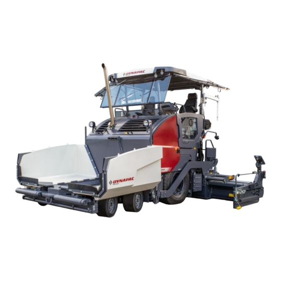
Page 29: B Vehicle Description
B Vehicle description Application The Dynapac SD2500W / SD2500WS paver finisher is a wheeled paver finisher which is used for paving bituminous mixed material, roll-down or lean-mixed concrete, track- laying ballast and unbound mineral aggregates for foundations for paving. -
Page 30: Description Of Assemblies And Functions
Description of assemblies and functions Item Designation Material compartment (hopper) Truck push rollers Tube for sensor rod (direction indicator) and holder for levelling shoe Rear wheels Levelling cylinder for paving thickness Traction roller Crossbeam pull bar Paving thickness indicator Crossbeam Travel drive Auger Screed... -
Page 31: Vehicle
Vehicle Construction The paver finisher has a welded steel frame on which the individual components are mounted. The large drive wheels together with the front tandem shaft jointly compensate the irregularities of the soil and as a result of the suspension of the screed they guarantee a particularly high paving precision. - Page 32 Engine: The paver finisher is driven by a water cooled diesel engine. For further de- tails see the technical data and the engine's instruction manual. Various engine variants in different emission classes are available as options. Stage IIIa / Tier 3 (o): There is no separate exhaust aftertreatment for this engine type when used in countries without specific regulations.
- Page 33 Steering system/operator's platform: The fully hydraulic steering system ensures easy manoeuvrability. The small turning radius permits quick and easy manoeuvring. The operating panel can be hydraulically shifted beyond the left/right outer edge of the vehicle, providing the driver with a better view of the paving area in this position. The entire operating panel can be swivelled for operation beyond the outer edge of the vehicle, and can be additionally be locked in several positions along the control platform.
- Page 34 Augers: The augers are driven and actuated independently from the conveyors. The left-hand and the right-hand half of the auger can be controlled separately. The drive system is fully hydraulic. The conveying direction can be changed towards the centre or towards the outside. This ensures that there is always a sufficient supply of material even if an excessive amount of material is required at one side.
- Page 35 Crossbeams / screed lifting device: The screed lifting device is used to lift the screed during transportation. The screed's approach angle can be changed using the eccentric adjustment facility on the crossbeam. Depending on the paving condition requirements, the crossbeam can be moved backwards or forwards.
-
Page 36: Danger Zones
Danger zones WARNING Danger for persons in the danger zone Persons in the danger zone can suffer severe or fatal inju- ries from movements and functions of the vehicle! - Remaining in the vehicle's danger zone during operation is prohibited! - During operation, only the vehicle operator and the screed personnel are allowed on the vehicle or in the danger zone. -
Page 37: Safety Devices
Safety devices 4 5 6 7... - Page 38 Item Designation Hopper transport safeguard Screed lock, mechanical / hydraulic (o) Main switch Emergency stop button Horn Ignition key Lights Protective roof latch (o) Fire extinguisher (o) Screed warning light (o) Covers, lateral flaps, coverings Foot brake Hazard warning flasher Rotary beacon (o) Located on both sides of the vehicle Safe operation is only possible when all operating and control elements are function-...
-
Page 39: Technical Data, Standard Configuration
Technical data, standard configuration Dimensions (all dimensions in mm) 2125 500 425 2240 6100 6380 2055 2550 3140 3250 For screed technical data, refer to the screed operating instructions. B 11... -
Page 40: Allowed Angle Of Rise And Slope
Allowed angle of rise and slope max. 15° max. 15° max. 15° max. 15° Before operating your vehicle in an inclined position (gradient, slope, lateral inclina- tion) which is above the specified limit value, please consult the customer service de- partment for your vehicle! Permissible approach angle max. -
Page 41: Weights Sd2500W (All Weights In T)
Weights SD2500W (all weights in t) Paver finisher without screed approx. 13.2 - 14.7 Paver finisher with screed: - V5100 approx. 16.5 - 18.0 With extension parts for max. working width, additionally max. With filled hopper approx. 13.0 additionally max. For the weights of the screed and the screed attachments, see the operating instruc- tions for the screed. -
Page 42: Performance Data Sd2500W
Performance data SD2500W V5100TV(E) 2..55 2.00 5.10 7.30 V5100TV 2.55 2.00 5.10 7.30 V6000TV(E) 3.00 2.45 6.00 7.50 V6000TV 3.00 2.45 6.00 7.50 Transport speed 0 - 20 km/h Operating speed 0 - 30 m/min Paving height -100 - 300 Max. -
Page 43: Performance Data Sd2500Ws
Performance data SD2500WS V5100TV(E) 2.55 2.00 5.10 8.80 V5100TV 2.55 2.00 5.10 8.80 V5100TH 2.55 2.00 5.10 6.60 V6000TV(E) 3.00 2.45 6.00 9.00 V6000TV 3.00 2.45 6.00 9.00 V6000TVH 3.00 2.45 6.00 7.50 Transport speed 0 - 20 km/h Operating speed 0 - 30 m/min Paving height... -
Page 44: Travel Drive/Traction Unit
Travel drive/traction unit Continuously variable hydrostatic drive, with Drive pump and engine Transmission Planetary gear Speeds (see above) Drive wheels 2 x 445/80R25 (pneumatic tyres) (water filling o) Steering wheels 4 x 560 / 390 - 300 (elastic solid rubber tyres) 2 / 4 wheel hub hydraulic motor, variable drive Front-wheel drive performance, anti-spin control... -
Page 45: Sd2500W - Engine Eu Iiib / Tier 4I (O)
5.12 SD2500W - Engine EU IIIb / Tier 4i (o) Make/type Cummins QSB 6.7-C173 Version 6-cylinder diesel engine (water-cooled) Performance 129 KW / 175PS (at 2200 rpm) Pollutant emissions in Stage IIIb / Tier 4i co-ordination with: Fuel consumption, full load 33.5 l/h Fuel consumption, 2/3 load 22.4 l/h... -
Page 46: Sd2500W - Engine Engine Eu Iv / Tier 4Final (O)
5.14 SD2500W - Engine Engine EU IV / Tier 4final (o) Make/type Cummins QSB 6.7-C173 Version 6-cylinder diesel engine (water-cooled) Performance 129 KW / 175PS (at 2200 rpm) Pollutant emissions in Stage IV / Tier 4final co-ordination with: Fuel consumption, full load 33.5 l/h Fuel consumption, 2/3 load 22.4 l/h... -
Page 47: Hydraulic System
5.16 Hydraulic system Hydraulic pumps via distribution gear Pressure generation (directly flanged to the engine) Hydraulic circuits for: - Travel drive - Auger - Conveyor Pressure distribution - Tamper / vibration - Operating functions - Fan - Clutch - Separate hydraulic circuits for options Hydraulic oil reservoir - volume (See chapter F) 5.17... -
Page 48: Screed Lifting Device
5.20 Screed lifting device At standstill: - Screed stop - Screed stop with pretensioning (max. pressure 50 bar) Special functions During paving: - Screed charging - Screed relieving (max. pressure 50 bar) Mechanical grade control Levelling system Optional systems with and without slope control 5.21 Electrical system On-board voltage... -
Page 49: Identification Points
Identification points CAUTION Danger due to missing or misunderstood vehicle signs Missing or misunderstood vehicle signs pose a danger of injuries! - Never remove any warnings or information signs from the vehicle. - Damaged or lost warning or information signs must be replaced immediately. - Page 50 B 22...
- Page 51 xxxxxxxxxxxxxxxxx B 23...
-
Page 52: Warning Signs
Warning signs Pictogram Meaning Warning - Operating instructions! Danger due to improper operation. The vehicle personnel must have read and understood the safety, operating and maintenance instructions for the ve- hicle before the vehicle is put into opera- tion! Failure to comply with the operating and warning instructions can cause se- vere or fatal injuries. - Page 53 Pictogram Meaning Warning - Danger of crushing fingers and hands due to moving, accessible vehicle parts! Crushing points can cause severe inju- ries with the loss of parts of the fingers or hand. Keep your hands at a safe distance from the danger area! Caution - Danger from incorrect tow- ing!
- Page 54 Pictogram Meaning Warning - Hazard from hydraulic reservoir and from hydraulic oil under pressure! Escaping hydraulic oil under pressure can pierce the skin and enter into the body, causing severe or fatal injuries. Always observe the operating instruc- tions! Warning - Danger from tyres filled with water! Handling tyres filled with water incorrect- ly can cause severe to fatal injuries.
-
Page 55: Information Signs
Information signs Pictogram Meaning Operating Instructions Position of the storage compartment. Lifting point Lifting the machine is only permitted at these lifting points! Lashing point Lashing the machine is only permitted at these points! Main battery switch Position of the main battery switch. Diesel fuel Position of the filling point. - Page 56 Pictogram Meaning Engine oil Position of the filling and control point. Engine coolant Position of the filling and control point. Hydraulic oil Position of the filling point. Hydraulic oil level Position of the control point. Engine oil drainage point Position of the drainage point. Gearbox oil Position of the filling and control point.
-
Page 57: Ce Marking
CE marking No. Pictogram Meaning CE, sound output level Instructive symbols, prohibitive symbols, warning symbols No. Pictogram Meaning Wear ear protectors Do not enter the area! Do not spray the area or component with water! Warning on dangers posed by batteries! First aid kit B 29... -
Page 58: Danger Symbols
Danger symbols Pictogram Meaning - XN: Danger to health! This substance can damage your health when absorbed in the body! Substance irritating to skin, eyes and respiratory system; can cause inflammation. Avoid contact with the human body; also avoid inhaling the vapours and seek medical advice if feeling unwell. -
Page 59: Further Warnings And Operating Instructions
Further warnings and operating instructions Pictogram Meaning - Warning - Hazard from unsupported screed! If the screed sags, this can cause severe or fatal injuries! Insert crossbeam lock only at crown adjustment "zero". Cross- beam lock only for transportation! Do not enter or work under screed only secured with screed lock for transportation! - Attention - danger of high voltage in... - Page 60 Pictogram Meaning Overview "Tyre pressure / working width / speed preselection" Overview "Tyre pressure / working width / speed preselection" B 32...
-
Page 61: Identification Label For The Paver Finisher (41)
Identification label for the paver finisher (41) Item Designation Paver finisher type Year of construction Operating weight, incl. all extension parts, in kg Maximum permitted total weight in kg Max. permissible load on the front axle, in kg Max. permissible load on the rear axle, in kg Maximum permissible axle load of the trailer axle in kg (o) Rated performance in kW Product identification number (PIN) -
Page 62: Explanation Of 17Pin Serial Number
Explanation of 17PIN serial number >10002014JHG002076< - Manufacturer - Family/Model - Check letter - Serial number B 34... -
Page 63: Engine Type Plate
Engine type plate The engine type plate (1) is affixed on top of the engine. The type plate states the engine type, serial number and engine data. Please state the engine number of the engine when ordering spare parts. See also operating instructions for the engine. B 35... -
Page 64: Standards
EN standards Continuous sound pressure SD2500W The operator always must use ear protection. The emission value at the ear of the driver varies depending on the materials used for paving and may even rise above 85 dB(A). If no ear protection devices are used, hearing can be impaired. The sound emission level of the paver finisher was measured under free-field condi- tions according to EN 500-6:2006 and ISO 4872. -
Page 65: Continuous Sound Pressure Sd2500Ws
Continuous sound pressure SD2500WS The operator always must use ear protection. The emission value at the ear of the driver varies depending on the materials used for paving and may even rise above 85 dB(A). If no ear protection devices are used, hearing can be impaired. The sound emission level of the paver finisher was measured under free-field condi- tions according to EN 500-6:2006 and ISO 4872. -
Page 66: Vibration Acting On The Entire Body
Vibration acting on the entire body When the vehicle is used properly, the weighted effective acceleration values at the driver’s seat of a = 0.5 m/s according to DIN EN 1032 are not exceeded. Vibrations acting on hands and arms When the vehicle is used properly, the weighted effective acceleration values at the driver’s seat of a = 2.5 m/s... -
Page 67: C13 Transportation
C 13 Transportation Safety regulations for transportation Accidents can happen when the paver finisher and the screed are not properly pre- pared for transportation or when transportation is carried out improperly! Reduce both the paver finisher and the screed to their basic widths. Remove all pro- truding parts (such as the automatic levelling system, auger limit switches, aprons, etc.). -
Page 68: Transportation On Low-Bed Trailers
Transportation on low-bed trailers Reduce the paver finisher and the screed to their basic widths; also remove any at- tached side plates. The maximum approach angle is indicated in the section entitled "Technical data"! Check the fill level of the operating substances so that these do not escape when driv- ing on an incline. - Page 69 Operation Buttons Deactivating the function lock Activate set-up mode. Close the hopper lids. Engage both hopper transport safeguards. Lift the screed. Fully extend the levelling cylinder. Retract the screed parts until the screed matches the basic width of the paver finisher. Deactivate set-up mode.
-
Page 70: Securing The Load
Securing the load The following instructions for securing the load on the low-bed trailer consist merely in examples of how to secure the load correctly. Always comply with the local regulations for securing the load and for correct use of load securing equipment. -
Page 71: Driving Onto The Low-Bed Trailer
Driving onto the low-bed trailer Make sure that there are no persons in the danger area during loading. - Use the work gear and low engine speeds to drive onto the low-bed trailer. C 13 5... -
Page 72: Lashing Equipment
Lashing equipment Use the load securing equipment, lashing straps and chains belonging to the vehicle. Additional shackles, eyebolts, edge guards and non-slip mats may be needed de- pending on the type of load securing equipment. Always comply with the stated values for permitted lashing force and load rating! Always tighten the lashing chains and straps hand-tight (100-150 daN). -
Page 73: Loading
Loading Pay attention to load distribution during loading! In some vehicles, the kingpin load is too low so that the load has to be positioned further to the back of the vehicle (A). Always heed the details regarding load distribution stipulated for the vehicle together with the centre of gravity of the paver finisher. -
Page 74: Preparing The Vehicle
Preparing the vehicle After the vehicle has been positioned on the low-loader, the following preparations must be carried out: - For movable platform: Set the retaining bolt properly (1). - Close the hopper and set the hopper transport safeguards (2) on both sides. - Position the non-slip mats under the screed across the whole width of the vehicle (3) and lower the screed. -
Page 75: Securing The Load
Securing the load Securing at the front and at the sides Step 1: fasten lashing chains at the front Diagonal lashing secures the paver finisher at the front using the lashing points on the paver finisher and on the low-load trailer. Fasten the lashing chains as shown. -
Page 76: Securing At The Rear - Screed With Side Board
Securing at the rear - screed with side board Diagonal lashing secures the paver finisher at the rear, at right angles to the direction of travel using the lashing points on the paver finisher (eyebolts) and on the low-load trailer. Fasten the lashing straps as shown. Screw the supplied eyebolts (7) first of all in the holes provided in the arms. -
Page 77: Securing At The Rear - Screed Without Side Board
Securing at the rear - screed without side board Step 1: fasten lashing straps Diagonal lashing secures the paver finisher at the rear using the lashing points on the paver finisher and on the low-load trailer. Fasten the lashing straps as shown. Step 2: fasten lashing chains Diagonal lashing secures the paver finisher at the rear using the lashing points on the paver finisher and on the low-load trailer. -
Page 78: Control Panel Transport Safeguard
Control panel transport safeguard: - Release the latch (1) to move the con- trol platform. The latch must be fixed when the control platform is set in the middle and during transport. To be able to set the lock, the platform must be positioned centrally above the vehicle frame. -
Page 79: After Transportation
After transportation - Remove the attachment devices. - Raise protective roof: See section entitled "Protective roof" - Lift the screed to the transportation position. - Start the engine and drive from the trailer at a low engine/traction speed. - Park the paver finisher in a secure spot, lower the screed and switch off the engine. - Remove the key and/or cover the operating panel with the protective hood and secure it. -
Page 80: Protective Roof (O)
Protective roof (o) NOTE Caution! Possible collision of parts The following adjustments must be made before lowering the roof: - Control platform locked in central position - Operating panel locked in central position - Operating panel fixed in lowest position and engaged in rearmost setting - Steering wheel knob is at the bottom (wheeled paver) - Driver's seats swivelled to middle setting and in... - Page 81 The protective roof can be raised and lowered with a manual hydraulic pump. The exhaust pipe is lowered or raised to- gether with the roof. - Connect the pump lever (1) to the pump (2). - Tighten bolts (3) on both sides of the roof.
-
Page 82: Transportation
Transportation Reduce the paver finisher and the screed to their basic widths; also remove any at- tached side plates. Preparations - Prepare the paver finisher for transportation (see chapter D). - Remove all overlaying or loose parts from finisher and screed (see also Screed op- erating instructions). - Page 83 Operation Buttons Deactivating the function lock Activate set-up mode. Close the hopper lids. Engage both hopper transport safeguards. Lift the screed. Fully extend the levelling cylinder. Retract the screed parts until the screed matches the basic width of the paver finisher. Extend crossbeam lock.
-
Page 84: Driving Mode
Driving mode Operation Buttons Set the fast/slow switch to "Hare" if necessary. Turn the preselector to "zero". Swivel the drive lever to maximum. The vehicle already advances slightly on deflecting the drive lever! Adjust required vehicle speed with the preselector. To stop the vehicle, swivel the drive lever to the middle setting and set the preselector to "zero". -
Page 85: Loading By Crane
Loading by crane WARNING Danger from suspended loads Crane and/or lifted vehicle can tip when lifted and cause injuries! - The vehicle may only be raised at the marked l ifting points. - Heed the operating weight of the vehicle. - Do not enter the danger zone. - Page 86 Four lifting eyes (1, 2) are provided for loading the vehicle with a crane. Depending on the type of screed which is used, the paver finisher's centre of gravity, with the screed mounted, is located in the area of the front edge (3) of the rear wheel. - Secure vehicle wherever it is parked up.
- Page 87 See section entitled "Protective roof" - Attach lifting gear to the four attachment points (1, 2). The max. permissible attachment point load at the attachment points is 73.5 kN. The permissible load applies in the vertical direction! Make sure that the paver finisher remains in a horizontal position during transportation! C 13 21...
-
Page 88: Towing
Towing Heed all regulations and apply all safety measures applicable for towing heavy con- struction machines. The towing vehicle must be capable of securing the paver finisher, even on slopes. Use only approved tow bars! If necessary, remove any attachments and accessories from the paver finisher and the screed until the basic width has been attained. - Page 89 A hand pump (1) is located under the central control platform floor panel; it must be actuated to be able to tow the machine. Pressure for releasing the traction system brakes is built up with the hand pump. - Release lock nut (2), screw threaded dowel (3) into pump as far as possible and secure with lock nut.
- Page 90 The max. permissible towing eye (9) load is: 200 kN On completion of the towing process, restore the initial status. Only release the traction system brakes when the machine is sufficiently secured against accidental rolling or is already properly connected to the towing vehicle. C 13 24...
-
Page 91: Safely Parking The Vehicle
Safely parking the vehicle When the paver finisher is parked at a lo- cation accessible to the public, it must be secured in such a way that unauthorised persons or playing children cannot dam- age the vehicle. - Pull off the ignition key and the main switch (1) and take it with you –... -
Page 92: Lifting The Vehicle With Hydraulic Lifts, Lifting Points
Lifting the vehicle with hydraulic lifts, lifting points The hydraulic lift must be rated for at least 10t. Always choose a horizontal surface with adequate load rating as installation surface for the hydraulic lift! Make sure that the hydraulic lift is securely and correctly positioned! The hydraulic lift is only intended to lift a load and not as a support. -
Page 93: D13 Operation
D 13 Operation Safety regulations Starting the engine, the travel drive, the conveyor, the auger, the screed or the lifting devices can cause injuries or even the death of persons. Make sure before starting any of these devices that no-one is working at, in or be- neath the paver finisher or within its danger area! - Do not start the engine or do not actuate any controls when this is expressly forbidden! Unless otherwise specified, the controls may only be actuated when the engine... - Page 94 DANGER Danger due to improper operation Improper operation of the vehicles can cause severe to fatal injuries! - The vehicle may only be used in the proper manner for its intended purpose. - The vehicle may only be operated by trained staff. - The vehicle operators must have made themselves famil- iar with the contents of the operating instructions.
-
Page 95: Controls
Controls Operating panel All detent switch functions which may pose a risk on starting the diesel engine (auger and conveyor conveying function) are set to the STOP function in the case of EMERGENCY STOP or restarting the control system. If settings are changed when the diesel engine is stopped ("AUTO"... - Page 96 D 13 4...
- Page 97 Pos. Designation Brief description Direction of travel Use when changing direction of travel on roads. indicator ("flasher") Four switch positions can be selected: - 0: Light OFF - 1: Parking lights ON (+operating panel lighting) Illumination switch - 2: Low-beam headlights ON (+operating panel lighting) - 3: High-beam headlights ON (+operating panel lighting) Avoid dazzling the oncoming traffic! Always have the warning lights on when moving the ma-...
- Page 98 D 13 6...
- Page 99 Pos. Designation Brief description For switching on the paver finisher functions and for continu- ously regulating the road speed – forward or reverse. Centre position: Engine in neutral; no travel drive; - To swivel the drive lever out, release by pulling the handle up. Depending on the position of the drive lever, the following functions can be activated: 1st position:...
- Page 100 D 13 8...
- Page 101 Pos. Designation Brief description For setting the maximum speed that can be reached when the drive lever is at its stop. The scale roughly matches the speed in m/min (during paving). Travel drive The vehicle must not travel at max. transport speed preselector when the hopper is full! The vehicle speed cannot be reduced to "0"...
- Page 102 D 13 10...
- Page 103 Pos. Designation Brief description Button with detent switch function and LED feedback: Front - For switching on the front working lights working lights - Switch OFF by pressing the button again ON / OFF (o) Avoid dazzling other road users! Button with detent switch function and LED feedback: Rear - For switching on the rear working lights...
- Page 104 D 13 12...
- Page 105 Pos. Designation Brief description Detent switch function and LED feedback: Windscreen wip- - For switching on the windscreen wipers ers ON / OFF (o) - Switch OFF by pressing the button again Detent switch function and LED feedback: Windscreen wash- - For engaging the windscreen washer system + wind- er system + wind- screen wipers...
- Page 106 D 13 14...
- Page 107 Pos. Designation Brief description Button with detent switch function and LED feedback: Filling pump - For switching on the filling pump Fuel tank ON / OFF (o) - Switch OFF by pressing the button again Button with detent switch function and LED feedback: Seat heating - For switching on the seat heating ON / OFF (o)
- Page 108 D 13 16...
- Page 109 Pos. Designation Brief description Buttons with detent switch function and LED feedback: - for activating the parking brake when the vehicle is stationary. Parking brake The parking brake must be deactivated to start the drive the vehicle away again. D 13 17...
- Page 110 D 13 18...
- Page 111 Pos. Designation Brief description Buttons with detent switch function and LED feedback. (LED ON = ready) - The speed control is activated by pressing the foot brake. The speed obtained after slowing down is held auto- matically. Tempomat (cruise control) - Pressing the button again switches the function off (LED ON) and the machine is accelerated to the speed set by the drive lever and the preselection po-...
- Page 112 D 13 20...
- Page 113 Pos. Designation Brief description Pushbutton function: - To close the left half of the hopper Separate actuation (o): Is required when paving in spaces where there is only Close hopper left limited space at one side or when obstacles obstruct truck unloading.
- Page 114 D 13 22...
- Page 115 The Truck Assist system is used for communication between the driver of the paver and the driver of the material truck. The corresponding signal system shows the truck driver which action to perform (reversing / stop / tip material / depart). Caution! Possible material damage through insuffi- NOTE cient instruction...
- Page 116 D 13 24...
- Page 117 Pos. Designation Brief description LED display Pushbutton function with LED feedback: - To change over to the "Start Tipping" signal. (YELLOW SIGNAL, running light ascending) - Press button again to change signal over to "Pause". Tell truck "Start (YELLOW SIGNAL, flashing). Tipping"(raise truck hopper) The button LED + button LED (41) flash-...
- Page 118 D 13 26...
- Page 119 Pos. Designation Brief description LED display Pushbutton function with LED feedback: - The "Truck Assist" function runs automatically. - Switch OFF by pressing the button again - Press button (38) to request a truck with material / Release for truck to approach (GREEN SIGNAL) The truck is detected by a laser sensor at...
- Page 120 D 13 28...
- Page 121 Pos. Designation Brief description Pushbutton function: - To extend the left half of the screed This function is not used in vehicle configurations with a Extend screed which cannot be extended. left screed On actuation, heed danger zones of moving parts of the vehicle! Pushbutton function: - To extend the right half of the screed...
- Page 122 D 13 30...
- Page 123 Pos. Designation Brief description Button with detent switch function and LED feedback: - The conveying function of the left conveyor is switched on when the drive lever is swivelled out and is continuously controlled via the material limit switch- es in the material tunnel. - Switch OFF by pressing the button again Left conveyor The function is shut off by pressing the EMERGENCY...
- Page 124 D 13 32...
- Page 125 Pos. Designation Brief description Button with detent switch function and LED feedback: - The function of the left conveyor is permanently switched on at full conveying rate and is activated/de- activated with the material limit switch in the material tunnel. - Switch OFF by pressing the button again.
- Page 126 D 13 34...
- Page 127 Pos. Designation Brief description Pushbutton function: - The conveying direction of the conveyor can be re- versed in order to slightly reverse paving material for example which may be present in the material tunnel. The function can be triggered in all modes of the conveyor.
- Page 128 D 13 36...
- Page 129 Pos. Designation Brief description Button with detent switch function and LED feedback: - The conveying function of the left half of the auger is switched on when the drive lever is swivelled out and is continuously controlled via the material limit switches. - Switch OFF by pressing the button again Left auger The function is shut off by pressing the EMERGENCY...
- Page 130 D 13 38...
- Page 131 Pos. Designation Brief description Button with detent switch function and LED feedback: - The conveying function of the left half of the auger is switched on continuously with full delivery capacity, without material control via the limit switches. - Switch OFF by pressing the button again Left auger The function is shut off by pressing the EMERGENCY "MANUAL"...
- Page 132 D 13 40...
- Page 133 Pos. Designation Brief description Pushbutton function: - To manually trigger the conveying function for the left Left auger half of the auger, conveying direction inwards. "MANUAL" For manual triggering, the auger function must be conveying switched to "AUTO" or "MANUAL" direction inwards On manual triggering, the automatic function is overrid-...
- Page 134 D 13 42...
- Page 135 Pos. Designation Brief description Detent switch function and LED feedback: - In transport gear: To lock all functions relevant to paving. Despite "Auto" settings in the individual functions, these are not activated when the drive lever is swivelled out. LED permanently ON - In working gear: To lock all detent functions relevant to paving.
- Page 136 D 13 44...
- Page 137 Pos. Designation Brief description Button with detent switch function and LED feedback: - For manual actuation of the levelling cylinders when the automatic levelling system is switched off. - Switch OFF by pressing the button again The corresponding switch on the remote control must Adjustment be switched to "Manual"...
- Page 138 D 13 46...
- Page 139 Pos. Designation Brief description Pushbutton function: - To adjust the selected function in the corresponding Adjustment button: direction. Retract / lift on left On actuation, heed danger zones of moving parts of the vehicle! Pushbutton function: - To adjust the selected function in the corresponding Adjustment button: direction.
- Page 140 D 13 48...
- Page 141 Pos. Designation Brief description Detent switch function and LED feedback: Filling function for the paving process. The diesel engine's speed is increased to the preselected nominal speed and all conveying functions set to "Auto- matic" (conveyor and auger) are engaged. The main function switch must be set to the OFF position.
- Page 142 D 13 50...
- Page 143 Pos. Designation Brief description Pushbutton function with LED feedback: - For lifting the screed (LED ON) and for switching off the "Screed floating position" function Lift screed Check whether the screed transport safeguard is inserted! On actuation, heed danger zones of moving parts of the vehicle! Button with detent switch function and LED feedback The main function switch must be set to the OFF position.
- Page 144 D 13 52...
- Page 145 Pos. Designation Brief description Button with detent switch function and LED feedback: - Tamper ON and OFF function. - Activation is carried out by swivelling the drive lever out. - Switch OFF by pressing the button again. Tamper (screed-specific) The main function switch must be set to the OFF position.
- Page 146 D 13 54...
- Page 147 Pos. Designation Brief description Button with detent switch function and LED feedback: - For relieving the screed to influence the traction force and compaction ratio. Screed relieving - Switch OFF by pressing the button again or switching between screed relieving and screed charging. To preset the hydraulic oil pressure, switch this button and the "Set-up mode"...
- Page 148 D 13 56...
- Page 149 Pos. Designation Brief description Pushbutton function with LED feedback: - To hydraulically extend the crossbeam lock. Extend cross- Before retracting and extending the lock, raise the beam lock (o) crossbeams slightly over the locking bolts (raise the screed)! Pushbutton function with LED feedback: - To hydraulically retract the screed lock.
- Page 150 D 13 58...
- Page 151 The "Set Assist" function prepares the paver to relocate to another section of road- works or for transportation. When the function is activated, previously selected vehicle functions are carried out to make the vehicle ready for transport. The function can be reset after relocating the paver. This restores the corresponding elements to the previously saved working condi- tion /position.
-
Page 152: Remote Control
Remote control D 13 60... - Page 153 Depending on the side of the vehicle, the button blocks (A) and (B) are assigned to either the auger or the conveyor control system. The relevant element which is con- trolled is indicated by an illuminated symbol (C). Important! Do not disconnect remote controls during operation! This causes the paver finisher to be shut down! D 13 61...
- Page 154 D 13 62...
- Page 155 Pos. Designation Brief description Press in an emergency (danger to persons, impending colli- sion, etc.)! Pressing the emergency stop button switches off the en- gine, the drives and the steering system. Making way, lifting the screed or other actions are then no Emergency stop longer possible! Danger of accident! button...
- Page 156 D 13 64...
- Page 157 Pos. Designation Brief description Button with detent switch function and LED feedback: - The conveying function of the corresponding half of the auger is switched on continuously with full deliv- ery capacity, without material control via the limit switches. Auger - Switch OFF by pressing the button again "MANUAL"...
- Page 158 D 13 66...
- Page 159 Pos. Designation Brief description Pushbutton function: - Plus/minus buttons for adjusting the delivery capacity. - The delivery capacity is slowed down or speeded up Auger delivery depending on the length of time for which the button capacity is pressed. The auger function must be switched to "AUTO" or "MANUAL"...
- Page 160 D 13 68...
- Page 161 Pos. Designation Brief description Button with detent switch function and LED feedback: - The conveying function of the corresponding half of the conveyor is switched on continuously with full de- livery capacity, without material control via the limit switches. Conveyor - Switch OFF by pressing the button again "MANUAL"...
- Page 162 D 13 70...
- Page 163 Pos. Designation Brief description Pushbutton function: - Plus/minus buttons for adjusting the delivery capacity. - The delivery capacity is slowed down or speeded up Delivery capacity depending on the length of time for which the button Conveyor is pressed. The conveyor function must be switched to "AUTO" or "MANUAL"...
- Page 164 D 13 72...
- Page 165 Pos. Designation Brief description Button with detent switch function and LED feedback: Operating mode - Operating mode "AUTO" (LED ON): Levelling levelling engages automatically when the drive lever "AUTO" / is swivelled out for paving operation. "MANUAL" - Operating mode "MANUAL" (LED OFF): left levelling switched off.
- Page 166 D 13 74...
- Page 167 Pos. Designation Brief description Button with detent switch function and LED feedback: Operating mode - Operating mode "AUTO" (LED ON): Levelling levelling engages automatically when the drive lever "AUTO" / is swivelled out for paving operation. "MANUAL" - Operating mode "MANUAL" (LED OFF): right levelling switched off.
- Page 168 D 13 76...
- Page 169 Pos. Designation Brief description Pushbutton function: - For manual actuation of the levelling cylinders on the corresponding side of the vehicle when the automatic Levelling cylinder levelling system is switched off (LED OFF). manual On adjustment, note the levelling display in the remote control display! Pushbutton function: - To retract and extend the screed half on the corre-...
- Page 170 D 13 78...
-
Page 171: D22 Operating The Display
D 22 Operating the display D 22 1... -
Page 172: Operation Of The Input And Display Terminal
Operation of the input and display terminal Button layout on the display - (A) Jog dial (knob to be turned+push button): - Turn: - to select various adjustment parameters within a menu - to adjust the parameter - to select various selection possibilities within a menu - Press: - to release the adjustment of a parameter - to confirm a parameter adjustment... - Page 173 To confirm an active/opened menu, the colour of the cor- responding symbol changes from pale to dark grey! - (F) Display area for status, warning and error messages: - To show current earnings or error messages. The colour of the symbol indicates whether it is a status, warning or error message. Colour code Explanation RED - error message...
-
Page 174: Menu Operation - Procedure For Adjusting Parameters
Menu operation - procedure for adjusting parameters D 22 4... - Page 175 Example: Adjusting the screed temperature - The "Home" menu is open in the display. - Press button (A) to open the "Engine Speed" menu. - The "Engine Speed" menu is open in the display. - Press button (B) to open the "Screed Heater" menu. - Turn jog dial (C) to make the cursor appear.
-
Page 176: Selecting And Changing An Adjustment Parameter In A Menu
Selecting and changing an adjustment parameter in a menu - Press jog dial (C) to activate the parameter adjustment. A blue frame appears around the top adjustment parameter in the menu. - Turn jog dial (C) in the corresponding direction until the blue frame is around the required adjustment parameter. -
Page 177: Selecting And Changing A Selection Possibility In A Menu
Selecting and changing a selection possibility in a menu - Press jog dial to activate the parameter adjustment. A blue frame appears around the top selection possibility in the menu. - Turn jog dial in the corresponding direction until the blue frame is around the re- quired selection possibility. -
Page 178: Menu Structure
Menu structure Menu of the "Home" displays Displays: - (1) Speed: - Paving (tortoise)-(m/min) / (ft/min) - Driving (hare) - (km/h) / (mph) - (2) Fuel gauge ® - (3) Level AdBlue / DEF tank (o) If the level is too low, a warning also appears. - (4) Paving material - conveyor level left / right - (5) Paving material - auger level left / right - (6) Actual temperature of the screen heater (°C) / (°F) - Page 179 - (12) Target slope - left / right (%) (o) - (13) Overall width screed (cm) / (inch) (o) The remote control must be reset to measure the overall width. - (14) Extension distance - levelling cylinder left (cm) / (inch) (o) - (15) Extension distance - levelling cylinder right(cm) / (inch) (o) - (16) Type of material control being used - (17) Truck Assist control (o)
-
Page 180: Home" Menu - Sub-Menus
"HOME" menu - sub-menus Open the following sub-menus: - (1) Show "Home" functions / "Quick Settings" - (2) Call "Engine Speed" menu / Engine measured value display + sub-menus. - (3) "Paving Parameters" menu + sub-menus. - (4) "Camera display" menu + sub-menus.(o) - (5) "Error Memory"... - Page 181 If the corresponding function button of an opened sub-menu is pressed again, the Home menu appears and the sub-menu display remains. D 22 11...
-
Page 182: Home" Functions / "Quick Settings
"Home" functions / "Quick Settings" Menu for directly activating various functions. - Press corresponding function button to show the functions / quick settings (1) to (6). Press once more to hide the functions again. Pressing the adjacent function button activates or deac- tivates the functions. - Page 183 - (4) "Joint hopper actuation" function - Both hopper halves are actuated together with one of the hopper function switch- es (open hopper / close hopper). - (5) "Automatic steering unit" function - The vehicle is steered automatically via corresponding sensing along a reference (e.g.
-
Page 184: Engine Speed" Menu / Engine Measured Value Display
"Engine Speed" menu / Engine measured value display Menu for adjusting the engine speed and for checking various measured values of the engine. - (1) Nominal speed display and adjustment parameters Adjusted directly by pressing the job dial. Adjustment is carried out in steps of 50; the engine speed is adapted directly. - (2) Actual engine speed - (3) Engine oil pressure (bar) - (4) On-board voltage (V) -
Page 185: Material Management" Measured Value Display
"Material Management" measured value display Menu for checking the following parameters: - (1) Paving material level (%) conveyor left - (2) Paving material level (%) conveyor right - (3) Paving material level (%) auger left - (4) Paving material level (%) auger right - (5) Tamper speed (n/min) - (6) Vibrations speed (n/min) D 22 15... -
Page 186: Screed Heater" Adjustment And Display Menu (O)
"Screed Heater" adjustment and display menu (o) Menu for adjusting the nominal screed heater temperature and for checking the actu- al temperatures. - (1) Nominal screed heater temperature display and adjustment parameters. Press encoder (A) to start the editing menu. Setting range 50-180°C - (2) Average actual temperature of all screed sections (°C) / (°F) - (3) Actual temperature basic screed left (°C) / (°F) -
Page 187: Paving Area / Automatic Steering Unit" Menu
"Paving Area / Automatic Steering Unit" menu Menu for retrieving and resetting the current paving area, for showing the steering monitoring and resetting the steering monitoring reference. - (1) Current paving distance (m) - Reset / set value to zero: Select function (1.1) with the job dial and press to reset. As confirmation, the display changes for 5 to 10 seconds during reset. -
Page 188: Front Wheel Drive" Measured Value Display (O)
"Front wheel drive" measured value display (o) Display of the power provided for the front wheel drive. - (1) Power display left front wheel drive. - (2) Power display right front wheel drive. D 22 18... -
Page 189: Particulate Filter Regeneration" Menu (O)
"Particulate filter regeneration" menu (o) 1b 2a Menu for triggering requested active filter regeneration and for disabling automatic fil- ter regeneration. - (1) Particulate filter regeneration, manual: - for triggering necessary particulate filter regeneration. Necessary regeneration is indicated by the regeneration warning sign (1a)! Please heed the notes in the "Terminal error messages"... - Page 190 Danger from particulate filter regeneration DANGER Improper particulate filter regeneration can cause severe to fatal injuries! - Keep the outlet of the exhaust pipe out of the reach of peo- ple and of objects that can burn, melt or explode! - There may not be any people or objects within a radius of 0.6 m of the exhaust outlet! - There may not be any objects or substances that can burn,...
-
Page 191: Paving Parameters" Menu
"Paving parameters" menu Menu for showing and adjusting the paving parameters. - (1) Current course thickness parameter - The following course thickness parameters can be selected: - (1a) Surface course >, low paving speed - (1b) Surface course >>, high paving speed - (1c) Binder course >, low paving speed - (1d) Binder course >>, high paving speed - (1e) Foundation... - Page 192 - (2) Left conveyor speed (%) display and adjustment parameters - (3) Right conveyor speed (%) display and adjustment parameters - (4) Left auger speed (%) display and adjustment parameters - (5) Right auger speed (%) display and adjustment parameters - (6) Nominal tamper speed (n/min) display and adjustment parameters - (7) Nominal vibration speed (n/min) display and adjustment parameters Tamper and vibration range depending on screed type.
-
Page 193: Adjusting The Paving Parameters
Adjusting the paving parameters Functions: - (8) "Save Parameter" function As confirmation, the display changes for 5 to 10 seconds during saving. - (9): "Load Parameter" function As confirmation, the display changes for 5 to 10 seconds during loading. - (10): "Parameter Reset - Load Factory Settings" function Firstly the system requests reset confirmation. - Page 194 Overview "Course Thickness Parameters" Menu for viewing the speeds saved for all conveying and compacting elements ac- cording to the course thickness parameters. Back to the main menu: - (1) "Paving Parameters" menu. D 22 24...
-
Page 195: Camera Display" Menu (O)
"Camera display" menu (o) Machine parts partly concealed from view can be displayed by the camera system. When this function is called up, display camera 1 appears. - (1) Show camera 1 display. - (2) Show camera 2 display. D 22 25... -
Page 196: Error Memory" Menu
"Error Memory" menu Menu for retrieving existing error messages. - (1) Number of error messages with travel drive stop. - Open detailed display "Error Messages With Travel Drive Stop": (1.1). - (2) Number of vehicle warning messages. - Open detailed display "Vehicle Warning Messages": (2.1). - (3) Number of engine error messages. -
Page 197: Detailed Display "Error Messages With Travel Drive Stop
Detailed display "Error Messages With Travel Drive Stop" Display of existing error messages in a table. - (1) Error code. - (2) Error description. - (3) Designation of the faulty part as per BMK/EIC list. Press the job dial to scroll through the list. D 22 27... -
Page 198: Detailed Display "Vehicle Warning Messages
Detailed display "Vehicle Warning Messages" Display of existing error messages in a table. - (1) Error code. - (2) Error description. - (3) Designation of the faulty part as per BMK/EIC list. Press the job dial to scroll through the list. - Delete list of error messages: (4). -
Page 199: Detailed Display "Engine Error Messages
Detailed display "Engine Error Messages" Display of existing error messages in a table. - (1) SPN code. - (2) FMI code. - (3) OC error frequency. All error messages can be identified in the section "Error codes drive engine". Press the job dial to scroll through the list. D 22 29... -
Page 200: Basic" Menu
"Basic" menu The "Basic" menu can be opened from every menu, sub-menu or display. Menu for opening the following sub-menus: - (1) "Home" menu - Display and quick settings menu. - (2) "Service" menu - Menu for service technician (password required) - (3) "Info &... - Page 201 "Service" menu Password-protected menu for various service settings. D 22 31...
-
Page 202: Info & Settings" Menu
"Info & Settings" menu Menu for calling up various vehicle information and sub-menus for various settings. Display of the following information: - (1) Software version of the vehicle - (2) Software version of the display - (3) Engine operating hours (h) - (4) Next service interval (h) If consultation with Technical Support is required for your vehicle, always specify the software version! -
Page 203: Screed" Set-Up Menu
"Screed" set-up menu Menu for setting up the basic screed settings and screed functions. - (1) Display and adjustment parame- ters for the screed type - Screed type 1, 2, 3, 4, 5 Please consult the screed type plate for the parameter to be entered here, corre- sponding to the last number of the screed type. - Page 204 - (4) Display and adjustment parameters for the central lubrication system - (4.1): Shortened lubrication interval - (4.2): Standard lubrication interval - (4.3): Extended lubrication interval If necessary, the lubrication interval has to be adjusted to the prevailing paving situ- ation and to the material.
-
Page 205: Paving / Travel" Set-Up Menu
"Paving / Travel" set-up menu Menu for setting up the vehicle and levelling functions. - (1) Display and adjustment parameters for "Delayed Front Hopper" - delay time (sec). (o) After closing the hopper lids, the front hopper is only raised after the adjusted time has expired. - Page 206 - (3) Selection "Cross Levelling" - (0): Cross levelling OFF - (1): Only data display of the opposite side of the vehicle. - (2): Data display and control of the opposite side of the vehicle. - (3): Split screen on the remote controls: simultaneous data display and operation of both sides of the vehicle possible.
-
Page 207: Truck Assist / Set Assist" Set-Up Menu
"Truck Assist / Set Assist" set-up menu Menu for setting up the "Truck Assist" and "Set Assist" functions. - (1) Selection "Truck Distance" In order to adjust to the prevailing situation, the truck’s automatic detection function can be preset to 3 different distances (paver/truck). - (1.1): (1.1): Shortened distance - (1.2): (1.2): Medium distance - (1.3): (1.3): Extended distance... -
Page 208: Day/Night Lighting" Set-Up Menu
"Day/Night Lighting" set-up menu Menu for adjusting the illuminance of various control elements. - (2) Monitor brightness display and adjustment parameters - (2.1): daytime light (%) - (2.2): nighttime light (%) - (3) Truck Assist display and adjustment parameters - (3.1): daytime light (%) - (3.2): nighttime light (%) D 22 38... -
Page 209: Display" Set-Up Menu
"Display" set-up menu Menu for setting up basic display settings. - (1) Selection "System Language" - English / German - (2) Selection "Units of measurement" - Metric / Imperial (US) - (3) "Time" display and adjustment parameters - h/h : min/min - 24h / PM/AM - (4) "Date"... - Page 210 "Camera / display" set-up menu Menu for setting up the camera display. - (1) Brightness display and adjustment parameters - (2) Contrast display and adjustment parameters - (3) Colour display and adjustment parameters Setting range 0-100% Open the following sub-menus: - (4) "Display"...
- Page 211 "Licence text" display Display of the software licence text. Open the following sub-menus: - (1) "Display" set-up menu. - (2) "Camera / display" set-up D 22 41...
- Page 212 Terminal error messages Status, warning and error messages symbols Command Symbol in the display High beam headlights control The high beam headlights are switched on. Avoid dazzling the oncoming traffic! Check direction of travel indicator Flashes whenever direction of travel indicator is activated.
- Page 213 Command Symbol in the display Indicator lamp automatic particulate filter re- generation - deactivated Particulate filter regeneration is deactivated. Automatic regeneration should only be deacti- vated if the operating status of the paver finish- er does not permit any automatic function. see "Particulate filter regeneration"...
- Page 214 Command Symbol in the display Indicator lamp fuel reserve The fuel is down to the reserve level in the tank. Approx. 10% remains Urgent need to refuel! Pre-heating indicator (yellow) Pre-heating is started with the ignition starter by switching the ignition on. (ignition key in position 1).
- Page 215 Command Symbol in the display Pending service: A maintenance interval is about to expire. Proceed immediately with maintenance to avoid subsequent damage! Service overdue: A maintenance interval is overdue. Proceed immediately with maintenance to avoid subsequent damage! D 22 45...
- Page 216 Command Symbol in the display - Error message "Engine Malfunction" There is a malfunction in the engine. Switch off the drive engine immediately! Error details can be viewed in the "Error Memory" display menu. Lights up for a few seconds once the ignition has been switched on for checking purposes.
- Page 217 Command Symbol in the display Engine stop: Display for all error messages with machine stop. Hydraulic filter. The hydraulic filter must be replaced. Replace filter element acc. to Maintenance Instructions! Engine oil pressure The oil pressure is insufficient. Switch off the engine immediately! For further possible faults, see Engine's op- erating instructions.
- Page 218 Drive engine error codes If a fault is detected on the engine, this is shown by the corresponding indication (1) in the display. D 22 48...
- Page 219 The error message that can be viewed in the corresponding menu contains several numerical codes, which clearly define the fault after decoding. Press the job dial to scroll through the list. It may be possible to continue operating the vehicle, depending on the severity of the error.
- Page 220 Example: D 22 50...
- Page 221 Explanation: Warning light and display signal a serious fault on the drive engine with automatic or necessary engine shut-down. Display: SPN: FMI: Cause: Cable break on sensor for rail pressure. Effect: Engine shut-down. Frequency: Fault occurs for the 1st time. Notify customer service of the error number displayed on your paver finisher;...
- Page 222 Error codes Diesel Engine Failure-Codes chart Fault Lamp Cumins Description Code Description Engine Control Module Critical Controller #1 Internal Failure - Bad intelligent device or component Engine Magnetic System Speed/Position Diagnostic Code Lost Both of Two Signals - Data erratic, intermittent or incorrect Engine Intake Intake Manifold 1 Pressure Sensor Circuit - Voltage above normal, or Amber...
- Page 223 Diesel Engine Failure-Codes chart Fault Lamp Cumins Description Code Description Accelerator Pedal or Lever Position Accelerator Pedal Sensor 1 - Data valid but above normal operational range - Most Position 1 Severe Level Engine Coolant Temperature - Data Engine Coolant Temperature valid but above normal operational range - Most Severe Level Engine Intake...
- Page 224 Diesel Engine Failure-Codes chart Fault Lamp Cumins Description Code Description Coolant Pressure Sensor Circuit - Engine Coolant Amber Pressure Voltage below normal, or shorted to low source Coolant Pressure - Data Valid But Engine Coolant Amber Pressure Below Normal Operating Range - Moderately Severe Level Engine Crankshaft Speed/Position - Engine Speed Data valid but above normal operational range - Most Severe Level...
- Page 225 Diesel Engine Failure-Codes chart Fault Lamp Cumins Description Code Description Engine Fuel Engine Fuel Pump Pressurizing Assembly 1 Circuit - Voltage above 1347 Amber Pump Pressurizing normal, or shorted to high source Assembly #2 Engine Fuel Engine Fuel Pump Pressurizing Assembly 1 - Mechanical system not 1347 Amber Pump Pressurizing...
- Page 226 Diesel Engine Failure-Codes chart Fault Lamp Cumins Description Code Description Injector Solenoid Driver Cylinder 2 Engine Injector Amber Cylinder #02 Circuit - Current below normal or open circuit Injector Solenoid Driver Cylinder 4 Engine Injector Amber Cylinder #04 Circuit - Current below normal or open circuit Engine Coolant Engine Coolant Temperature - Data erratic, intermittent or incorrect Amber...
- Page 227 Diesel Engine Failure-Codes chart Fault Lamp Cumins Description Code Description J1939 Network #1, Primary SAE J1939 Datalink - Abnormal update rate None Vehicle Network (previously SAE J1939 Data Link) Water in Fuel Indicator Sensor Water In Fuel Amber Indicator Circuit - Voltage above normal, or shorted to high source Water in Fuel Indicator Sensor Water In Fuel Amber...
- Page 228 Diesel Engine Failure-Codes chart Fault Lamp Cumins Description Code Description Engine Multiple Unit Synchronization Switch 1377 Amber Synchronization - Data erratic, intermittent or incorrect Switch Sensor Supply 6 Circuit - Voltage Sensor supply volt- 3514 Amber age 6 above normal, or shorted to high source Sensor Supply 6 Circuit - Voltage Sensor supply volt- 3514...
- Page 229 Diesel Engine Failure-Codes chart Fault Lamp Cumins Description Code Description Engine External Auxiliary Commanded Dual Output Shutdown - Special Instructions Protection Input Engine was Shut Engine Shut Down Hot - Condition Exists 1383 None Down Hot Engine Turbocharger 1 Compressor Intake Turbocharger 1 Pressure - Data Valid But Below 1176...
- Page 230 Diesel Engine Failure-Codes chart Fault Lamp Cumins Description Code Description Engine Turbocharger 1 Compressor Intake Pressure Circuit - Voltage below Turbocharger 1 1176 Amber Compressor normal, or shorted to low source Intake Pressure Engine Turbocharger 1 Compressor Intake Pressure - Data erratic, intermit- Turbocharger 1 1176 Amber...
- Page 231 Diesel Engine Failure-Codes chart Fault Lamp Cumins Description Code Description Control Module Identification Input Incompatible 1257 1563 Monitor/Controller State Error - Data erratic, intermittent or incorrect Generator Output Frequency Adjust Potentiometer Circuit - Voltage above normal, or shorted to high 1411 4182 Amber...
- Page 232 Diesel Engine Failure-Codes chart Fault Lamp Cumins Description Code Description Injector Solenoid Driver Cylinder 15 Engine Injector 1556 Amber Cylinder #15 Circuit - Current below normal or open circuit Injector Solenoid Driver Cylinder 16 Engine Injector 1557 Amber Cylinder #16 Circuit - Current below normal or open circuit Auxiliary Pressure Sensor Input 1 Auxiliary...
- Page 233 Diesel Engine Failure-Codes chart Fault Lamp Cumins Description Code Description Aftertreatment 1 Aftertreatment 1 Diesel Exhaust Fluid Tank Heater - Voltage above Diesel Exhaust 1683 3363 Amber Fluid Tank 1 normal, or shorted to high source Heater Aftertreatment 1 Aftertreatment 1 Diesel Exhaust Fluid Tank Heater - Voltage below Diesel Exhaust 1684 3363...
- Page 234 Diesel Engine Failure-Codes chart Fault Lamp Cumins Description Code Description Engine Crankcase Pressure Circuit - 1843 Amber Crankcase Voltage above normal, or shorted to high source Pressure Engine Crankcase Pressure Circuit - 1844 Amber Crankcase Voltage below normal, or shorted to low source Pressure Engine Coolant Engine Coolant Temperature - Special Instructions...
- Page 235 Diesel Engine Failure-Codes chart Fault Lamp Cumins Description Code Description Aftertreatment 1 Aftertreatment Diesel Particulate Diesel Particulate Filter Differential Pressure - Data valid but above normal Operating 1922 3251 Filter Differential Range Pressure Aftertreatment 1 Aftertreatment Fuel Shutoff Valve 1923 3482 Amber Fuel Enable...
- Page 236 Diesel Engine Failure-Codes chart Fault Lamp Cumins Description Code Description Amber Engine Crankcase Pressure - Data Valid 1974 (Blink- Crankcase But Above Normal Operating Range - Least Severe Level ing) Pressure Aftertreatment Aftertreatment Doser Circuit - 1977 3556 Amber Hydrocarbon Current below normal or open circuit.
- Page 237 Diesel Engine Failure-Codes chart Fault Lamp Cumins Description Code Description Battery Temperature - Data Valid Battery 1 2264 1800 Amber Temperature But Below Normal Operating Range - Moderately Severe Level Engine Electric Electric Lift Pump for Engine Fuel Supply Circuit - Voltage above nor- 2265 1075 Amber...
- Page 238 Diesel Engine Failure-Codes chart Fault Lamp Cumins Description Code Description Engine Exhaust Gas Recirculation EGR Valve Control Circuit - Current above normal or grounded circuit 2353 2791 Amber 1 (EGR1) Valve Control Engine Exhaust EGR Valve Control Circuit - Mechanical system not responding or out Gas Recirculation 2357 2791...
- Page 239 Diesel Engine Failure-Codes chart Fault Lamp Cumins Description Code Description Engine Turbocharger 1 Turbocharger Turbine Intake Temperature - Data Valid But Above 2451 2789 None Calculated Normal Operating Range - Moderately S Turbine Intake Temperature Engine Crankshaft Speed/Position - Data Valid But Above Normal 2468 Amber Engine Speed...
- Page 240 Diesel Engine Failure-Codes chart Fault Lamp Cumins Description Code Description At Least One Unacknowledged 2662 Amber Controller #1 Moderately Severe Fault - Condition Exists Aftertreatment Outlet Oxygen Aftertreatment 1 2683 3227 Amber Outlet O2 Sensor Circuit - Abnormal update rate Crankcase Depression Valve - Crankcase 2699...
- Page 241 Diesel Engine Failure-Codes chart Fault Lamp Cumins Description Code Description Diesel Particulate Particulate Trap Active Amber Filter Active Regeneration Inhibited Due to Inhibit 2777 3703 (Blink- Regeneration Inhib- ing) ited Due to Inhibit Switch - Condition Exists Switch Aftertreatment Fuel Rate - Data Aftertreatment 1 2778 3481...
- Page 242 Diesel Engine Failure-Codes chart Fault Lamp Cumins Description Code Description Engine Exhaust Gas Recirculation Outlet Pressure Sensor Circuit - Engine Exhaust Voltage below normal, or shorted to 3137 5019 Amber Gas Recirculation 1 Outlet Pressure low source Engine Exhaust Engine Exhaust Gas Recirculation 3138 5019 Amber...
- Page 243 Diesel Engine Failure-Codes chart Fault Lamp Cumins Description Code Description Aftertreatment Warm Up Diesel Aftertreatment Warm Up Diesel Oxidation Catalyst Outlet Tempera- 3156 4810 Amber Oxidation ture Sensor Circuit - Voltage below normal Catalyst Outlet Temperature Aftertreatment Aftertreatment Warm Up Diesel Oxidation Catalyst Outlet Tempera- Warm Up Diesel 3157 4810...
- Page 244 Diesel Engine Failure-Codes chart Fault Lamp Cumins Description Code Description Aftertreatment 1 Intake NOx Sensor Aftertreatment 1 3228 3216 Amber Intake NOx - Data erratic, intermittent or incorrect Aftertreatment 1 Aftertreatment 1 SCR Intake SCR Catalyst Temperature - Data valid but above normal operational range - Most 3229 4360 Intake Gas...
- Page 245 Diesel Engine Failure-Codes chart Fault Lamp Cumins Description Code Description Aftertreatment 1 Aftertreatment 1 Diesel Particulate Diesel Particulate Filter Intake Temperature - Data Valid But Above Normal Operating 3253 3242 Filter Intake Gas Range Temperature Aftertreatment 1 Aftertreatment 1 Diesel Particulate Diesel Particulate Filter Intake Temperature - Data Valid But Above Normal Operating 3254...
- Page 246 Diesel Engine Failure-Codes chart Fault Lamp Cumins Description Code Description Aftertreatment 1 Aftertreatment 1 Diesel Particulate Filter Intake Temperature - Data Diesel Particulate 3318 3242 Amber Filter Intake Gas erratic, intermittent or incorrect Temperature Aftertreatment 1 Aftertreatment 1 Diesel Particulate Diesel Particulate Filter Outlet Temperature Sensor 3319...
- Page 247 Diesel Engine Failure-Codes chart Fault Lamp Cumins Description Code Description Engine Turbocharger 1 Turbocharger 1 Compressor Intake Temperature Sensor - Abnormal 3369 1172 Amber Compressor update rate Intake Temperature Engine Turbocharger 1 Compressor Intake Temperature Sensor - Received Turbocharger 1 3371 1172 Amber...
- Page 248 Diesel Engine Failure-Codes chart Fault Lamp Cumins Description Code Description Aftertreatment 1 Aftertreatment Diesel Exhaust Fluid Line Heater 3 Circuit - Voltage Diesel Exhaust 3423 4344 Amber Fluid Line Heater below normal, or shorted to low source 3 State Aftertreatment 1 Aftertreatment Diesel Exhaust Fluid Line Heater 3 Circuit - Current Diesel Exhaust 3425...
- Page 249 Diesel Engine Failure-Codes chart Fault Lamp Cumins Description Code Description NOx limits exceeded due to Aftertreatment Diesel Exhaust Fluid 3547 4096 None Empty Diesel Tank Empty - Condition Exists Exhaust Fluid Tank Engine Wait to Start Lamp - Engine Wait to 3555 1081 Amber...
- Page 250 Diesel Engine Failure-Codes chart Fault Lamp Cumins Description Code Description Aftertreatment SCR Catalyst Aftertreatment 1 Conversion Efficiency - Data Valid 3582 4364 Amber SCR Conversion But Below Normal Operating Range Efficiency - Moderately Severe Level Aftertreatment 1 Aftertreatment 1 Outlet NOx Sensor 3583 5031 Amber...
- Page 251 Diesel Engine Failure-Codes chart Fault Lamp Cumins Description Code Description Engine Protection Torque Derate - Engine Protection 3714 1569 Amber Torque Derate Condition Exists Engine Speed At Engine Speed At Idle - Data Valid Idle, Point 1 But Above Normal Operating Range 3715 Amber (Engine...
- Page 252 Diesel Engine Failure-Codes chart Fault Lamp Cumins Description Code Description Aftertreatment Diesel Exhaust Fluid 3755 5394 None Dosing Valve - Data erratic, intermittent or incorrect Auxiliary Temperature Sensor Input Auxiliary 3765 Amber Temperature 2 2 Circuit - Voltage above normal, or shorted to high source Auxiliary Temperature Sensor Input Auxiliary 3766...
- Page 253 Diesel Engine Failure-Codes chart Fault Lamp Cumins Description Code Description Aftertreatment 1 Aftertreatment 1 SCR Intermediate 3911 5848 Amber SCR Intermediate NH3 Sensor - Abnormal update rate Aftertreatment 1 SCR Intermediate Aftertreatment 1 Outlet NH3 Gas Sensor Heater - Abnormal rate of 3912 5853 Amber...
- Page 254 Diesel Engine Failure-Codes chart Fault Lamp Cumins Description Code Description Aftertreatment Selective Catalytic Reduction Temperature Sensor 4152 5743 Amber Module - Abnormal update rate Aftertreatment 1 Outlet Soot Sensor Heater - Voltage Above Normal, or 4153 5747 Amber Shorted to High Source Aftertreatment 1 Outlet Soot Sensor 4154 5747...
- Page 255 Diesel Engine Failure-Codes chart Fault Lamp Cumins Description Code Description Aftertreatment 1 Diesel Exhaust Fluid Dosing Unit Heater - Voltage 4168 5745 Amber Above Normal, or Shorted to High Aftertreatment 1 Diesel Exhaust Fluid Dosing Unit Heater - Voltage below normal, or shorted to low 4169 5745 Amber...
- Page 256 Diesel Engine Failure-Codes chart Fault Lamp Cumins Description Code Description Aftertreatment 1 Diesel Exhaust Fluid Dosing Unit Heater 4251 5798 Amber Temperature - Abnormal Rate of Change Engine Wait to Start Lamp - Engine Wait to 4252 1081 Amber Start Lamp Condition Exists Aftertreatment Warm Up Diesel Oxidation Catalyst Temperature...
- Page 257 Diesel Engine Failure-Codes chart Fault Lamp Cumins Description Code Description Aftertreatment 1 Aftertreatment 1 SCR Intermediate 4281 5848 Amber SCR Intermediate NH3 - Data erratic, intermittent or incorrect Desired Engine Fueling State - 4284 5793 Amber Abnormal Update Rate Closed Crankcase Ventilation System Pressure Sensor - Voltage 4286 520595...
- Page 258 Diesel Engine Failure-Codes chart Fault Lamp Cumins Description Code Description SCR Monitoring System Malfunction 4489 5842 Amber - Condition Exists Vehicle Vehicle Identification Number - Out of Calibration 4517 Amber Identification Number Brake Pedal Position - Data erratic, Brake Pedal 4526 Amber Position...
- Page 259 Diesel Engine Failure-Codes chart Fault Lamp Cumins Description Code Description Engine Fuel Injection Quantity Error for Multiple Cylinders - Condition 4713 5357 Amber Exists Vehicle Vehicle Identification Number - Condition Exists 4721 Amber Identification Number Vehicle Vehicle Identification Number - Data erratic, intermittent or incorrect 4722 Amber Identification...
- Page 260 Diesel Engine Failure-Codes chart Fault Lamp Cumins Description Code Description Aftertreatment 1 Aftertreatment 1 Diesel Exhaust Diesel Exhaust Fluid Temperature 2 Sensor Circuit - Current above normal or 4744 3515 Amber Fluid grounded Temperature 2 Aftertreatment 1 Aftertreatment 1 Diesel Exhaust Fluid Temperature 2 - Root Cause Diesel Exhaust 4745 3515...
- Page 261 Diesel Engine Failure-Codes chart Fault Lamp Cumins Description Code Description Engine Torque Limit Feature - Engine Torque 5193 1632 Amber Limit Feature Condition Exists Engine Boost Curve Selection - Data Engine Boost 5215 520791 Amber Curve Selection erratic, intermittent or incorrect Reserved for temporary use - 9952 524286...
- Page 262 Menu structure of the setting and display menus The following illustration shows the menu structure and serves to simplify operation and the procedure in the case of various settings and displays. D 22 92...
- Page 263 D 31 Operation Operating elements on the paver finisher Control elements on the operator's control station WARNING Danger of falling from the vehicle Entering and leaving the vehicle and the driver's seat dur- ing operation poses the danger of falling from the vehicle which can cause severe to fatal injuries! - During operation, the operator must be at the intended driver's seat and be seated properly.
- Page 264 Protective roof (o) NOTE Caution! Possible collision of parts The following adjustments must be made before lowering the roof. - Control platform locked in central position - Operating panel locked in central position - Operating panel fixed in lowest position and engaged in rearmost setting - Steering wheel knob is at the bottom (wheeled paver) - Driver's seats swivelled to middle setting and in lowest...
- Page 265 The protective roof can be raised and lowered with a manual hydraulic pump. The exhaust pipe is lowered or raised to- gether with the roof. "Screw lock" version (A) - Connect the pump lever (1) to the pump (2). - Lower the roof: The locks (3) on both sides of the roof must be released.
- Page 266 Ladder The ladder is used to access the control platform. The ladder can be secured in the top po- sition: - have the ladder raised by a second person. Set the latch (1) on both sides of the ladder to the intended position. The ladder must not be locked when driving or paving! Storage space...
- Page 267 Control platform, moveable (o) D 31 5...
- Page 268 The control platform can be hydraulically shifted beyond the left/right outer edge of the vehicle, providing the driver with a better view of the paving area in this position. During transportation in road traffic and when transporting the vehicle on transporters, the control platform must be secured in the central position! Actuating the platform shift function: see operating panel.
- Page 269 Operating panel The operating panel can be adjusted to the various operating positions: left/right, sit- ting/standing. The entire operating panel can be swivelled for operation beyond the outer edge of the vehicle. Make sure it is latched properly! Only adjust the operating position whilst the vehicle is stationary! Pushing the operating panel: - Release panel latch (2) and slide panel console to the desired position using the handle (3).
- Page 270 Service brake ("foot brake") (o) The brake pedal is in front of the driver's seat. When the brake is actuated, the speed of the travel drive is automatically re- duced (regardless of the drive lever po- sition). If the vehicle was brought to a standstill with the service brake, it cannot be driv- en away again until after the drive lever has been put into neutral!
- Page 271 Protective cabin (o) D 31 9...
- Page 272 CAUTION Risk of crushing hands When closing the spring-loaded front and side windows, there is a risk of crushing which can cause injuries! - Do not reach into the danger area. - Set the latches correctly. - Comply with further instructions in the safety manual. The protective roof is equipped with an additional front window and two side windows.
- Page 273 .Emergency actuation control platform, movable If the control platform cannot be moved hydraulically, it can be pushed back to its central position by hand. - Remove the screw cap (1) (next to the right footwell window). - Remove screw (2). This undoes the connection between the platform and the frame so that the plat- form can be moved.
- Page 274 Seat console The seat consoles can be swivelled for operation beyond the outer edge of the vehicle. - Press latch (1), swivel seat console to the desired position and allow latch to engage again. - Fold hinged step (2) down if neces- sary.
- Page 275 Driver's seat, type I To avoid damage to health, the individu- al seat settings should be checked and adjusted before starting the vehicle. After locking the individual elements, it must no longer be possible to shift then to another position. - Weight setting (1): The relevant driv- er's weight should be set by turning the weight adjustment lever when the...
- Page 276 Driver's seat, type II To avoid damage to health, the individu- al seat settings should be checked and adjusted before starting the vehicle. After locking the individual elements, it must no longer be possible to shift then to another position. - Weight setting (1): The relevant driv- er's weight should be set by turning the weight adjustment lever when the...
- Page 277 Fuse box The terminal box, which contains all fus- es and relays, etc. is located beneath the central control platform floor panel. An assignment plan for fuses and relays can be found in chapter F8. D 31 15...
- Page 278 Batteries The batteries (1) of the 24 V system are located in the vehicle footwell. For the specifications, refer to chapter B, ”Technical Data”. For maintenance, see chapter "F". External starting only according to the instructions (see section "Starting the paver finisher, external starting (starting aid)") Main battery switch...
- Page 279 Hopper transport safeguard Before transporting or in order to park the paver finisher, the hopper halves must be swung upwards and the trans- port safeguards for the hopper must be inserted on both sides of the vehicle. - Pull the locking pin (1) and place the transport safeguard (2) above the hopper cylinder's piston rod.
- Page 280 Screed lock, hydraulic (o) The screed locks must additionally be extended on both sides of the vehicle prior to transportation with the screed lifted. Transportation with unsecured screed leads to a risk of accidents! - Lift the screed. - Activate the function on the operating panel.
- Page 281 Paving thickness indicator Two scales, on which the currently set paving thickness can be read off, are lo- cated on the left and right sides of the vehicle. - Loosen the clamping bolt (1) to change the position of the indicator. In normal paving situations, the same paving thickness should be set on both sides of the vehicle!
- Page 282 Auger lighting (o) Two swivelling headlights (1) are located on the auger box for illuminating the au- ger compartment. - They are engaged together with the working lights. These are activated together with the other working lights on the operating panel! Engine compartment lighting (o) The engine compartment lighting can be...
- Page 283 LED working light (o) There are two LED spotlights (1) at the front of the machine and also at the back. Always align the working lights to avoid dazzling the operating personnel or other road users! D 31 21...
- Page 284 500 watt spotlight (o) There are two halogen spotlights (2) at the front of the machine and also at the back. Always align the working lights to avoid dazzling the operating personnel or other road users! Danger of burning! The working lights get very hot! Do not touch working lights that are switched on or hot!
- Page 285 Auger height adjustment ratchet (o) For mechanical adjustment of the auger height - Set the ratchet direction lever (1) to the clockwise or anti-clockwise direc- tion. Turning anti-clockwise lowers the auger, turning clockwise lifts the au- ger. - Actuate the ratchet lever (2) - Set the desired height by alternately actuating the left and right ratchets.
- Page 286 Sensor rod / sensor rod extension The sensor rod acts as an orientation aid for the vehicle driver during paving. Along the defined paving route, the vehicle driver can use the sensor rod to follow a tensioned reference wire or another marking. The sensor rod runs along the reference wire or over the marking.
- Page 287 - Once the sensor rod has been set to the desired width, the clamping bolts (2) must be tightened again. - The inserted sensor rod extension is secured with the bolts (4). Depending on the side of the vehicle on which the sensor rod extension is used, the entire sensor rod may have to be removed and re-inserted on the other side of the vehicle! - After releasing the wing nuts (5), the end section of the sensor rod extension (6)
- Page 288 Manual separator fluid spray (o) Used to spray the parts coming into con- tact with asphalt with a separator emul- sion. - Remove the spray (1) from its bracket. - Build up pressure by actuating the pump lever (2). - The pressure is indicated on the ma- nometer (3).
- Page 289 Separator fluid spraying system (o) Used to spray the parts coming into con- tact with asphalt with a separator emul- sion. - Connect the spray hose (1) with quick- action coupling (2). Only switch on the spraying system when the diesel engine is running; other- wise, the battery will be discharged.
- Page 290 Conveyor limit switches - PLC version The mechanical conveyor limit switches (1) or the ultrasonic conveyor limit switches (2) control the material flow on the relevant half of the conveyor. The conveyors should stop when the materi- al has roughly reached the area below the auger tube.
- Page 291 Conveyor limit switches - conventional version The mechanical conveyor limit switches (1) control the material flow on the rele- vant half of the conveyor. The conveyors should stop when the material has roughly reached the area below the au- ger tube. This requires that the auger height has been adjusted correctly (see chapter E).
- Page 292 Ultrasonic auger limit switches (left and right) - PLC version The limit switches control the material flow at the relevant half of the auger without contact. The ultrasonic sensor (1) is secured to the side shield via a bracket (2). - To adjust, release the clamping lever / stop screw (3) and adjust the sensor's angle.
- Page 293 Ultrasonic auger limit switches (left and right) - conventional version The limit switches control the material flow at the relevant half of the auger without contact. The ultrasonic sensor (1) is secured to the side shield via a bracket (2). - To adjust the sensor angle, loosen the clamps (3) and swivel the bracket.
- Page 294 24 volt / 12 volt sockets (o) A socket (1) is located behind the left/ right seat consoles. Additional working lights can be con- nected here, for example. - Right seat console: 12V socket - Left seat console: 24V socket Voltage is present when the main switch is switched on.
- Page 295 Pressure control valve for screed charging/relieving A valve (1) is used to set the pressure for additional screed charging/relieving. Switching on, see screed charging/re- lieving (chapter "Operating panel", "Operation"). - For pressure indication, see manome- ter (3). Pressure control valve for paving stop with relieving This is used to set the pressure for "Screed control with paver finisher stop - floating stop with relieving".
- Page 296 Central lubrication system (o) The central lubrication system is activat- ed in automatic mode as soon as the drive engine is started. - Pumping time: 4 min - Pause time: It is prohibited to change the factory-set durations of pumping and break without consulting the technical customer serv- ice! Changing the duration of lubrication and...
- Page 297 Screed eccentric adjustment To pave thicker layers of material, if the piston rods in the levelling cylinder are operating close to their limit position and if the desired paving thickness cannot be reached, it is possible to alter the ap- proach angle of the screed by adjusting the eccentric.
- Page 298 Push roller crossbar, adjustable For adaptation to various truck design types, the push roller crossbar (1) can be shifted to two positions. The adjustment travel is 90 mm. - Close the hopper halves to lift the hop- per flap (2). - After removing the bolts (4), remove the locking plate (3) on the lower side of the crossbar.
- Page 299 Fire extinguisher (o) The paver finisher personnel must be fa- miliarised with fire extinguisher (2) oper- ation. Observe the inspection intervals for the fire extinguisher! First-aid kit (o) Any dressings that have been used must be replaced immediately! Heed the expiry date of the first-aid kit! D 31 37...
- Page 300 Rotary beacon (o) The function of the rotary beacon must be checked daily before starting work. - Place the rotary beacon onto the plug- in contact and secure with a wing bolt (1). - Raise the bracket (2), swivel to the outer position and allow to engage there - Slide the rotary beacon with tube (3) to...
- Page 301 Fuelling pump (o) The fuelling pump must only be used to pump diesel fuel. Foreign bodies which are larger than the mesh size of the intake cage (1) lead to damage. An intake cage must therefore always be used. Each time fuelling is carried out, the in- take cage (1) must be checked for dam- age, and must be replaced if damaged.
- Page 302 Illuminated balloon (o) The illuminated balloon generates shadow-reducing and anti-dazzle light. The illuminated balloon makes the paver finisher higher and wider. Note the passage height of bridges and tunnels and the enlarged vehicle width. Always disconnect the power supply before working on the illuminated balloon! Never look directly in the balloon when it is switched on! The illuminated balloon must not be used in the vicinity of highly flammable materials (e.g.
- Page 303 Danger due to electric shock. Voltage flashover poses the risk of severe or fatal injuries! Heed the following safety distances to high-voltage lines: < 125KV 5m > 125KV 15m The illuminated balloon must not be operated if the electric supply cables or connectors are damaged.
- Page 304 When equipped with an electric screed, it is possible for the lamps to flicker irregularly during the heating-up phase with simultaneous operation of 500 watt spotlights (o) and the illuminated balloon (o). Preferably only one type of lighting should be used during the heating-up phase. Maintenance Occasionally clean or replace the air filter (9) beneath the connection plate.
- Page 305 Truck Assist (o) The Truck Assist system is used for communication between the driver of the paver and the driver of the material truck. The corresponding signal system shows the truck driver which action to perform (reversing / stop / tip material / depart). The system consists of: - Two LED light bars (1) as a signal for the truck driver and a laser sensor (2) for de- tecting the truck.
- Page 306 D 31 44...
- Page 307 D 43 Mode of operation Preparing for operation Required devices and aids To avoid delays on site, check before starting work whether or not the following de- vices and aids are present: - Wheel loader for transporting heavy extension parts - Diesel fuel - Engine oil and hydraulic oil, lubricants - Separator fluids (emulsion) and manual injector...
- Page 308 CAUTION Danger due to restricted vision Restricted vision poses a risk of injury! - Before starting work, arrange the intended driver's seat to ensure adequate vision. - Signalmen must be used when vision is restricted, also to the sides and when reversing. - Only reliable persons may be used as signalmen who must have been received instructions about their task before taking up their activity.
- Page 309 Before starting work (in the morning or when starting paving) - Heed the safety instructions. - Check the personal protective equipment . - Take an inspection walk around the paver finisher and check for leaks and damages. - Install parts removed for transportation or for the night. - When screed is operated with the optional gas heating system, open the closing valves and the main shut-off valve.
- Page 310 Check! How? For larger working widths, the walkway Auger coverings plates must be extended and the auger tunnels must be covered. Folding walkways must be present at the basic screed and all extension parts and folded down accordingly. Screed covers and walkways Check that the side shields, the side plates and the covers are securely seated.
- Page 311 D 43 5...
- Page 312 Starting the paver finisher Before starting the paver finisher Before starting the diesel engine and beginning operation, the following steps must be performed: - Daily maintenance of the paver finisher (see chapter F). Check the operating hours counter to determine whether further maintenance work should be conducted.
- Page 313 D 43 7...
- Page 314 External starting (starting aid) The engine can be started with the help of an external power source if the batteries are empty and the starter no longer turns. Suitable power sources are: - Other vehicles with a 24V system - Additional 24V battery - Start device that is suitable for external starting (24 V/90 A).
- Page 315 - If necessary, start the engine of the vehicle supplying power and leave to run for a while. Now try to start the other vehicle: - Press the starter button (12) to start the engine. Run the starter continuously for a maximum of 30 seconds, then take a break for 2 minutes! - If the engine still has not started after two attempts, ascertain the cause! - If the engine starts up: disconnect the starting aid cable again in reverse order.
- Page 316 D 43 10...
- Page 317 After starting To increase the engine speed: - Press button (68) to increase engine speed. The engine speed is increased to the preset value. Let the paver finisher warm up for approx. 5 minutes if the engine is cold. D 43 11...
- Page 318 D 43 12...
- Page 319 Observe indicator lamps The following indicator lamps must be observed under all circumstances: For further possible faults, see Engine’s operating instructions. Engine coolant temperature check (A) Lights up when the engine temperature is outside of the permissible range. Stop the paver finisher (drive lever to the centre position), let the engine cool down while idling.
- Page 320 D 43 14...
- Page 321 Travel drive oil pressure indicator lamp (D) - Must go out after starting. If the lamp does not go out: Do not switch on the traction drive! Otherwise, the entire hydraulic system could be damaged. When the hydraulic oil is cold: - Activate set-up mode function (68).
- Page 322 D 43 16...
- Page 323 Preparation for transportation - Close the hopper with switch (34)/(35). - Engage both hopper transport safeguards. - Lift the screed completely using switch (69), set the crossbeam lock (75). - Turn the travel drive preselector (15) to zero. - Activate set-up mode function (68). - Fully extend the levelling cylinders with switch (61),(63)/(64).
- Page 324 D 43 18...
- Page 325 Driving and stopping the paver finisher - Set the Fast/Slow switch (33) to "Hare". - Set the preselector (15) to mark 10. - For driving, carefully tilt the drive lever (13) forward or backward according to the drive direction desired. - Adjust the speed with the preselector (15).
- Page 326 Preparations for paving Separator fluid Spray the parts coming into contact with asphalt (hopper, screed, auger, push roller) with a separator fluid. Do not use diesel fuel as it dissolves the bitumen (prohibited in Germany!). F0147_A1.TIF Screed heater system Switch on the screed heater approx. 15–30 minutes (depending on the ambient tem- perature) before paving begins.
- Page 327 Direction marks To ensure straight paving, a direction mark must be present or established (road edge, chalk lines or similar). - Slide the operating panel to the de- sired side and secure it. - Pull the direction indicator out of the bumper (arrow) and adjust it ac- cordingly.
- Page 328 D 43 22...
- Page 329 Loading/conveying material - Button (59) has to be switched off. - Use switch (36)/(37) to open the hopper. Instruct the truck driver to dump the material. - Set the switches for the auger (53)/(54) and the conveyor (47)/(48) to "Auto". - Activate function (67) to fill the vehicle for the paving process.
- Page 330 D 43 24...
- Page 331 Starting for paving Set the switches, levers and controls listed below to the specified positions when the screed has reached its operating temperature and a sufficient amount of material lies in front of the screed Item Travelling direction Position Drive lever Centre position Traction drive fast/slow LED OFF...
- Page 332 Checks during paving The following points must be constantly observed during paving: Paver function - Screed heater system - Tamper and vibration - Engine oil and hydraulic oil temperature - The screed parts must be retracted and extended in time when obstacles are in the way - Uniform material transport and distribution or supply to the screed;...
- Page 333 Paving with "screed control at paving stop" and "screed charging/relieving" General The screed hydraulics can be influenced in three different ways to attain optimum paving results: - Paving stop + relief when the paver finisher is halting, - floating paving when the paver finisher is driving, - floating paving with screed charging or relieving when the paver finisher is driving.
- Page 334 D 43 28...
- Page 335 Screed charging/relieving This function charges or relieves the screed regardless of its own dead weight. Function (73) Relieving (screed "lighter") Function (74) Charging (screed "heavier") The "Screed charging and relieving" functions are only effective when the paver fin- isher moves. According to the activated function, the paver finisher is automatically switched to "paving stop + relief"...
- Page 336 The pressure to be applied depends on the load-bearing capacity of the material. If necessary, the pressure must be readjusted or changed as required during the first stops until the lower edge of the screed no longer leaves any marks when the finisher moves on again.
- Page 337 D 43 31...
- Page 338 D 43 32...
- Page 339 Adjusting the pressure Pressure adjustments can only be made while the diesel engine is running. Therefore: - Start the diesel engine and turn the traction controller (15) back to zero (precaution against inadvertent advancing). - Activate the "floating position" using switch (70). For screed charging/relieving: - Set the drive lever (13) to the centre position.
- Page 340 D 43 34...
- Page 341 Interrupting/terminating operation During breaks in paving (e.g. delay due to material trucks) - Determine the approximate duration. - When cooling down of the material below the minimum paving temperature must be expected, run the paver finisher empty and create an edge like the end of a layer. - Set the drive lever (13) to the centre position.
- Page 342 D 43 36...
- Page 343 When work is finished - Run the paver finisher empty and stop it. - Lift the screed using switch (69), set the crossbeam lock (75). - Retract the screed parts to the basic screed width and lift the auger. Where appli- cable, completely extend the levelling cylinders.
- Page 344 Malfunctions Problems during paving Problem Cause - change in the material temperature, demixing - wrong material composition - incorrect operation of the roller - incorrectly prepared foundation - long standstill times between loads - grade control reference line is not suitable - grade control jumps to the reference line Wavy surface - grade control toggles between up and down...
- Page 345 Problem Cause - material temperature Cracks in the layer - cold screed (centre strip) - bottom plates are worn or warped - wrong crowning - material temperature - screed extendable parts are incorrectly installed Cracks in the layer - limit switch is not correctly set (outer strip) - cold screed - bottom plates are worn or warped...
- Page 346 Malfunctions on the paver finisher or screed Malfunction Cause Remedy See operating instructions for At the diesel engine Various the engine See "External starting" Batteries empty Diesel engine does (start assistance) not start Various see "Towing" Tamper is obstructed by cold Properly heat the screed bitumen Hydraulic oil level in the tank...
- Page 347 Malfunction Cause Remedy Control valve is defective Replace Hoppers lowers Leaking seals of the inadvertently Replace hydraulic cylinder Oil pressure too low Increase the oil pressure Leaking seal Replace Screed cannot Screed relieving or charg- Switch must be in the centre be lifted ing is switched on position...
- Page 348 Malfunction Cause Remedy Replace (fuse strip on the oper- Travel drive fuse defective ating panel) Check potentiometer, cables, Power supply interrupted connectors; replace if necessary Travel drive monitoring Replace (type-specific) defective Traction does Electro-hydraulic servo unit Replace the servo unit not work of the pump defective Check and adjust if necessary...
- Page 349 E 13 Set-up and modification Special notes on safety Danger to personnel by inadvertent starting of the engine, travel drive, conveyor, au- ger, screed or screed lifting devices. Unless otherwise specified, work may only be performed when the engine is at a standstill! - To protect the paver finisher against inadvertent starting: Move drive lever into centre position and turn preselector controller to zero, remove...
- Page 350 Optional assemblies Two different auger systems are available as options: Check which auger type is used in your machine and comply with the corresponding installation, operation and maintenance instructions! Auger -Type A- Central drive Auger -Type B- External drive E 13 2...
- Page 351 Distribution auger Height adjustment Depending on the mix of materials, the set height of the distribution auger (1) – measured from its bottom edge – should lie above the material layer height. Grain sizes up to 16 mm Example: Paving thickness 10 cm F0130_A1.TIF Min.
- Page 352 Mechanical adjustment with ratchet (o) - Set the ratchet direction lever (1) to the clockwise or anti-clockwise direc- tion. Turning anti-clockwise lowers the auger, turning clockwise lifts the au- ger. - Set the desired height by alternately adjusting the right-hand and the left- hand side.
- Page 353 Height adjustment for large working widths / with brace -Auger Type A- Auger height adjustment for large working widths can be carried out with a hinged brace: Only adjust the height of the auger with the slewing bracket retaining pins removed! - Remove the slewing bracket (3) split pin (1) and retaining pin (2) on both sides of the vehicle.
- Page 354 - Extend or shorten the braces by rotating the adjustment rods (5) until the retaining pins can be inserted. - Retighten the lock nuts (4). - Install the split pin (1) and retaining pin (2). Each time the height is adjusted, the auger must be realigned via the braces! See section "Aligning the auger"! E 13 6...
- Page 355 Height adjustment for large working widths / with brace -Auger Type B- Auger height adjustment for large working widths can be carried out with a hinged brace: Only adjust the height of the auger with the support retaining pins removed! - Remove the support (3) split pins (1) and retaining pin (2) on both sides of the ve- hicle.
- Page 356 - Extend or shorten the braces by rotating the adjustment rods (5) until the retaining pins can be inserted. - Retighten the lock nuts (4). - Install the split pin (1) and retaining pin (2). Each time the height is adjusted, the auger must be realigned via the braces! See section "Aligning the auger"! E 13 8...
- Page 357 Auger extension -Auger Type A- Auger_DEM.bmp Depending on the type of screed, the most diversified working widths can be reached. Auger and screed extension must match. Refer to the appropriate chapter "Set-up and modification" in the Operating instruc- tions for the screed: –...
- Page 358 Mounting extension parts Mounting the material shaft and auger extension - Secure the additional material shaft (1) to the basic unit or the adjacent material shaft with the relevant assembly parts (2) (bolts, washers, nuts). - Dismantle the assembly parts (3) of the adjacent auger blade, remove plug (4). - Insert the auger shaft extension into the auger shaft.
- Page 359 Mounting the outer auger bearing - Dismantle the assembly parts (1) of the adjacent auger blade, remove plug (2). - Insert the outer auger bearing (3) into the auger extension. - Secure the outer auger bearing to the brace shaft with the relevant assembly parts (4) (bolts, washers, pins).
- Page 360 Mounting the auger end bearing - The auger end bearing must first be pre-assembled: - Mount the auger end bearing (1) together with the fitted plate (2) on the interme- diate plate (4) with the relevant assembly parts (3) (bolt, washer). - Dismantle the assembly parts (5) of the adjacent auger blade, remove plug (6).
- Page 361 Auger extension chart Symbol Meaning - Auger blade 160 mm - (160L) left - Auger blade 160 mm 160L 160R - (160R) right - Auger extension part 320mm - (320L) left - Auger extension part 320mm 320L 320R - (320R) right - Auger extension part 640mm - (640L)
- Page 362 Symbol Meaning Outer auger bearing Auger end bearing E 13 14...
- Page 363 Auger upgrading, working width 3.14m 320 L 320 R Auger upgrading, working width 3.78m 640 L 640 R Auger upgrading, working width 4.42m 640 L 320 R 320 L 640 R E 13 15...
- Page 364 Auger upgrading, working width 5.06m 320 L 960 L 320 R 960 R Auger upgrading, working width 5.70m 640 L 960 L 960 R 640 R E 13 16...
- Page 365 Auger upgrading, working width 6.34m E 13 17...
- Page 366 Auger upgrading, working width 6.98m E 13 18...
- Page 367 Auger upgrading, working width 7.62m E 13 19...
- Page 368 Auger upgrading, working width 8.26m E 13 20...
- Page 369 Mounting the auger brace E 13 21...
- Page 370 Before mounting the auger brace, the required auger height should already have been set on the basic auger! Note the section "Height adjustment for large operating widths / with brace"! - Mount the left/right guide plates (1) on the vehicle frame shackles with the relevant assembly parts (2).
- Page 371 Aligning the auger - Loosen lock nuts (26). Note the left-hand thread (L) and right-hand thread (R) mark on the brace! - Extend or shorten the braces (17) by rotating both adjustment rods (21) until all mounted material shafts align with the auger. The adjustment rod (21) is equipped with a bore (27) on the left and right.
- Page 372 Auger extension -Auger Type B- Depending on the type of screed, the most diversified working widths can be reached. Auger and screed extension must match. Refer to the appropriate chapter "Set-up and modification" in the Operating instruc- tions for the screed: –...
- Page 373 Mounting extension parts Mount auger extension Before pulling the gear off, the auger extremities must be supported with a block of wood or similar to prevent any damage. - Loosen the clamping bolts (1) on the support tube. Then turn in the centre expan- sion bolt (2) to expand the clamping joint.
- Page 374 - Mount the required extension parts (5). Make sure that the shaft end is clean! - Push in the telescopic tube (3). When doing so, make sure that the drive of the au- ger gear (6) is pushed all the way over the shaft end of the auger extension part and that the auger threads match.
- Page 375 Mounting support tube extensions If the auger widths exceed 6.50 m, an auger crossbeam extension must be mounted. - Loosen the clamping bolts (1) on the support tube. Then turn in the centre expan- sion bolt (2) to expand the clamping joint. - Pull the telescopic tube (3a) approx.
- Page 376 Hydraulic hoses For larger working widths, longer hydraulic hoses have to be used for the auger mo- tors. These long hoses are included in the scope of delivery for this working width. When connecting or disconnecting hydraulic hoses, hydraulic fluid can spurt out at a high pressure.
- Page 377 Mount guides, guide extensions and supports To ensure an optimum material flow – especially in the case of large paving widths – guides (1) must be installed. - Secure the additional guide (1) to the basic unit or the adjacent guide with the rel- evant assembly parts (2) (bolts, washers, bearing plates).
- Page 378 Auger extension chart Symbol Meaning - Auger blade 290mm - (290L) left - Auger blade 290mm 290L 290R - (290R) right - Auger extension part 434mm - (434L) left - Auger extension part 434mm 434L 434R - (434R) right - Auger extension part 868mm - (868L) right - Auger extension part 868m...
- Page 379 Symbol Meaning - Extension pipe - (RL) left - Extension pipe - (RR) right E 13 31...
- Page 380 Auger upgrading, working width 3.06m +300L 300L 300R +300R 290 L 290 R Auger upgrading, working width 3.35m +345L 300L 300R +345R 434 R 434 L Auger upgrading, working width 3.93m 500R 300R +345R +345L 300L 500L 290 L 290 R 434 L 434 R E 13 32...
- Page 381 Auger upgrading, working width 4.22m 500R 300R +345R +345L 300L 500L 868 L 868 R Auger upgrading, working width 5.08m +345L 500L 700L 700R 500R +345R 434 L 434 R 868 L 868 R Auger upgrading, working width 5.66m +345L 500L 700L 700R...
- Page 382 Auger upgrading, working width 6.53m E 13 34...
- Page 383 Auger upgrading, working width 7.40m E 13 35...
- Page 384 Auger upgrading, working width 8.00m E 13 36...
- Page 385 Mounting the auger brace E 13 37...
- Page 386 Before mounting the auger brace, the required auger height should already have been set on the basic auger! Note the section "Height adjustment for large operating widths / with brace"! - Mount the left/right guide plates (1) on the vehicle frame shackles with the relevant assembly parts (2).
- Page 387 Aligning the auger - Loosen lock nuts (26). Note the left-hand thread (L) and right-hand thread (R) mark on the brace! - Extend or shorten the braces (14) by rotating both adjustment rods (18) until all mounted guides and auger segments are in line. The adjustment rod (18) is equipped with a bore (27) on the left and right.
- Page 388 Material shaft, hinged -Auger Type A- To close the gap between auger box and side board of the screen, hinged material shafts can be fitted to both sides of the auger. The hinged material shafts swivel up due to the material pressure which is exerted and swivel in due to screed retraction.
- Page 389 Hopper scraper To reduce the gap between hopper and machine frame, the hopper scrapers (1) must be adjusted at both hopper halves. - Loosen the mounting screws (2). - Adjust a gap of 6 mm across the whole length of the scraper. - Retighten the mounting screws (2) properly.
- Page 390 Crossbeam guide To warrant correct guidance of the crossbeams, the guide plates (1) at both sides of the vehicle must be adjusted to the prevailing paving conditions (e.g. positive or negative crowning, etc.). - Loosen screw (2) and remove screws (3). - Adjust guide plate to the required size (basic setting 25mm).
- Page 391 Offsetting the screed Depending on the paving condition re- quirements, the crossbeam can be moved backwards or forwards. This adjustment enlarges the material space between the auger and screed. - Loosen the four mounting screws (1). - Remove the screws and move the ve- hicle forwards.
- Page 392 Lift axle The axis load of the front axle can be reduced for travelling on public roads. The pen- dulum-mounted front axle is locked mechanically in a position that ensures that only the rear pair of wheels of the front axle are on the ground. Check the local regulations with regard to the permissible axle loads! E 13 44...
- Page 393 Block front axle: - Drive the front wheels of the front axle onto a sufficiently large edge or ramp so that the two rear wheels of the front axle swivel down. - Switch off the machine and prevent it from rolling away! - On both sides of the machine, mount the axle locking mechanism (1) to the shackle (3) provided for this purpose on the main frame, using the corresponding assembly parts (2).
- Page 394 Levelling Slope controller During operation, no work may be car- ried out on the slope control linkage or the slope controller! - Mount the slope control linkage (1) in the intended position between the two crossbeams. - Mount the slope controller (2) on the slope control linkage's retaining plate (3).
- Page 395 Mounting the sensor arm - Position the sensor arm mounting (1) on the corresponding journal of the screed side board. - Tighten the pin (2) so that the sensor arm is just still able to swivel. The sensor arm can be secured on the side board with the lock (3).
- Page 396 Setting up the sensor arm Before starting paving, the sensor arm must be set, with the grade control sys- tem, to its reference (cable, kerb, etc.). Sensing should be carried out in the area of the auger. - Swivel the sensor arm (2) over the ref- erence.
- Page 397 Big ski 9 m, big ski 13 m MBS6.bmp The big ski is used for contactless sensing over a particularly large reference length. A total max. ski length of approx. 9.30 m can be achieved with the combination of 1 centre element and 2 module elements together with the sensor arm extensions. A total max.
- Page 398 Assembly of the short version is described in the following, as the longer variant is achieved simply by adding further module elements. MBS11.bmp The distances between the sensors are ideally identical (X1 = X2). The centre sensor is mounted in the usual individual sensor position so that, if nec- essary, work can be carried out with just one sensor by switching over on the MOBA- matic (e.g.
- Page 399 Mounting the big ski bracket on the crossbeam The entire big ski construction is mount- ed laterally on the crossbeams. To do so, the two crossbeam brackets must first be mounted. The crossbeam brack- et design differs slightly depending on the paver finisher which is used.
- Page 400 Mounting the swivel arms - Slide a fixing ring (1) over the tube of the big ski bracket (2). The fixing ring's 45° chamfer must point upwards. - Then slide the two swivel arms (3) onto the tube of the big ski bracket. The rear swivel arm is positioned, rotat- ed by 180°, on the big ski bracket.
- Page 401 Mounting the centre element MBS6b.bmp During assembly, it must be ensured that the round lug (1) for attaching the subse- quent modules points upwards. The centre element (2) is already fitted in the factory with 2 pre-assembled sliding parts (3) / (4), which are pushed over the two round mounting journals of the swivel arms.
- Page 402 Extending the big ski The big ski can be extended to both the 9 m and 13 m versions. Structure of the 9 m version: Extension part at the front/rear each. Structure of the 13 m version: Two extension parts at the front/rear each.
- Page 403 Mounting the sensor bracket A sensing system with 3 sensors is pro- vided over the entire length of the big ski. One sensor each on the centre element, and the front and rear end elements. The centre sensor should be mounted on the ski in precisely the location in which it would be found during normal operation (approx.
- Page 404 Mounting and aligning the sensors - Insert the sensor mounting (1) into the bracket (2). - Align the sensor and secure with the relevant star handle bolts. - The sensing height can be adjusted by loosening the star handle bolts (3). At the two outer sensor brackets, the sensor can also be mounted on the swiv- elling sensor extension arm (4).
- Page 405 Mounting the distributor box The distributor box should be mounted in such a way that simple wiring to the controller and the sensors is possible. The connections for the sensors should always point down to prevent water from entering the distributor box. Inlets which are not required must be sealed with dust caps.
- Page 406 Connection diagram The three sensors are connected to the distributor box and the distributor to the machine according to the following scheme. - Sensors - Front (1) - Centre (2) - Rear (3) - Distributor box (4) - Machine interface (5) E 13 58...
- Page 407 Levelling shoe 6m, 9m The levelling shoe includes a shoe that moves at several joints and runs on the ref- erence surface, together with a rotary sensor that scans a reference wire on the shoe. The levelling shoe is ideal for compensating for long bumps in the ground. It is used on roadworks sections without tight bends.
- Page 408 - Align the shoe to be parallel to the paver across the whole length and not tilted to the side. - Fix with bolts (9) at the front. - Set the spring cotter pin (10) at the back. - Insert the sensor (11) in the height sensing unit (12).
- Page 409 Limit switch Auger limit switches (left and right) - mounting the PLC version The auger's ultrasonic limit switch is mounted on both sides on the side board's handrail. - Place the sensor bracket (1) onto the handrail, align it and tighten with a wing bolt (2).
- Page 410 Screed The Operating instructions for the screed cover all work required for mounting, setting up and extending the screed. Electrical connections Establish the following connections on the rear of the remote control brackets (1) when the mechanical assemblies have been mounted and set up: PLC version: - Auger limit switches (2) - Remote control (3)
- Page 411 11.1 Machine operation without remote control / side board The machine can only be driven without connected remote control corresponding bridge connectors have been fitted on both sides of the machine. Side board with mounted remote bracket: - Fit bridge connector (1) in the socket of the remote control and secure with cap.
- Page 412 E 13 64...
- Page 413 F 10 Maintenance Notes regarding safety DANGER Danger due to changes at the vehicle Structural chances to the vehicle make the operating licence null and void and can cause severe to fatal injuries! - Only use original spare parts and approved accessories. - After maintenance and repair work, ensure that any dis- mantled protective and safety devices are all completely fitted again.
- Page 414 CAUTION Hot surfaces! Surfaces including those behind covering parts, together with combustion fuels from the engine or screed heater can be very hot and cause injuries! - Wear your personal safety gear. - Do not touch hot parts of the vehicle. - Only perform maintenance and repair work after the vehicle has cooled down.
- Page 415 F 29 Maintenance review Maintenance review 90 100 F 29 1...
- Page 416 Optional assemblies Two different auger systems are available as options: Check which auger type is used in your machine and comply with the corresponding installation, operation and maintenance instructions! Auger -Type A- Central drive Auger -Type B- External drive F 29 2...
- Page 417 Maintenance necessary after operating hours Assembly Chapter Conveyor Auger - type A q q q q Auger - Type B q q q q Engine - Tier3 / q q q q Stage IIIa Engine- Tier4i / q q q q Stage IIIb Engine - Tier4F / q q q q q...
- Page 418 F 29 4...
- Page 419 F 33 Maintenance - conveyor Maintenance - conveyor F 33 1...
- Page 420 Danger of being pulled in by rotating or conveying WARNING vehicle parts Rotating or conveying vehicle parts can cause severe or fatal injuries! - Do not enter the danger zone. - Do not reach into rotating or conveying parts. - Only wear close-fitting clothing. - Comply with the warning and information signs on the vehicle.
- Page 421 Maintenance intervals Interval Maintenance point Note - Conveyor chain - Check tightness - Conveyor chain - Adjust tension - Conveyor chain - Replace chain - Conveyor drive - drive chains - Check chain tightness - Conveyor drive - drive chains - Adjust chain tightness - Replace conveyor deflectors / conveyor plates...
- Page 422 Points of maintenance Chain tension, conveyor (1) Check chain tension: When correctly tensioned, the conveyor chain hangs approx. 40 mm below the crossbeam of the front axle. The conveyor chains should not be too tight or too slack. An excessively taut chain can cause the chain to be stopped or to break when material falls into the 40mm...
- Page 423 Check / replace chain: At the latest, the conveyor chains (A) must be replaced when their elongation has progressed so far that they can no longer be re-tensioned. Chain links must not be removed to shorten the chain! Incorrectly dividing the chains would lead to the destruction of the drive wheels! If components have to be replaced as a...
- Page 424 Conveyor drive - drive chains (2) To check the chain tension: At the chain protection is a scale (A) which indicates the dip of the chain. - Move the chain in the long hole of the chain protection: If the tension has been set properly, the chain must be able to move freely ap- prox.
- Page 425 Conveyor deflectors / conveyor plates (3) At the latest, the conveyor deflectors (A) must be replaced when their lower edg- es are worn or reveal holes. The conveyor chain is not offered pro- tection by worn conveyor deflectors! - Remove conveyor deflector bolts. - Remove the conveyor deflectors from the material tunnel.
- Page 426 F 33 8...
- Page 427 F 40 Maintenance - auger assembly Maintenance - auger assembly F 40 1...
- Page 428 Danger of being pulled in by rotating or conveying WARNING vehicle parts Rotating or conveying vehicle parts can cause severe or fatal injuries! - Do not enter the danger zone. - Do not reach into rotating or conveying parts. - Only wear close-fitting clothing. - Comply with the warning and information signs on the vehicle.
- Page 429 Maintenance intervals Interval Maintenance point Note Outer auger bearing - Lubricate Auger planetary gear - Check oil level Auger planetary gear - Top up oil Auger planetary gear - Change oil Auger drive chains - Check tension Auger drive chains - Adjust tension Auger box - Check oil level...
- Page 430 Interval Maintenance point Note Gearbox bolts - Check tightening Gearbox bolts - Tighten to correct torque Outer bearing bolts - Check tightening Outer bearing bolts - Tighten to correct torque Auger blade - Check wear Auger blade - Replace auger blade Maintenance Maintenance during the running-in period...
- Page 431 Points of maintenance Outer auger bearing (1) The grease nipples are located on each side at the top of the outer auger bear- ings. These nipples must be lubricated at the end of work to force out any bitumen res- idues which may have entered and to supply the bearings with fresh grease when warm.
- Page 432 Auger planetary gear (2) - For oil level check unscrew and re- move the inspection bolt (A). When oil level is correct, the oil comes up to the lower edge of the inspection bore or a small amount of oil escapes through the aperture.
- Page 433 Drive chains of the augers (3) To check the chain tension: - Manually turn both augers to the right and left. In this case, movement clearance (C) at the augers' outer circumference should be 10 mm. Risk of injury due to sharp-edged parts! To re-tension the chains - Release the mounting screws (A).
- Page 434 Auger box (4) Check oil level In case of correct oil level, the oil is between the two notches of the dipstick (A). For filling in the oil: - Unscrew screws (B) from the top cov- er of the auger box. - Take off the cover (C).
- Page 435 Seals and sealing rings (5) After reaching operating temperature, check the gearbox for leaks. In case of visible leaks, e.g. between the flange surfaces (A) of the gearbox, re- placement of the seals and sealing rings is necessary. F 40 9...
- Page 436 Gearbox bolts Check tightening (6) Following the running-in period, the tightening torques of the outer gearbox bolts must be checked. Please check which gear version is used in your vehicle. - Tighten to the following torques if nec- essary: - (A): 86 Nm - (B): 83 Nm - (C): 49 Nm - (D): 49 Nm...
- Page 437 Mounting screws - Outer auger bearing Check tightening (7) Following the running-in period, the tightening torques of the outer auger bearing mounting screws must be checked. - Tighten to the following torques if nec- essary: - (F): 210 Nm If the auger's working width is changed, the tightening check must be repeated after the running-in period! F 40 11...
- Page 438 Auger blade (8) If the surface of the auger blade (A) be- comes sharp-edged, the diameter of the auger is reduced and the blades (B) have to be replaced. - Remove the bolts (C), washers (D), nuts (E) and auger blade (B). Risk of injury due to sharp-edged parts! Auger blades must be installed play- free;...
- Page 439 F 41 Maintenance - auger assembly Maintenance - auger assembly - external drive version F 41 1...
- Page 440 Danger of being pulled in by rotating or conveying WARNING vehicle parts Rotating or conveying vehicle parts can cause severe or fatal injuries! - Do not enter the danger zone. - Do not reach into rotating or conveying parts. - Only wear close-fitting clothing. - Comply with the warning and information signs on the vehicle.
- Page 441 Maintenance intervals Interval Maintenance point Note - Outer auger bearing - Lubricate - Auger centre bearing - Lubricate - Auger gear neck bearing - Lubricate - Auger bevel gear - Check oil level - Auger bevel gear - Top up oil - Auger bevel gear - Change oil Auger blade -...
- Page 442 Points of maintenance Outer auger bearing (1) The grease nipples are located on each side at the top of the outer auger bear- ings. These nipples must be lubricated each time work is finished. Lubricate the outer auger bearing while they are warm to force out any bitumen residues.
- Page 443 Centre auger bearing (2) The centre bearing (A) must be lubricat- ed on the left-hand side of the auger. To do so, the bevel gear unit must be pulled off. The centre bearing must be lubricated when in a warm state to force out any bi- tumen residues.
- Page 444 Auger, gear neck bearing (3) Remove the socket head cap screw plug (A) on the gear neck and replace the screw located underneath with an M10x1 grease nipple. Using a grease gun, inject 10 strokes into it. Remove the grease nipple and screw both screws back in.
- Page 445 Auger bevel gear (left/ right) (4) - For oil level check unscrew and re- move the inspection bolt/filler screw (A). When oil level is correct, the oil comes up to the lower edge of the inspection bore or a small amount of oil escapes through the aperture.
- Page 446 Auger blade (5) If the surface of the auger blade (A) be- comes sharp-edged, the diameter of the auger is reduced and the blades have to be replaced. - Dismantle nuts (B) and bolt (C) and re- move the worn auger blade. Risk of injury due to sharp-edged parts! Auger blades must be installed play- free;...
- Page 447 F 51 Maintenance - engine assembly Tier 3 (o) Maintenance - engine assembly In addition to these maintenance instructions, the maintenance instructions issued by the engine manufacturer must be adhered to under all circumstances. All mainte- nance work and service intervals itemised here are binding in nature. F 51 1...
- Page 448 Danger of being pulled in by rotating or conveying WARNING vehicle parts Rotating or conveying vehicle parts can cause severe or fatal injuries! - Do not enter the danger zone. - Do not reach into rotating or conveying parts. - Only wear close-fitting clothing. - Comply with the warning and information signs on the vehicle.
- Page 449 Maintenance intervals Interval Maintenance point Note - Fuel tank Check filling level - Fuel tank Refill with fuel - Fuel tank Clean the tank and system - Engine lube oil system Check oil level - Engine lube oil system Top up oil - Engine lube oil system Change oil - Engine lube oil system...
- Page 450 Interval Maintenance point Note - Engine air filter Check air filter - Engine air filter Dust collector Emptying - Engine air filter Air filter cartridge Replace - Engine cooling system Check radiator fins - Engine cooling system Clean radiator fins - Engine cooling system Check level of the coolant - Engine cooling system...
- Page 451 Interval Maintenance point Note - Engine drive belt Check drive belt - Engine drive belt Tighten drive belt - Engine drive belt Replace drive belt Maintenance Maintenance during the running-in period F 51 5...
- Page 452 Points of maintenance Engine fuel tank (1) - Check the filling level on the gauge on the operating panel. Fill the fuel tank each time before start- ing work so that the fuel system cannot "run dry" and time-consuming venting (bleeding) can therefore be avoided.
- Page 453 Engine lube oil system (2) Check oil level In case of correct oil level, the oil is between the two notches of the dipstick (A). Only check the oil level when the finisher is in a horizontal position! Too much oil in engine damages gas- kets;...
- Page 454 - Position a collecting container be- neath the oil pan oil drain screw (E). - Remove the oil drain screw (E) and al- low the oil to drain completely. - Reinstall the oil drain screw (E) with a new seal and tighten properly. - Fill in the specified quality of oil through the filler opening (B) on the engine until the oil level rises to the...
- Page 455 The new filter is inserted during an oil change once the used oil has been drained out. - Loosen the filter (H) with a filter wrench or filter strap and unscrew it. Clean the contact surface. - Apply light coating of oil to the gasket on the new filter and fill filter with oil before installing it.
- Page 456 Engine fuel system (3) All filters are accessed via the service flap (A) on the vehicle's centre wall: - Remove the screws (B) from the inner side of the frame and remove the serv- ice flap (A). - After completing the maintenance work, reinstall the service flap (A) properly.
- Page 457 Changing the prefilter: - Drain off separated water at the cock (E) and collect, then close the cock again. - Pull off the water sensor (F) connector. - Loosen the filter cartridge (C) using a filter wrench or filter strap and unscrew. - Clean sealing surface of filter bracket.
- Page 458 Engine air filter (4) Empty dust collector - Empty the dust removal valve (A) on the air filter housing by compressing the discharge slot. - Remove any dust deflectors by press- ing together the upper valve section. Clean the dust removal valve from time to time.
- Page 459 Replace air filter insert Maintenance of the filter becomes nec- essary if: - Engine electronics service indicator - Open the air filter housing (B) at the clips (C). - Move filter element (D) to the side a lit- tle and then pull it out of the housing. - Pull out the safety element (E) and check for signs of damage.
- Page 460 Engine cooling system (5) Checking / topping up coolant The cooling water level must be checked when the system is cold. Make sure that the anti-freeze and anti-corrosive liquid is sufficient (-25°C). When hot, the system is under pressure. When it is opened, there is danger of scalding! - If necessary fill in a sufficient amount of coolant through the open port (A) of...
- Page 461 Checking and cleaning the radiator fins - If necessary, remove leaves, dust or sand from the radiator. Observe engine's operating instructions! Checking coolant concentration - Check the concentration using a suitable tester (hydrometer). - Adjust the concentration if necessary. Observe engine's operating instructions! F 51 15...
- Page 462 Engine drive belt (6) Check drive belts - Check the drive belt for damage. Small transverse cracks in the belt are acceptable. In the event of longitudinal cracks which intersect with transverse cracks and damaged material surfaces, belt re- placement is necessary. Observe engine's operating instructions! Replace drive belt Observe engine's operating instructions!
- Page 463 F 53 Maintenance - engine assembly Tier 4i (o) Maintenance - engine assembly In addition to these maintenance instructions, the maintenance instructions issued by the engine manufacturer must be adhered to under all circumstances. All mainte- nance work and service intervals itemised here are binding in nature. F 53 1...
- Page 464 Danger of being pulled in by rotating or conveying WARNING vehicle parts Rotating or conveying vehicle parts can cause severe or fatal injuries! - Do not enter the danger zone. - Do not reach into rotating or conveying parts. - Only wear close-fitting clothing. - Comply with the warning and information signs on the vehicle.
- Page 465 Maintenance intervals Interval Maintenance point Note - Fuel tank Check filling level - Fuel tank Refill with fuel - Fuel tank Clean the tank and system - Engine lube oil system Check oil level - Engine lube oil system Top up oil - Engine lube oil system Change oil - Engine lube oil system...
- Page 466 Interval Maintenance point Note - Engine air filter Check air filter - Engine air filter Dust collector Emptying - Engine air filter Air filter cartridge Clean / replace - Engine cooling system Check radiator fins - Engine cooling system Clean radiator fins - Engine cooling system Check level of the coolant - Engine cooling system...
- Page 467 Interval Maintenance point Note - Engine drive belt Check drive belt - Engine drive belt Tighten drive belt - Engine drive belt Replace drive belt - Crankshaft ventilation filter Replace filter element Maintenance Maintenance during the running-in period F 53 5...
- Page 468 Points of maintenance Engine fuel tank (1) - Check the filling level on the gauge on the operating panel. Fill the fuel tank each time before start- ing work so that the fuel system cannot "run dry" and time-consuming venting (bleeding) can therefore be avoided.
- Page 469 Engine lube oil system (2) Check oil level In case of correct oil level, the oil is between the two notches of the dipstick (A). Only check the oil level when the finisher is in a horizontal position! Too much oil in engine damages gas- kets;...
- Page 470 - Position a collecting container be- neath the oil pan oil drain screw (E). - Remove the oil drain screw (E) and al- low the oil to drain completely. - Reinstall the oil drain screw (E) with a new seal and tighten properly. - Fill in the specified quality of oil through the filler opening (B) on the engine until the oil level rises to the...
- Page 471 The new filter is inserted during an oil change once the used oil has been drained out. - Loosen the filter (H) with a filter wrench or filter strap and unscrew it. Clean the contact surface. - Apply light coating of oil to the gasket on the new filter and fill filter with oil before installing it.
- Page 472 Engine fuel system (3) All filters are accessed via the service flap (A) on the vehicle's centre wall: - Remove the screws (B) from the inner side of the frame and remove the serv- ice flap (A). - After completing the maintenance work, reinstall the service flap (A) properly.
- Page 473 Changing the prefilter: - Drain off separated water at the cock (E) and collect, then close the cock again. - Pull off the water sensor (F) connector. - Loosen the filter cartridge (C) using a filter wrench or filter strap and unscrew. - Clean sealing surface of filter bracket.
- Page 474 Engine air filter (4) Empty dust collector - Empty the dust removal valve (A) on the air filter housing by compressing the discharge slot. - Remove any baked on dust by press- ing together the upper valve section. - Open the collector housing (B) at the clips (C) and remove dust accumula- tions.
- Page 475 Cleaning / replacing the air filter car- tridge Maintenance of the filter becomes nec- essary if: - Engine electronics service indicator - Open the collector housing (B) at the clips (C). - Open the collector housing (D) at the clips (E). - Pull out the filter element (F) and safe- ty element (G).
- Page 476 Engine cooling system (5) Checking / topping up coolant The cooling water level must be checked when the system is cold. Make sure that the anti-freeze and anti-corrosive liquid is sufficient (-25°C). When hot, the system is under pressure. When it is opened, there is danger of scalding! - If necessary fill in a sufficient amount of coolant through the open port (A) of...
- Page 477 Checking and cleaning the radiator fins - If necessary, remove leaves, dust or sand from the radiator. Observe engine's operating instructions Checking coolant concentration - Check the concentration using a suitable tester (hydrometer). - Adjust the concentration if necessary. Observe engine's operating instructions F 53 15...
- Page 478 Engine drive belt (6) Check drive belts - Check the drive belt for damage. Small transverse cracks in the belt are acceptable. In the event of longitudinal cracks which intersect with transverse cracks and damaged material surfaces, belt re- placement is necessary. Observe engine's operating instructions Replace drive belt Observe engine's operating instructions...
- Page 479 Crankshaft ventilation filter (7) Change filter element - Take the cover off (A) and remove the filter cover (B) - Remove the depleted filter. Check the cover and cover seal for any signs of damage and replace if neces- sary! - Clean the contact surface (D) of the fil- ter and the sealing surfaces of the O-rings with a cloth and light solvent...
- Page 480 F 53 18...
- Page 481 F 55 Maintenance - engine assembly Tier 4F (o) Maintenance - engine assembly As well as this maintenance manual, always also pay close attention to the mainte- nance manual provided by the engine manufacturer. All maintenance work and serv- ice intervals itemised here are binding in nature. F 55 1...
- Page 482 Danger of being pulled in by rotating or conveying WARNING vehicle parts Rotating or conveying vehicle parts can cause severe or fatal injuries! - Do not enter the danger zone. - Do not reach into rotating or conveying parts. - Only wear close-fitting clothing. - Comply with the warning and information signs on the vehicle.
- Page 483 Maintenance intervals Interval Points of maintenance Note - Fuel tank Check filling level - Fuel tank Refill with fuel - Fuel tank Clean the tank and system - Engine lube oil system Check oil level - Engine lube oil system Top up oil - Engine lube oil system Change oil...
- Page 484 Interval Points of maintenance Note - Engine air filter Check air filter - Engine air filter Empty dust collector - Engine air filter Exchange air filter insert - Engine cooling system Check radiator fins - Engine cooling system Clean radiator fins - Engine cooling system Check level of the coolant - Engine cooling system...
- Page 485 Interval Points of maintenance Note ® - AdBlue / DEF tank Check filling level ® - AdBlue / DEF tank ® Top up AdBlue / DEF ® - AdBlue / DEF tank Replace suction filter ® - AdBlue / DEF tank Check tank cover ®...
- Page 486 Interval Points of maintenance Note - Engine drive belt Check drive belt - Engine drive belt Tighten drive belt - Engine drive belt Replace drive belt - Crankshaft ventilation filter Replace filter element - Exhaust system / Inspect diesel oxidation catalytic converter Maintenance Maintenance during the running-in period...
- Page 487 Points of maintenance Engine fuel tank (1) - Check the filling level using the dis- play on the operating panel. Fill the fuel tank each time before start- ing work so that the fuel system cannot "run dry" and time-consuming venting (bleeding) can therefore be avoided.
- Page 488 Engine lube oil system (2) Check oil level In case of correct oil level, the oil is be- tween the two notches of the dipstick (A). Only check the oil level when the finisher is in a horizontal position! Too much oil in engine damages gas- kets;...
- Page 489 - Position a collecting container be- neath the oil pan oil drain screw (E). - Remove the oil drain screw (E) and al- low the oil to drain completely. - Reinstall the oil drain screw (E) with a new seal and tighten properly. - Fill in the specified quality of oil through the filler opening (B) on the engine until the oil level rises to the...
- Page 490 The new filter is inserted during an oil change once the used oil has been drained out. - Loosen the filter (H) with a filter wrench or filter strap and unscrew it. Clean the contact surface. - Apply light coating of oil to the gasket on the new filter and fill filter with oil before installing it.
- Page 491 Engine fuel system (3) All filters are accessed via the service flap (A) on the vehicle's centre wall: - Remove the screws (B) from the inner side of the frame and remove the serv- ice flap (A). - After completing the maintenance work, reinstall the service flap (A) properly.
- Page 492 Changing the prefilter: - Drain off separated water at the cock (E) and collect, then close the cock again. - Pull off the water sensor (F) connector. - Loosen the filter cartridge (C) using a filter wrench or filter strap and unscrew. - Clean sealing surface of filter bracket.
- Page 493 Engine air filter (4) Empty dust collector - Empty the dust removal valve (A) on the air filter housing by compressing the discharge slot. - Remove any dust deflectors by press- ing together the upper valve section. - Open the collector housing (B) at the clips (C) and remove dust accu- mulations.
- Page 494 Cleaning / replacing the air filter car- tridge Maintenance of the filter becomes nec- essary if: - Engine electronics service indicator - Open the collector housing (B) at the clips (C) - Open the collector housing (D) at the clips (E). - Pull out the filter element (F) and safe- ty element (G).
- Page 495 Engine cooling system (5) Checking / topping up coolant The cooling water level must be checked when the system is cold. Make sure that sufficient anti-freeze and anti-corrosion agent is available (-25°C). When hot, the system is under pressure. When opening, there is a danger of scalding! - If necessary fill in a sufficient amount of coolant through the open port (A) of...
- Page 496 Checking and cleaning the radiator fins - If necessary, remove leaves, dust or sand from the radiator. Observe engine's operating instructions! Checking coolant concentration - Check the concentration using a suitable tester (hydrometer). - Adjust the concentration if necessary. Observe engine's operating instructions! F 55 16...
- Page 497 AdBlue ® / DEF tank (6) - Check the filling level using the dis- play on the operating panel. ® Top up with AdBlue / DEF if necessary. ® Storage and handling AdBlue NOTE Diesel Exhaust Fluid (DEF) ® Incorrect handling of AdBlue / DEF can cause major dam- age to the vehicle: ®...
- Page 498 WARNING ® Danger from AdBlue / Diesel Exhaust Fluid (DEF) ® Inadequate preparations for using AdBlue / DEF can result in severe injuries! ® AdBlue / DEF should never be in contact with the skin, ® eyes or clothing or be swallowed. Keep AdBlue / DEF out of reach of children.
- Page 499 Danger from ammonia vapours, overpressure WARNING in the tank ® If you open the AdBlue / DEF tank cap at high tempera- tures, ammonia vapours can escape and cause injuries! ® - Only fill the AdBlue / DEF tank in well ventilated areas. ®...
- Page 500 AdBlue ® / DEF tank - suction filter Replace filter element - To change the filter, the supply lines (B) ® at the AdBlue / DEF multi-head (A) must be dismantled and the electrical connection (plug) (C) disconnected. Use a suitable container or cloth to take up any leaked residues.
- Page 501 - Carefully lever the multi-head (A) from the tank surface by applying a suitable slotted screwdriver around the edge. Pull the head at the same time. Do not pull the connection cable or con- nection port! - Carefully pull the multi-head up until the lower part is beneath the tank opening.
- Page 502 Filter change < / = s/n 003055 - Loosen the fastening screw (F) of the filter. - Pull the used filter (G) from the suction pipe. - Fit the new filter onto the suction pipe and fasten with a new fastening screw (F).
- Page 503 - Lightly grease the O-ring (H) of the multi-head. - Fold the filter element (G) in the mid- dle towards the underside of the lower part. - Tilt the lower part at an angle of about 45°. - Place the filter side and the tip of the lower part in the tank opening as shown.
- Page 504 - Place the retaining ring (E) over the fil- ter head. - Tighten the screws (D) properly. - Then mount the supply lines (B) and connect up to the power supply (plug) (C). After installation, check correct sealing during a trial run. F 55 24...
- Page 505 Filter change > / = s/n 003056 - Loosen the fastening screw (F) of the filter. - Pull the used filter (G) from the suction pipe. - Fit the new filter onto the suction pipe and fasten with a new fastening screw (F).
- Page 506 - Introduce the filter side into the tank opening as shown. - Gradually introduce the whole unit I into the tank opening, using due caution. Do not push the parts with force directly into the tank opening. This will cause damage! - Position the head in the required align- ment.
- Page 507 - Tighten the screws (D) properly. - Then mount the supply lines (B) and connect up to the power supply (plug) (C). After installation, check correct sealing during a trial run. F 55 27...
- Page 508 AdBlue ® / DEF tank - tank cover Clean tank cover Impurities or crystals of AdBlue / DEF ® on the outside and inside of the tank cover can considerably interfere with the system! If the tank cover is visibly soiled, it must be cleaned as follows.
- Page 509 - Wipe the gasket with a damp cloth to remove any remaining DEF crystals or dirt. - Then connect the tank cover with the previously loosened retaining tab and screw onto the tank. F 55 29...
- Page 510 AdBlue ® / DEF dosing unit Do not disconnect the vehicle batteries until the dosing system has finished the rinsing cycle. Wait for at least 5 minutes after the ignition has been switched off before starting work dosing unit. Replace filter element - Place a suitable container under the ®...
- Page 511 Engine drive belt (7) Check drive belt - Check the drive belt for damage. Small transverse cracks in the belt are acceptable. In the event of longitudinal cracks which intersect with transverse cracks and damaged material surfaces, belt re- placement is necessary. Observe engine's operating instructions! Replace drive belt Observe engine's operating instructions!
- Page 512 Crankshaft ventilation filter (8) Replace filter element - Take the cover off (A) and remove the filter cover (B) - Remove the depleted filter. Check the cover and cover seal for any signs of damage and replace if necessary! - Clean the contact surface (D) of the filter and the sealing surfaces of the O-rings with a cloth and light solvent and then dry them with a clean cloth.
- Page 513 Exhaust system - diesel oxidisation catalytic converter (9) Inspect the exhaust system Basically the exhaust system does not need any maintenance. Inspection consists of a visual check: - damaged parts? - loose screwed connections, plugs or lines? WARNING Risk from hot surfaces! During system cleaning, the exhaust temperature and the surface temperature of the exhaust system is very hot and can cause severe injuries! The exhaust and exhaust com-...
- Page 514 F 55 34...
- Page 515 F 61 Maintenance - hydraulic system Maintenance - hydraulic system F 61 1...
- Page 516 WARNING Danger from hydraulic oil Hydraulic oil under high pressure can cause severe to fatal injuries! - Only competent staff should work on the hydraulic system! - Any hydraulic hoses that are cracked or soaked through must be replaced immediately. - Depressurise the hydraulic system.
- Page 517 Maintenance intervals Interval Maintenance point Note - Hydraulic oil tank - Check fill level - Hydraulic oil tank - Top up with oil - Hydraulic oil tank - Change oil and clean - Hydraulic oil tank - Check maintenance indicator - Hydraulic oil tank - Intake / return hydraulic filter;...
- Page 518 Interval Maintenance point Note - Pump distribution gear - Check oil level - Pump distribution gear - Top up oil - Pump distribution gear - Change oil - Pump distribution gear - Check bleeder - Pump distribution gear - Clean bleeder - Hydraulic hoses - Visual inspection - Hydraulic system...
- Page 519 Safety instructions for working on the hydraulic system The vehicle's hydraulic system has two hydraulic reservoirs! Before working on the hydraulic system, depressurise the system and secure it fron inadvertent starting! Before working on the travel drive hy- draulic circuit: wait for 15 minutes after turning the die- sel engine off! The hydraulic reservoirs (A) are on the frame crossbeam at the rear axle.
- Page 520 Points of maintenance Hydraulic oil tank (1) - Check oil level on sight glass (A). The oil level must be up to the centre of the sight glass when the cylinders are re- tracted. If all the cylinders are extended, the level can fall below the sight glass.
- Page 521 To change oil: - To drain the hydraulic oil unscrew the drain plug (D) at the bottom of the tank. - Collect the oil in a container using a funnel. - When fastening the screw again after draining, make sure to use a new seal. When using the drainage hose (o): - Unscrew seal cap (E).
- Page 522 Suction/return flow hydraulic filter (2) Carry out filter replacement according to the interval or the indicator lamp in the operating panel! - Remove cover mounting screws (A) and lift off cover. - Disassemble the removed unit into: - Cover (B) - Separating plate (C) - Filter (D) - Dirt trap (E)
- Page 523 Bleeding the filter - Fill the opened filter housing with hy- draulic oil up to approx. 2 cm below the top edge. - If the oil level drops, replenish oil again. Slow oil level reduction of approx. 1 cm / min.
- Page 524 High-pressure filter (3) The filter elements must be replaced when the maintenance indicator (A) turns red. The vehicle's hydraulic system contains 3 high-pressure filters. - Unscrew filter housing (B). - Remove the filter cartridge. - Clean the filter housing. - Insert the new filter cartridge. - Replace the seal ring of the filter hous- ing.
- Page 525 Pump distribution gear (4) - Oil level check on dipstick (A). The oil level must lie between the upper and lower marks. For filling in the oil: - Pull out the dipstick (A) completely. - Replenish new oil through the dipstick opening (B).
- Page 526 Bleeder The bleeder (A) can be found on the rear of the pump distribution gear housing. - The functioning of the bleeder must be ensured. If soiling has occurred, the bleeder should be cleaned. F 61 12...
- Page 527 Hydraulic hoses (5) - Specifically check the condition of the hydraulic hoses. - Immediately replace any damaged hoses. Replace hydraulic hoses if the following criteria are found on inspection: - damage of the outer layer to the inlay (e.g. chafing, cuts, cracks). - brittleness of the outer layer (cracking of the hose material).
- Page 528 Always comply with the following instructions when installing and removing hydraulic hoses: - Always only use original Dynapac hydraulic hoses! - Always observe high standards of cleanliness! - Hydraulic hoses must always be fitted to ensure that in all operating statuses, - there is no tensile load apart from dead weight.
- Page 529 Marking hydraulic hoses / storage pe- riod, period of use A number stamped onto the threaded connection provides information about the date of manufacture (A) (month / year)and the maximum pressure permit- ted for this hose (B). Never install hoses on top of one anoth- er and always ensure that they are at the correct pressure.
- Page 530 Auxiliary flow filter (6) The hydraulic oil change is omitted on use of an auxiliary flow filter! The quality of the oil must be checked regularly. The oil level must be topped up if neces- sary! Replacing filter element: - Release the threaded cover connection (A) then open the non-return valve briefly to lower the oil level in the filter, then close the non-return valve again.
- Page 531 F 72 Maintenance - travel drive, steering Maintenance - travel drive, steering F 72 1...
- Page 532 Danger of being pulled in by rotating or conveying WARNING vehicle parts Rotating or conveying vehicle parts can cause severe or fatal injuries! - Do not enter the danger zone. - Do not reach into rotating or conveying parts. - Only wear close-fitting clothing. - Comply with the warning and information signs on the vehicle.
- Page 533 Maintenance intervals Interval Maintenance point Note - Planetary gear - Check oil level - Planetary gear - Top up oil - Planetary gear - Change oil - Planetary gear - Check oil quality Maintenance Maintenance during the running-in period F 72 3...
- Page 534 Interval Maintenance point Note - Drive wheels - Check tyres for damage - Drive wheels - Replace tyres - Drive wheels - Check air pressure - Drive wheels - Adjust air pressure - Drive wheels - Check wheel nuts - Drive wheels - Tighten wheel nuts - Lubrication points Lubricate king pins...
- Page 535 Points of maintenance Planetary gear (1) - Turn the rear wheel so that the drain plug (B) is located at the bottom. - For oil level check unscrew and re- move the inspection bolt (A). When oil level is correct, the oil comes up to the lower edge of the inspection bore or a small amount of oil escapes through the aperture.
- Page 536 Drive wheels (2) Check tyres / replace tyres: - Check the tyres on a daily basis for signs of damage, cracks or blister for- mation. Regularly check compliance with the minimum profile depth. Replace damaged or worn tyres immediately. F 72 6...
- Page 537 Replacing/dismantling and installing the wheels The jack must be rated for at least 10t. The jack is only intended to lift a load and not as a support. Work should only be per- formed to and under raised vehicles when they have been secured and correctly sup- ported to prevent them tilling over and rolling or sliding away.
- Page 538 Check air pressure / adjust air pres- sure: Never work with the tyre pressure too high or too low! Please consult the following tables for the necessary air pressures. Check the air pressure at valve (A), ad- just if necessary. Check the tyre pressure in cold conditi- on.
- Page 539 Air pressure table Depending on the equipment, the corresponding table is also affixed to the machine as a label. - (A): Recommended air pressure - (B): Max. / min. air pressure at operating speed - (C): Max. / min. air pressure at transportation speed - (D): Screed type - (E): Max.
- Page 540 Check wheel nuts / tighten wheel nuts: Following wheel replacement, check the wheel nuts after the running-in time. - Check / tighten all wheel nuts using a torque wrench as shown. Adjust the torque to 510Nm. F 72 10...
- Page 541 Lubrication points (3) Manual lubrication does not apply for ve- hicles with central lubrication system. King pins Each of the four king pins is equipped with one lubricating nipple (A). Steering The lubricating nipples (B) are on the rear axle of the main frame and supply the steering linkage with grease via a lu- brication line.
- Page 542 F 72 12...
- Page 543 F 83 Maintenance - electrical system Maintenance - electrical system F 83 1...
- Page 544 Danger of being pulled in by rotating or conveying WARNING vehicle parts Rotating or conveying vehicle parts can cause severe or fatal injuries! - Do not enter the danger zone. - Do not reach into rotating or conveying parts. - Only wear close-fitting clothing. - Comply with the warning and information signs on the vehicle.
- Page 545 Maintenance intervals Interval Maintenance point Note Filling level of battery electrolyte - check q Top up with distilled water Apply grease to battery terminals - Alternator Electrical system insulation moni- toring Check function - Alternator Visual check for pollution or dam- - Check the cooling air openings for pollution or clogging, clean if nec- essary.
- Page 546 Points of maintenance Batteries (1) Maintenance of batteries The batteries are factory-filled with the correct quantity of acid. The fluid level should come up to the top mark. If re- quired, top up the battery, but only use distilled water to do so! The battery terminal clips must be free of oxide and protected with a special termi- nal grease.
- Page 547 Recharging the batteries Both batteries must be recharged individually and must be dismantled from the vehi- cle for this purpose. Always keep batteries upright during transport! Before and after recharging a battery, always check the electrolyte level in every cell; if this needs to be topped up, only use distilled water.
- Page 548 Alternator (2) Electrical system insulation monitoring The function of the protective insulation monitoring measure must be checked every day before starting work. This check only checks the function of the insulation monitor, not whether an in- sulation error has occurred on the heat- ing sections or consumers.
- Page 549 Insulation faults If an insulation fault occurs during operation, and the indicator lamp displays an insu- lation fault, the operator may proceed as follows: - Switch the switches of all external equipment and the heating system to OFF and press the reset button for at least 3 seconds to delete the fault. - If the indicator lamp does not go out, the fault lies in the generator.
- Page 550 Cleaning the generator generator must regularly checked for excessive dirt and must be cleaned if necessary. - The air intake (1) and fan shroud (2) must be kept free of dirt. Cleaning with a high-pressure cleaner is not permissible! F 83 8...
- Page 551 Electrical fuses / relays (3) Main fuses Fuses in terminal box Relays in terminal box Main fuses (A) F1.1 Main fuse F1.2 Main fuse F 83 9...
- Page 552 Fuses in terminal box (B) F 83 10...
- Page 553 Screed Screed Levelling Engine start / emergency stop not used not used Hazard flashers Emergency stop / remote steering Emulsion spraying system Travel drive sensors Electric heating Conveyor sensors 12V socket not used not used 24V socket Display voltage supply Keyboard voltage supply Engine compartment lighting Rotary beacon...
- Page 554 Left-hand parking lights Parking lights, right Parking light Low-beam headlights High-beam headlights F 83 12...
- Page 555 Relays in terminal box (C) F 83 13...
- Page 556 Ignition Travel drive computer voltage supply Travel drive computer voltage supply Engine start Travel drive computer control voltage Keyboard / display Front working lights Rear working lights Horn Start inhibit, emergency stop Start inhibit Rotary beacon Seat heating Windscreen wiper Windscreen washer system Reverse buzzer Diesel pump...
- Page 557 Relays in the engine compartment (E) Engine start F 83 15...
- Page 558 F 83 16...
- Page 559 F 90 Maintenance - lubricating points Maintenance - lubricating points The information on the lubricating points for the various assemblies is assigned to the specific maintenance descriptions and must be read there! F 90 1...
- Page 560 Due to the use of a central lubrication system (o), the number of lubricating points may deviate from the description. Maintenance intervals Interval Maintenance point Note Check lubricant tank fill level Top up lubricant tank Bleed central lubrication system Check pressure limiting valve Check flow of lubricant at the consumer Bearing points...
- Page 561 Points of maintenance Central lubrication system (1) Danger of injuries! Do not reach into the tank when the pump is running! The central lubrication system must only be operated with the safety valve in- stalled! Handverl.jpg/Gefahr.jpg Do not undertake any work on the pres- sure relief valve during operation! Risk of injury due to escaping lubricant, as the system operates at high pressures! Ensure that the diesel engine cannot be started when working on the system!
- Page 562 Central lubrication system Check filling level The lubricant tank should always be filled sufficiently to ensure that the sys- tem does not "run dry", that adequate lu- bricating point supply is ensured and that time-consuming bleeding does not become necessary. - Always maintain a fill level above the "MIN"...
- Page 563 Bleed central lubrication system Bleeding the lubrication system is nec- essary if the central lubrication system has been operated with an empty lubri- cant tank. - Release the main lubrication line (a) at the distributor (b). - Start up the central lubrication sys- tem with the filled lubricant tank (c).
- Page 564 Check the flow of lubricant at the con- sumers Each lubrication channel at the consum- ers must be checked as regards clear- ance. - Remove the lubrication line (a) and install a normal lubricating nipple (b). - Connect the grease gun (c) en- closed on delivery to the lubricating nipple (b).
- Page 565 Bearing points (2) One lubricating nipple (A) is located at each hydraulic cylinder bearing point (top and bottom). One lubricating nipple (B) is located at each push roller bearing point. F 90 7...
- Page 566 F 90 8...
- Page 567 F 100 Tests, stopping ... Tests, checks, cleaning, stopping F 100 1...
- Page 568 Maintenance intervals Interval Maintenance point Note - General visual inspection - Check that the bolts and regularly nuts fit firmly q - Inspection by an expert q - Cleaning q - Cleaning sensors q - Preserving the paver finisher Maintenance Maintenance during the running-in period F 100 2...
- Page 569 General visual inspection The daily routine should comprise a visual inspection around the entire paver finisher. The following items must be checked: - Are components or controls damaged? - Are there leaks on the engine, the hydraulics, the gearbox, etc.? - Are all fastening points (conveyor, auger, screed, etc.) in order? - Are the warnings affixed to the vehicle complete and legible? - Are the non-slip surfaces at ladders, steps, etc.
- Page 570 Inspection by an expert Have finisher, screed and optional gas or electric system checked by a trained spe- cialist - when required (according to the operating conditions and the nature of application), - however, at least once a year, check that they are all in good operational condition. F 100 4...
- Page 571 Cleaning - Clean all parts coming into contact with paving material. - Spray contaminated parts with the separator fluid spraying system (o). Before cleaning work with the high pressure cleaner, grease all lube points acc. to specification. - Clean the vehicle with water after laying mineral aggregates, lean-mixed concrete, etc.
- Page 572 Danger of being pulled in by rotating or conveying WARNING vehicle parts Rotating or conveying vehicle parts can cause severe or fatal injuries! - Do not enter the danger zone. - Do not reach into rotating or conveying parts. - Only wear close-fitting clothing. - Comply with the warning and information signs on the vehicle.
- Page 573 Cleaning optical or acoustic sensors Heavily soiled sensors can have a negative effect on measuring results or functions. Daily cleaning with a dry, lint-free cloth. F 100 7...
- Page 574 Preserving the paver finisher Shutdowns for up to 6 months - Park the vehicle in a place where it is protected from great exposure to direct sun- light, wind, humidity and frost. - Grease all lube points in accordance with specifications. Allow optional central lu- bricating unit to run if necessary.
- Page 575 Operating the vehicle in special climatic conditions or environments. Salty air in coastal regions, high UV radiation, sand, soil or changing conditions may cause permanent damage to vehicle parts and surfaces. There may be visible corrosion or changes to the surfaces. This has a negative impact on preserving the value of the machine! NOTE Caution! Possible damage to or destruction of parts!
- Page 576 Environmental protection, disposal Environmental protection Packaging materials, used operating substances, cleaning agents and machine ac- cessories must be correctly recycled. Always observe the local regulations! Disposal Correctly sorted disposal must be carried out after replacing wear and spare parts and after the machine has been withdrawn from service (scrapped). The materials must be sorted correctly according to metal, plastic, electronic scrap, various operating substances etc.
- Page 577 Bolts - torques Standard metric threads - strength class 8.8 / 10.9 / 12.9 dry/lightly oiled Molykote ® 10.9 10.9 12.9 12.9 10.9 10.9 12.9 12.9 1020 1206 1410 1067 1281 1200 1622 1948 1049 1475 1770 1581 2224 2669 1400 1969 2362...
- Page 578 Fine metric threads - strength class 8.8 / 10.9 / 12.9 dry/lightly oiled Molykote ® 10.9 10.9 12.9 12.9 10.9 10.9 12.9 12.9 M3x0,35 M4x0,5 M5x0,5 M6x0,75 12,9 15,5 11,6 13,9 M8x1 21,7 30,6 36,7 19,5 27,4 32,8 M10x1,25 42,1 10,5 59,2 17,8...
- Page 579 F 115 Lubricants and operating substances Lubricants and operating substances Use only the lubricants listed below or comparable qualities of well-known brands. Only use containers which are clean on inside and outside for filling oil or fuel. Note capacities (see section "Capacities"). Incorrect oil or lubricant levels promote rapid wear and paver finisher failure.
- Page 580 Optional assemblies Two different auger systems are available as options: Check which auger type is used in your machine and comply with the corresponding installation, operation and maintenance instructions! Auger -Type A- Central drive Auger -Type B- External drive F 115 2...
- Page 581 F 115 3...
- Page 582 Capacities Substance Volume Diesel engine Engine oil litres (with oil filter change) 25.0 lites (Tier 3 / 4i) Engine cooling system Cooling liquid 30.0 litres (Tier 4F) Fuel tank Diesel fuel litres Hydraulic oil reservoir Hydraulic oil litres Pump distribution gear Gearbox oil litres Planetary gear...
- Page 583 Operating substance specifications Drive engine TIER 4i, 4F / Stage IIIb, IV (o)- fuel specification Low-sulphur diesel fuel is prescribed for correct operation of the exhaust-gas treat- ment system! The maximum sulphur level must not exceed 15 ppm! If low-sulphur diesel fuel is not used, the prescribed exhaust values cannot be met and damage will be caused to the engine and to the exhaust-gas treatment system! Danger of explosion! Never mix diesel fuel with ethanol, petrol or alcohol! Diesel fuel contaminated with water or dirt can cause serious damage to the fuel sys-...
- Page 584 Hydraulic system Dynapac AGIP Chevron Caltex Fuchs Mobil Shell Finke -Tellus Oil Hydraulic Rando Rando S2 V46 Aviaticon HDZ 46 HDZ 46 -Tellus S2 HV 46 VX46 (*) = recommended Pump distribution gear Esso / Dynapac Aral Fuchs Mobil Shell Exxon -Spirax S4 Gear Oil...
- Page 585 Auger bevel gear type B Esso / Dynapac Aral Fuchs Mobil Shell Exxon -Spirax S2 G 80W-90 -Spirax G80W-90 (*) = recommended 3.10 Grease Esso / Dynapac Aral Fuchs Mobil Shell Chevron Exxon Paver -High -Gadus S5 Grease Temp T460 1.5 Premium2 F 115 7...
- Page 586 3.11 Drive engine - AdBlue ® / DEF ® For correct operation of the exhaust gas treatment system, the use of AdBlue / DEF fluid is prescribed pursuant to ISO 22241-1 respectively DIN 70070! For vehicles operating in North America, the use of a DEF fluid with API approval is urgently recommended! ®...
- Page 587 3.12 Hydraulic oil Preferred hydraulic oils: a) Synthetic hydraulic liquids based on ester, HEES Manufacturer ISO viscosity class VG 46 Dynapac Hydraulic 120 (*) Shell Natural HF-E46 Panolin HLP SYNTH 46 Esso Univis HEES 46 Total Total Biohydran SE 46 Aral Vitam EHF 46 Finke...
- Page 588 F 115 10...
- Page 589 Parts & Service Training We offer our customers training courses on DYNAPAC equipment in our dedicated factory training centre. We hold regular training courses in this training centre as well as courses outside the scheduled hours. Service Please contact one of our responsible service outlets if you encounter any operational problems or have enquiries about spare parts.
- Page 590 www.dynapac.com...
Need help?
Do you have a question about the DYNAPAC SD2500W and is the answer not in the manual?
Questions and answers