Table of Contents
Advertisement
Quick Links
Assembly and operating instructions
DULCODOS ULIa
Polymer Preparation System
EN
A3333
Target group: at least trained users, unless otherwise required.
Please carefully read these operating instructions before use. · Do not discard.
The operator shall be liable for any damage caused by installation or operating errors.
The latest version of the operating instructions are available on our homepage.
990379
Original operating instructions (2006/42/EC)
Version: BA DD 002 05/23 EN
Advertisement
Table of Contents

Related Manuals for ProMinent DULCODOS ULIa


Summary of Contents for ProMinent DULCODOS ULIa
- Page 1 Assembly and operating instructions DULCODOS ULIa Polymer Preparation System A3333 Target group: at least trained users, unless otherwise required. Please carefully read these operating instructions before use. · Do not discard. The operator shall be liable for any damage caused by installation or operating errors.
- Page 2 Supplemental directives General non-discriminatory approach In order to make it easier to read, this document uses the male form in grammatical structures but with an implied neutral sense. The document is always aimed equally at women, men and gender-neutral persons. We kindly ask readers for their under‐ standing in this simplification of the text.
-
Page 3: Table Of Contents
1.5 System types..............8 1.6 Selectable components..........9 1.7 Nameplate..............9 1.8 Drawing............... 10 1.8.1 Drawing of DULCODOS ULIa 400 BASIC....10 1.8.2 Drawing of DULCODOS ULIa 400 BASIC with post-dilution............. 12 1.8.3 Drawing of DULCODOS ULIa 400 MEDIUM... 14 1.8.4 Drawing of DULCODOS ULIa 400 Medium with... - Page 4 Table of contents 6.2.2 Point of injection............38 6.2.3 Water apparatus............39 6.2.4 Mixing chamber............40 6.2.5 Stirrer............... 41 6.2.6 Maturing chamber............ 41 6.2.7 Control cabinet............42 6.3 Optional assemblies........... 43 6.3.1 Option: Post-dilution..........43 6.3.2 Option: Automatic flushing........44 6.3.3 Option: Empty signal for concentrate tank....
- Page 5 Table of contents 9.10 Service..............66 9.10.1 Inputs and outputs..........66 9.10.2 Changing the identity code........66 9.10.3 Error monitoring............. 66 9.10.4 Commissioning............67 9.10.5 Maintenance display..........67 9.10.6 FAT procedure............67 Operating modes..............68 10.1 HMI pre-settings............68 10.2 Overview..............68 10.3 Operating mode: MANUAL........
- Page 6 Table of contents Fault messages..............93 16.1 Rectifying functional faults........93 16.2 General notes on fault messages......93 16.3 Important faults - Cause - Remedy......94 Data sheets................. 96 17.1 Terminal strip signals and logical statuses....96 17.1.1 Analogue inputs / 4 ... 20 mA......... 96 17.1.2 Digital inputs............
-
Page 7: Function
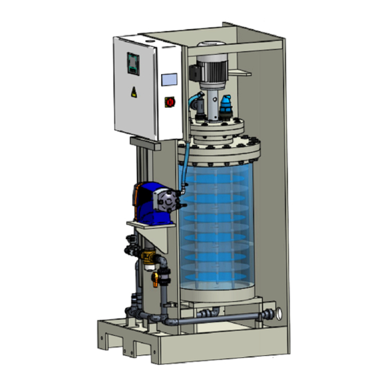
The polymer preparation system DULCODOS ULIa is an inline system and processes liquid polymers to produce a fully activated solution. The polymer preparation system features an integrated mixing and maturing chamber and a peristaltic metering pump. -
Page 8: Technical Details
Function 1.2 Technical details Technical details: Proportional metering as standard 3 system types with different equipment can be selected – basic: manual flow adjustment, manual flushing – medium: automatic flow control, manual flushing – comfort: automatic flow control, automatic flushing Choice of peristaltic or metering pumps: –... -
Page 9: Selectable Components
Function 1.6 Selectable components Selectable components: Preparation output as an inline preparation station or batch preparation station Configuration versions Electrical connection Control versions with or without data communication Operating versions Liquid polymer metering pumps – Peristaltic pump DFXa – Metering pumps gamma/ X –... -
Page 10: Drawing
Function 1.8 Drawing 1.8.1 Drawing of DULCODOS ULIa 400 BASIC A3511 Fig. 3: Drawing of DULCODOS ULIa 400 BASIC Tab. 3: Connectors and connections Pos. Description Material Type Dimension Water supply PVC/FKM Connecting nozzle DN25 Emulsion inlet PVC/FKM Hose line... - Page 11 Function Description Type Dimension Material Part number Raw water pipe DN25 Brass / PVC / Pipes to mixing chamber DN15 PVC / FKM Metering pump for emulsion DFXa 0565 DN10 PUR hose 1116369 PVDF / PTFE Stirrer single-phase, P = 2800 rpm Aluminium frame 1113060...
-
Page 12: Drawing Of Dulcodos Ulia 400 Basic With Post-Dilution
Function 1.8.2 Drawing of DULCODOS ULIa 400 BASIC with post-dilution A3610 Fig. 4: Drawing of DULCODOS ULIa 400 BASIC with post-dilution Tab. 4: Connectors and connections Pos. Description Material Type Dimension Water supply PVC/FKM Connecting nozzle DN25 Emulsion inlet PVC/FKM... - Page 13 Function Description Type Dimension Material Part number Raw water pipe DN25 Brass / PVC / Pipes to mixing chamber DN15 PVC / FKM Metering pump for emulsion DFXa 0565 DN10 PUR hose 1116369 PVDF / PTFE Stirrer single-phase, P = 2800 rpm Aluminium frame 1113060...
-
Page 14: Drawing Of Dulcodos Ulia 400 Medium
Function 1.8.3 Drawing of DULCODOS ULIa 400 MEDIUM A3512 Fig. 5: Drawing of DULCODOS ULIa 400 MEDIUM Tab. 5: Connectors and connections Pos. Description Material Type Dimension Water supply PVC/FKM Connecting nozzle DN25 Emulsion inlet PVC/FKM Hose line DN10 Vent nozzle... - Page 15 Function Description Type Dimension Material Part number Raw water pipe DN25 Brass / PVC / Pipes to mixing chamber DN15 PVC / FKM Metering pump for emulsion DFXa 0565 DN10 PUR hose 1116369 PVDF / PTFE Stirrer single-phase, P = 2800 rpm Aluminium frame 1113060...
-
Page 16: Drawing Of Dulcodos Ulia 400 Medium With Post-Dilution
Function 1.8.4 Drawing of DULCODOS ULIa 400 Medium with post-dilution A3611 Fig. 6: Drawing of DULCODOS ULIa 400 Medium with post-dilution Tab. 6: Connectors and connections Pos. Description Material Type Dimension Water supply PVC/FKM Connecting nozzle DN25 Emulsion inlet PVC/FKM... - Page 17 Function Description Type Dimension Material Part number Raw water pipe DN25 Brass / PVC / Pipes to mixing chamber DN15 PVC / FKM Metering pump for emulsion DFXa 0565 DN10 PUR hose 1116369 PVDF / PTFE Stirrer single-phase, P = 2800 rpm Aluminium frame 1113060...
-
Page 18: Drawing Of Dulcodos Ulia 400 Comfort
Function 1.8.5 Drawing of DULCODOS ULIa 400 COMFORT A3513 Fig. 7: Drawing of DULCODOS ULIa 400 COMFORT Tab. 7: Connectors and connections Pos. Description Material Type Dimension Water supply PVC/FKM Connecting nozzle DN25 Emulsion inlet PVC/FKM Hose line DN10 Vent nozzle... - Page 19 Function Description Type Dimension Material Part number Raw water pipe DN25 Brass / PVC / Pipes to mixing chamber DN15 PVC / FKM Metering pump for emulsion DFXa 0565 DN10 PUR hose 1116369 PVDF / PTFE Stirrer single-phase, P = 2800 rpm Aluminium frame 1113060...
-
Page 20: Drawing Of Dulcodos Ulia 400 Comfort With Post-Dilution
Function 1.8.6 Drawing of DULCODOS ULIa 400 Comfort with post-dilution A3612 Fig. 8: Drawing of DULCODOS ULIa 400 Comfort with post-dilution Tab. 8: Connectors and connections Pos. Description Material Type Dimension Water supply PVC/FKM Connecting nozzle DN25 Emulsion inlet PVC/FKM... - Page 21 Function Description Type Dimension Material Part number Raw water pipe DN25 Brass / PVC / Pipes to mixing chamber DN15 PVC / FKM Metering pump for emulsion DFXa 0565 DN10 PUR hose 1116369 PVDF / PTFE Stirrer single-phase, P = 2800 rpm Aluminium frame 1113060...
-
Page 22: Flow Chart
EMULSION outlet hose DN25 connection DN15 DN15 DN25 DN15 DN25 inlet water DN25 DN25 DN25 DN20 DN25 DN20 DN20 DN10 DN20 DN10 DN10 DN10 DN15 DN15 DN20 drain DN25 DN25 A3613 Fig. 10: P&ID: DULCODOS ULIa 400 BASIC with post-dilution... -
Page 23: P&Id: Dulcodos Ulia 400 Medium
EMULSION outlet hose DN25 connection DN15 DN15 DN25 DN15 DN25 inlet water DN25 DN25 DN25 DN20 DN25 DN20 DN20 DN10 DN20 DN10 DN10 DN10 DN15 DN15 DN20 drain A3614 DN25 DN25 Fig. 12: P&ID: DULCODOS ULIa 400 MEDIUM with post-dilution... -
Page 24: P&Id: Dulcodos Ulia 400 Comfort
EMULSION outlet hose DN25 connection DN15 DN15 DN25 DN15 DN25 inlet water DN25 DN25 DN25 DN20 DN25 DN20 DN20 DN10 DN20 DN10 DN10 DN10 DN15 DN15 DN20 drain A3615 DN25 DN25 Fig. 14: P&ID: DULCODOS ULIa 400 COMFORT with post-dilution... -
Page 25: Identity Code
Identity code Identity code ULIa Type Inline preparation station, 50 ... 100 l/h c=1.0% Inline preparation station, 94 ... 200 l/h c=1.0% Inline preparation station, 188 ... 400 l/h c=1.0% Construction Standard / vertical to the wall Standard / wall-side Mirror image / wall-side Mirror image / vertical to the wall Electrical connection... - Page 26 Identity code fitted for medium + comfort version additional maturing / supply tank with equip‐ ment none Stirrer for maturing /supply tank none Feed pump for maturing / supply tank none Language * Czech German English Spanish Finnish French Italian Portuguese Swedish Chinese...
-
Page 27: Safety And Responsibility
Safety and responsibility Safety and responsibility 3.1 User qualification WARNING! Danger of injury with inadequately qualified per‐ sonnel The operator of the system / equipment is respon‐ sible for ensuring that the qualifications are ful‐ filled. If inadequately qualified personnel work on the unit or loiter in the hazard zone of the unit, this could result in dangers that could cause serious injuries and material damage. -
Page 28: Labelling Of Warning Information
Safety and responsibility 3.2 Labelling of Warning Information Introduction These operating instructions provide information on the technical data and functions of the product. These operating instructions pro‐ vide detailed warning information and are provided as clear step- by-step instructions. The warning information and notes are categorised according to the following scheme. -
Page 29: General Safety Information
Safety and responsibility Type of information Hints on use and additional information. Source of the information. Additional measures. Denotes hints on use and other useful informa‐ – tion. It does not indicate a hazardous or dam‐ aging situation. 3.3 General safety information WARNING! Danger from hazardous substances! Possible consequence: Fatal or very serious inju‐... -
Page 30: Information In The Event Of An Emergency
Safety and responsibility Caution: feed chemical spraying around The metering pump can generate a multiple of its nominal pressure. Hydraulic parts can rupture if a pressure line is blocked. Fit a relief valve or another suitable remedy in the pressure line. -
Page 31: Safety Information
3.6 Safety information Personnel qualification Danger due to incorrect operation of the system Operating personnel must be instructed by a ProMinent service technician. This should be done during initial commissioning. A set of operating instructions must be available beside the system. -
Page 32: Warning Labels
Safety and responsibility 3.7.2 Warning labels A3485 Fig. 16: Warning labels Warning of injury to hands II. Warning of hazardous electrical voltage Test: check whether the labels are still affixed and legible. 3.8 Sound pressure level The sound pressure level is < 70 dB (A), according to DIN EN ISO 11202:2009-11, Acoustics - Noise emission from machinery and equipment. -
Page 33: Storage And Transport
Storage and transport Storage and transport Ä Chapter 3.1 ‘User qualifi‐ User qualification: instructed user cation’ on page 27 . WARNING! Danger from hazardous substances! Possible consequence: Fatal or very serious inju‐ ries. Please ensure when handling hazardous sub‐ stances that you have read the latest safety data sheets provided by the manufacture of the haz‐... -
Page 34: Technical Data
Technical data Technical data 5.1 Technical data for the system System type Max. preparation output / Inline at a con‐ centration of 0.05 – 1.0% Max. preparation output, inline with post- 1800 dilution Maturing time min. Polymer solution concentration Max. raw water pressure Min. -
Page 35: Technical Data For The Pump
Technical data 5.2 Technical data for the pump System type DFXa 0565 0565 0565 Max. dosing rate for concentrations of up to 1.0% (50% active ingredient) Max. dosing rate for concentrations of up to 12.0 1.5% (50% active ingredient) Degree of protection IP 66 IP 66 IP 66... -
Page 36: Construction And Function
Construction and function Construction and function 6.1 Construction of the system All parts of the system designed to mix and mature the liquid con‐ centrate/emulsion are combined to form a single unit. A system consists of the following functional units: A3486 Fig. - Page 37 Construction and function 6.2.1.1 Overview of equipment P_G_0103_SW Fig. 18: Overview of equipment of the DFXa, complete Control unit Drive unit Liquid end P DX 0177 SW_2 Fig. 19: Liquid end DFXa Dosing head Star-shaped screw Insert for hose rupture sensor Suction connector Domed nut on star-shaped screw Pressure connector...
-
Page 38: Point Of Injection
Construction and function 6.2.2 Point of injection The liquid concentrate/emulsion metered by the metering pump is metered into the mixing chamber through a stainless steel spring- loaded injection valve. No water enters the dosing line. No settings are required for the injection valve. The point of injection can be removed and cleaned for maintenance purposes. -
Page 39: Water Apparatus
Construction and function 6.2.3 Water apparatus The water pipework supplies the system with the preparation water for polymer preparation. (Connector A). The ball valve on the inlet side can be used to manually close the feed water line for maintenance work. The pressure reducer with filter insert ensures that the operating pressure is limited and maintained at the correct level. -
Page 40: Mixing Chamber
Construction and function 6.2.4 Mixing chamber WARNING! Danger from hazardous substances! Possible consequence: Fatal or very serious inju‐ ries. Please ensure when handling hazardous sub‐ stances that you have read the latest safety data sheets provided by the manufacture of the haz‐ ardous substance. -
Page 41: Stirrer
Construction and function 6.2.5 Stirrer CAUTION! Automatic start-up The stirrer can start up abruptly once it is con‐ nected to the supply voltage. The system is equipped with an electric stirrer with a speed of approx. 1400 rpm. The electric stirrer is flanged onto the mixing chamber. -
Page 42: Control Cabinet
Construction and function 6.2.7 Control cabinet Alongside the power supply and the fuses, the control cabinet accommodates all the electrical control and command devices nec‐ essary for the operation of the system, such as the PLC and touch panel. The pumps, solenoid valves and control valves are con‐ trolled and fused through the control cabinet. -
Page 43: Optional Assemblies
Construction and function 6.3 Optional assemblies 6.3.1 Option: Post-dilution The post-dilution option enables the output of the system to be specifically increased by the controlled mixing of the polymer solu‐ tion prepared in the mixing chamber with the raw water. This then reduces the concentration of the starting product according to the dilution ratio. -
Page 44: Option: Automatic Flushing
Construction and function Option: Static mixer Included in the scope of delivery: A PVC static mixer DN25/DN40/DN25 – To be connected by the customer at polymer solution outlet “E” of the ULIa – Between the master solution and the post-dilution line to achieve a better mixing result A3852 Fig. -
Page 45: Option: Booster Pump
Construction and function 6.3.4 Option: Booster pump A booster pump must be used for installations with a raw water pressure of < 4.0 bar: Selection by identity code. A minimum pressure of 4.0 bar is generated. The single-phase feed pump is fed with supply voltage, con‐ trolled and monitored by the control. -
Page 46: Assembly And Installation
Assembly and installation Assembly and installation User qualification, mechanical installation: trained and qualified Ä Chapter 3.1 ‘User qualification’ on page 27 personnel, see User qualification, electrical installation: electrical technician, see Ä Chapter 3.1 ‘User qualification’ on page 27 The system is fully factory-assembled. The cabling between the control cabinet and the electrical power units is fully installed. -
Page 47: Installation, Electrical
Assembly and installation 7.3 Installation, electrical Live parts Measure: Disconnect the system from the mains power supply at the electrical connections before carrying out any installation work. Secure the system to prevent it being switched back on again. 7.3.1 Mains power connection Functional faults. -
Page 48: Commissioning
Commissioning Commissioning Ä Chapter 3.1 ‘User qualifica‐ User qualification: trained user tion’ on page 27 Prerequisite for commissioning: All installation and assembly work has been performed by qualified personnel. The system operator has produced system-specific operating guidelines and has trained the operating personnel on the basis of these operating guidelines. -
Page 49: Personal Protective Equipment (Ppe)
Commissioning 8.2 Personal Protective Equipment (PPE) WARNING! Danger from hazardous substances! Possible consequence: Fatal or very serious inju‐ ries. Please ensure when handling hazardous sub‐ stances that you have read the latest safety data sheets provided by the manufacture of the haz‐ ardous substance. -
Page 50: Operation Of The System
Operation of the system Operation of the system A touch panel is fitted to the system. The following functions can be accessed using the touch panel: Visualisation of the control process, Selection of different sub-menus, Calibration of the metering pump, Input and display of parameters, Display of measured values, Display of the setting values of built-in components,... -
Page 51: Display, Detail Screen, Component Status
Operation of the system 9.1.1 Display, detail screen, component status Polymer production with dilution line Login Product Polymer Conc. Capac. Raw water Drain A3618 AUTO ARCHIVES RESET Fig. 33: Display, detail screen, component status Use the two grey arrow keys to switch back and forward between the start screen and the detail screen. - Page 52 Operation of the system Abbreviation Full text Action Backspace deletes the last digit Clear screen clears the entire input Enter input A large screen keyboard appears if letters also need to be entered. Colour codes Tab. 9: Alarm Colour codes Meaning blue no errors...
- Page 53 Operation of the system If the “Login” symbol is displayed at the lower edge of a display, then a “Username” and a “Password” are needed to move to the next display. Tab. 12: The authorisation concept has various access levels: Safety level Username Password...
-
Page 54: User Group Selection Of Functions
Operation of the system 9.2.2 User group selection of functions The following listed functions are available depending on whether Operator or Service user group has been selected. Functions Operator Service Code character Level 1 Level 2 Switch operating mode Perform calibration of the metering pump Change concentration Set liquid concentrate active ingredient Set system output (optional) -
Page 55: Operating Menu: Sub-Menu Construction And Views
Operation of the system 9.3 Operating menu: sub-menu construction and views To open the operating menu, click on ULIa wording, or Triangular symbol Polymer solution production ULIa Parameter Control Calibration Info System Service Menu: Parameter Menu: Control Menu: Calibration Menu: Information Menu: System Menu: Service A3576... -
Page 56: Over Structure Of The Operating Menus
Operation of the system Sub-menu: Control Sub-menu; Control – only the following sub-menus can be changed by operators: Concentration Production Capacity Factory settings Sub-menu; Control – these sub-menus are reserved for Service: Monitoring Valves Booster pump Sub-menu: Service This menu can only be changed by Service. 9.4 Over structure of the operating menus Tab. - Page 57 Operation of the system Operating ULIa Tabs and levels menu Pressure inlet PI2 Control Concentration Active ingredient, Internal/ External setpoint specification, Limit values System output Internal/External setpoint specifi‐ cation, Limit values Control valve VC1 Setting values, operating data, delay times Control valve VC2 Booster pump P1 Factory settings...
-
Page 58: Menu: Parameter
Operation of the system 9.5 Menu: Parameter Stop of production from HMI Parameter MENU: PARAMETER Login PROCESS MEASUREMENT Conc: MOTORS / TRENDS VALVES Capa.: A3577 Archives Fig. 37: Menu: Parameters Sub-menus Process Motors / Valves Measurement Trends 9.5.1 Sub-menu: Process INFO!: The system is pre-configured, and no settings are needed ‘Process’... -
Page 59: Sub-Menu: Measurement
Operation of the system Raw water valve V1 Flushing valve V2 Drain valve V3 Control valve VC1 and VC2 9.5.3 Sub-menu: Measurement INFO!: The system is pre-configured, and no settings are needed in the Measurement sub-menu for start-up. Tab. 16: Sub-menu: Measurement Pressure measurement inlet PI1 Pressure measurement outlet PI2 Raw water flow FIC1... -
Page 60: Control
Operation of the system 9.6 Control Stop of production from HMI Control MENU: CONTROL Login Contr. Valve VC1 Concentration Flow FIC1 Conc: Production Contr. Valve VC2 capacity Flow FIC2 Capa.: Booster pump P1 Pressure PI1 Factory default settings Archives A3578 Fig. -
Page 61: Option: Capacity/System Output
Operation of the system 9.6.2 Option: Capacity/System output Tab. 19: Option: Capacity / System output Capacity setpoint: INTERNAL Setpoint input in l/h Capacity setpoint: EXTERNAL External 4 ... 20 mA signal Capacity actual PV: Display of the current mean value Limit values for warning and error messages Parameters Type... -
Page 62: Calibration
Operation of the system 9.7 Calibration First switch the system to OFF mode. A3579 Fig. 39: Dismantling the injection valve pipework Dismantle the injection valve pipework. Hold the injection valve in a measuring beaker to collect the liquid concentrate. Have scales ready to record the weight of the liquid concen‐ trate. -
Page 63: Information
Operation of the system Enabling calibration Start calibration by pressing [START] . The calibration time is pre-set to 60 seconds but can be changed if required. ð The calibration time starts running after a delay time of 5 ‘Elapsed’ seconds. The countdown is displayed in the field. -
Page 64: Sub-Menu: Statistics
Operation of the system Serial number Inspection date 9.8.2 Sub-menu: Statistics Tab. 22: Sub-menu: Statistics Operating hours Nr. of starts Power failures HMI communication error Polymer production capacity 9.8.3 Sub-menu: Software The Software sub-menu displays the software version of the PLC and HMI. -
Page 65: System
Operation of the system 9.9 System Stop of production from HMI! System MENU: SYSTEM Login CLEAN LANGUAGE DISPLAY Conc: HARDWARE STATISTICS CONFIGURATION Capa.: A3582 Archives Fig. 42: System Tab. 24: System Language settings Date and time Display Hardware Communication / only if selected by the identity code 9.9.1 Sub-menu: Language You can choose from a total of 10 different languages. -
Page 66: Sub-Menu: Communication
Operation of the system 9.9.5 Sub-menu: Communication Ä Chapter 10.15 ‘Option: Modbus/Profibus/Profinet data com‐ munication’ on page 78 9.10 Service Stop of production from HMI! Service Login INPUTS IDENTCODE OUTPUTS Conc: CHANGE FAILURE Capac.: CONTROL COMMISSIONING FAT PROCEDURE MAINTENANCE A3583 ARCHIVES Fig. -
Page 67: Commissioning
Operation of the system 9.10.4 Commissioning Flushing, drainage, pressure build-up process times can be checked and changed 9.10.5 Maintenance display Display of the time to the next maintenance. Then continue with commissioning 9.10.6 FAT procedure Access only for internal checks in the manufacturer’s factory. -
Page 68: Operating Modes
Operating modes Operating modes 10.1 HMI pre-settings Concentration 0.5% typical value, currently max. 1%, 1.5% is technically possible Active ingredient conventional emulsions The raw water flow produces the the max. system configuration value is set at system output with an inline delivery. -
Page 69: Operating Mode: Manual
Operating modes 10.3 Operating mode: MANUAL Manual operation! Main components: Testing and simulation Specific switching on and off Manual operation! PRODUCTION Logout Product Locked Polymer Dilution Water Drain A3626 MANUAL ARCHIVES RESET Fig. 44: OFF/ON Click on the corresponding symbol on the display for the component you wish to test and simulate its function: The sub-menu on the left is displayed. -
Page 70: Off Operating Mode
Operating modes 10.4 OFF operating mode Stop of production from HMI! Stop of production from HMI! Login Product Conc: Polymer Capac.: l/h Dilution Water Drain A3628 RESET ARCHIVES Fig. 46: Stop of production from HMI! Function: Stops production from the HMI. Switch the unit to OFF operating mode. -
Page 71: Start-Up: Procedure Depending On The Type Of System
Operating modes General functionality: The functionality of the unit is visualised on the HMI. Green symbols indicate the all components are working per‐ fectly. Only installed and active components are displayed. ULIa Login Conc: % 0.50 0.50 Capac.: l/h PI1: Bar Tab. - Page 72 Operating modes Medium version: Tab. 27: Combination of manual and automated adjustment Manual settings: Ball valve V2 Drainage Ball valve V3 Product outlet Automated settings: Control valve VC1 Main line to the mixing and maturing chamber Control valve VC2 Post-dilution pipework Comfort version: Tab.
-
Page 73: Start-Up: Basic Version
Operating modes 10.7 Start-up: Basic version Pre-conditions: All connectors connected at the inlets and outlets. Main switch on. Pressure on the display of the unit / PI 1 / left corner of the HMI < 6 bar. Pause function not enabled / jumper to terminals or external signal. -
Page 74: Start-Up: Medium Version
Operating modes 10.8 Start-up: Medium version Pre-conditions: All connectors connected at the inlets and outlets. Main switch on. Pressure on the display of the unit / PI 1 / left corner of the HMI < 6 bar. Pause function not enabled / jumper to terminals or external signal. -
Page 75: Start-Up: Comfort Version
Operating modes Flow display Setpoint and measured value converge after a delay time With post-dilution When post-dilution is installed, the max. output of 400 l/h of the pre‐ pared polymer solution is taken from the main line and the remaining volume of raw water is automatically adjusted using the control valve 10.9 Start-up: Comfort version... -
Page 76: Pause Function
Operating modes Stirrer P2 and pump P3 start. Raw water flows through the system and the liquid polymer is also metered in. 7 Polymer preparation The automatic preparation process starts Motorised valve V3 opens automatically and V2 remains closed Status bar Polymer solution production 8 Polymer solution is fully The “Polymer preparation”... -
Page 77: Archives - Reset
Operating modes PAUSE enabled If the function is PAUSE enabled: Any running polymer preparation process is stopped and – The liquid concentrate pump P3 is stopped. – The solenoid valve for raw water V1 closes. – The stirrer P2 stops. No new preparation is started. -
Page 78: Option: Concentrate Tank Empty Signal
Operating modes 10.13 Option: Concentrate tank empty signal Ä Chapter 6.3.3 ‘Option: Empty signal for con‐ Technical data, see centrate tank’ on page 44 and Ä Chapter 11.3 ‘Setting the liquid concentrate empty signal sensor’ on page 82 . 10.14 Option: Booster pump Ä... -
Page 79: Metering Pump And Additional Components
Metering pump and additional components Metering pump and additional components 11.1 Setting the metering pump INFO!: The system is pre-configured. No settings are needed on the metering pump DFXa. Deviating settings would only distort the control. In the event of a leak, the metering pump can be stopped using the STOP button on the metering pump. - Page 80 Metering pump and additional components The rotating rotor may catch and trap body parts. Only remove the bearing cover once the pump prompts you to do so. Refit the bearing cover once prompted to do so by the pump. ‘Yes’ . Confirm the prompt with ð...
- Page 81 Metering pump and additional components Press the Clickwheel. ‘Run in tube?’ appears. ð ‘Yes’ / ‘No’ [No] exits this macro. Selecting ‘Yes’ is selected. The pump hose (4) is run in if ‘Tube run in ...’ appears. ð The rotor turns a couple of times. ‘Tube change interval’...
-
Page 82: Setting The Liquid Concentrate Empty Signal Sensor
Metering pump and additional components 11.3 Setting the liquid concentrate empty signal sensor The scope of delivery includes: Capacitive switch: CQF16. Bracket: BEF 2 foam pads, 3 mm thick, to mount the pipe. 2 adhesive pads, 1 mm thick, for screwless installation on the surface. - Page 83 Metering pump and additional components Control and display elements A3620 Fig. 53: Display elements Display LED green: Supply voltage enabled Display LED yellow: Switching output Assembly and installation Assembly and dismantling of the sensor in the bracket A3621 Fig. 54: Assembly and dismantling of the sensor in the bracket Assembly and dismantling of the sensor in the bracket.
-
Page 84: Operation Of The System
Operation of the system Operation of the system Ä Chapter 3.1 ‘User User qualification: instructed personnel qualification’ on page 27 WARNING! Danger from hazardous substances! Possible consequence: Fatal or very serious inju‐ ries. Please ensure when handling hazardous sub‐ stances that you have read the latest safety data sheets provided by the manufacture of the haz‐... -
Page 85: Mains Power Switching On And Mains Failure Behaviour
Operation of the system 12.2 Mains power switching on and mains failure behaviour Automatic start-up Each time mains power is switched on, the stirrer starts up without regard to the system statuses measured. Preparation mode can start every time mains power is switched on. If it is necessary to work on the system, disconnect the system from the mains/power supply and secure it to prevent it from being switched back on. -
Page 86: Disposal Of Used Parts
Refer to the Material Safety Data Sheet for your feed chemical. A current Declaration of Decontamination is available to download on the ProMinent website. Sign indicating EU collection system In accordance with the European Directive 2012/19/EU on waste electrical and electronic equipment, this device features the symbol showing a waste bin with a line through it. -
Page 87: Incorrect Operation Of The System
Incorrect operation of the system Incorrect operation of the system The incorrect position of the drainage valves will lead to mal‐ functions. The incorrect position of the shut-off valve in the feed water line will lead to malfunctions. Unauthorised persons must be prevented from entering or changing operating parameters. -
Page 88: Maintenance
Maintenance Maintenance 14.1 Inspecting the metering pump and injection valve Metering pump Inspect the metering pump regularly during operation to ensure that it is working correctly. Check the suction-side and pressure-side connectors. Check that the liquid polymer is being metered; the metering hose is transparent for checking purposes. -
Page 89: Checking The Flow Meter
Maintenance INFO!: You can find more information and the corresponding drawing contained in the solenoid valve operating instructions in the appendix to this documentation. To dismantle the solenoid valve, switch the system to “OFF” operating mode. Manually close the shut-off valve upstream of the pressure reducer Drain the system through ball valve V2 to drain D Undo the 4 socket cap screws on the housing and remove... -
Page 90: Spare Parts
Spare parts Spare parts 15.1 Spare parts list Tab. 29: Spare parts list Pos. Description Part number 0001 Ball valve, VXEIV Ø32 DN25 PVC-U FKM 1114271 0002 Pressure reduction valve, DO 6 F, 1” 302106 0003 Solenoid valve, 6281 G3/4” Ms/FKM 24V 1110210 0004 Pressure sensor, PT5404 0-10bar G1/4”... -
Page 91: Basic Spare Parts
Spare parts 15.2 BASIC spare parts 14 15 A3856 Fig. 55: BASIC spare parts, for spare parts list see: Ä Further information on page 90 15.3 MEDIUM spare parts 14 15 A3857 Fig. 56: MEDIUM spare parts, for spare parts list see: Ä Further information on page 90... -
Page 92: Comfort Spare Parts
Spare parts 15.4 COMFORT spare parts A3858 Fig. 57: COMFORT spare parts, for spare parts list see: Ä Further information on page 90... -
Page 93: Fault Messages
Unspecified faults Should a problem occur, which is not included in this list or should a listed fault not be remedied by the suggested troubleshooting measures, please contact ProMinent Service to remedy the problem. Sensors With every fault analysis, first consider the possibility that a capaci‐... -
Page 94: Important Faults - Cause - Remedy
Fault messages Stop of production, FAULT! Alarm and maintenance history Date Time Login Please change battery - Warning level 1 / No. 8 Conc: Polymer pump P3 not calibrated - Fault level 3 / No. 5 Stirrer P2 - MCB Capac.: l/h Polymer pump P3 not calibrated - Fault level 3 / No. - Page 95 Fault messages Fault message Cause Remedy Prepara‐ tion Stop Pressure sensor PI1 at the Water inlet pressure < 4.0 bar Increase inlet-side pres‐ inlet displays a warning or sure error Correctly adjust pressure reducer or clean filter cup Booster pump option required Digital input faulty Check digital input...
-
Page 96: Data Sheets
Data sheets Data sheets 17.1 Terminal strip signals and logical statuses 17.1.1 Analogue inputs / 4 ... 20 mA Input Signal designation Terminals Description AI 4 Concentration XDC3 Setpoint 4 ... 20 mA = x% - x% AI 5 Capacity XDC3 Setpoint 4 ... -
Page 97: Analogue Outputs / 4
Data sheets 17.1.4 Analogue outputs / 4 ... 20 mA Output Signal designation Terminals Description Emulsion consumption output XDC5 4 ... 20 mA = 4 h polymer pump P3 17.1.5 Digital outputs Output Signal designation Terminals Description Collective alarm XDC4 1-3 0 = Alarm System ready for preparation >... -
Page 98: Control Sequence
Data sheets 17.2 Control sequence Requirement: Successful calibration of the liquid concentrate pump Concentration set 17.2.1 Basic version The ball valves V2 and V3 must be operated manually. Open/close the solenoid valve V1 in manual mode via the HMI. Adjust the system output manually using diaphragm valve VC1. After the start-up process, the mixing chamber and the maturing chamber are always completely filled. -
Page 99: Medium Version
Data sheets 17.2.2 Medium version The ball valves V2 and V3 must be operated manually. Open/close the solenoid valve V1 in manual mode via the HMI. Please use the HMI in manual mode to adjust or close the con‐ trol valve VC1. In AUTO operating mode, the system output is adjusted by the control valve VC1 and controlled by the HMI. -
Page 100: Comfort Version
Data sheets 17.2.3 Comfort version With the Comfort version, the start-up process is enabled by AUTO operating mode. The motorised valves V2 and V3 and the solenoid valve V1 are automatically controlled via the HMI. The system output is adjusted by the control valve VC1 to the specification by the HMI. -
Page 101: Ec Declaration Of Conformity
Tab. 30: Extract from the EC Declaration of Conformity Designation of the product: Automatic preparation system for liquid polyelectrolytes Product type: Dulcodos ULIa 0100-0400 Serial number: see nameplate on the device Relevant EC Directives: EC Machinery Directive (2006/42/EC) -
Page 102: Index
Index Index Action, step by step ......2 Noise level ......48 Ambient conditions . - Page 104 ProMinent GmbH Im Schuhmachergewann 5 - 11 69123 Heidelberg, Germany Telephone: +49 6221 842-0 Fax: +49 6221 842-215 Email: info@prominent.com Internet: www.prominent.com 990379, 1, en_GB © 2023...
Need help?
Do you have a question about the DULCODOS ULIa and is the answer not in the manual?
Questions and answers