Table of Contents
Advertisement
Quick Links
Assembly and operating instructions
Duodos 10
Air-driven double diaphragm pump
EN
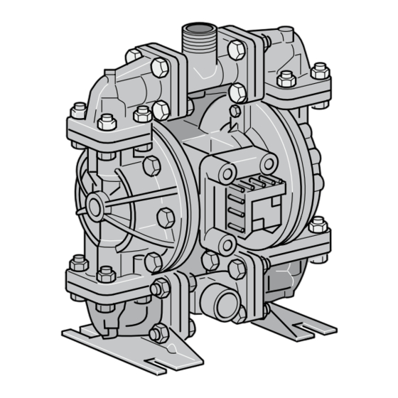
A1136
Please carefully read these operating instructions before use. · Do not discard.
The operator shall be liable for any damage caused by installation or operating errors.
The latest version of the operating instructions are available on our homepage.
Part number 985472
Original Operating Instructions (2006/42/EC)
BA DUO 011 09/16 EN
Advertisement
Table of Contents

Subscribe to Our Youtube Channel
Related Manuals for ProMinent Duodos 10


Summary of Contents for ProMinent Duodos 10
- Page 1 Assembly and operating instructions Duodos 10 Air-driven double diaphragm pump A1136 Please carefully read these operating instructions before use. · Do not discard. The operator shall be liable for any damage caused by installation or operating errors. The latest version of the operating instructions are available on our homepage.
- Page 2 Supplemental instructions General non-discriminatory approach In order to make it easier to read, this document uses the male form in grammatical structures but with an implied neutral sense. It is aimed equally at both men and women. We kindly ask female readers for their understanding in this simplification of the text.
-
Page 3: Table Of Contents
8.3 Maintenance of the pilot valve........23 8.4 Maintenance of the ball valves........24 8.5 Maintenance of the diaphragms......... 25 Disposal of Used Parts............27 Technical Drawing – Duodos 10......... 28 10.1 Exploded drawings and parts lists......29 Spare Parts kits..............33 Technical data..............34 12.1 Performance curves.......... -
Page 4: Function And Identification
PVDF version: -13 ... 93 °C – Viscosity of the medium max. 200 mPas Solids content: none 1.2 Identification Type Housing Diaphragm Feed rate l/h Order numbers Duodos 10 0 ... 900 1010793 Santoprene ® Duodos 10 PVDF 0 ... 900 1010797 Teflon... -
Page 5: Safety And Responsibility
Safety and Responsibility Safety and Responsibility 2.1 Labelling of Warning Information Introduction These operating instructions provide information on the technical data and functions of the product. These operating instructions pro‐ vide detailed warning information and are provided as clear step- by-step instructions. -
Page 6: Users' Qualifications
Electricians must comply with the provisions of the applicable statutory direc‐ tives on accident prevention. Customer Service depart‐ Customer Service department refers to service technicians, who have ment received proven training and have been authorised by ProMinent to work on the system. -
Page 7: Intended Use
Safety and Responsibility Note for the system operator The pertinent accident prevention regulations, as well as all other generally acknowledged safety regulations, must be adhered to! 2.3 Intended use CAUTION! Intended use Possible consequences if the instructions are not observed: Minor injuries and material damage –... - Page 8 Safety and Responsibility WARNING! Hazardous media / contamination of persons and equipment Possible consequence: Fatal or very serious injuries. material damage – Ensure the device is resistant to the media being conveyed – Always observe the safety data sheets for the media to be conveyed.
- Page 9 Safety and Responsibility Maximum pump sound pressure level 91 dB Depending on the operating conditions, the maximum sound pressure level of the device can reach 88 dB ± 3 dB. Bear this in mind and take suitable measures to reduce any impact caused by this sound pressure level.
-
Page 10: Transport And Storage
Transport and storage Transport and storage User qualification, transport and storage: trained user, see Ä Chapter 2.2 ‘Users' qualifications’ on page 6 WARNING! Danger from hazardous substances! Possible consequence: Fatal or very serious injuries. Please ensure when handling hazardous substances that you have read the latest safety data sheets pro‐... -
Page 11: Assembly
Assembly Assembly User qualification, installation: trained qualified personnel, see Ä Chapter 2.2 ‘Users' qualifications’ on page 6 CAUTION! Possible consequence: Slight or minor injuries. Mate‐ rial damage. Observe the permissible ambient conditions. 4.1 Installation surroundings Upright installation Install the double diaphragm pump upright and plumb. The valves of the double diaphragm pump operate when loaded by gravity. -
Page 12: Securing The Double Diaphragm Pump
Assembly 10. 11. 12. 16. 17. 18. A1142 Fig. 1: Installation surroundings Pulsation damper 11. Shut-off valve Flexible connection 12. Compressed air connection Pipe connection 13. Outlet valve Manometer 14. Suction side Shut-off valve 15. Shut-off valve Discharge side 16. Manometer Outlet valve 17. -
Page 13: Ambient Conditions
Assembly 4.2 Ambient conditions NOTICE! Ambient conditions Possible consequence: Property damage and increased wear and tear Assembly is to be carried out in the following order. If the pump has to be installed outdoors, then it is to be equipped with protection against sunlight and weather influences. -
Page 14: Compressed Air Supply
Assembly 4.4 Compressed air supply Compressed air supply The double diaphragm pump must be connected to a compressed air supply in accordance with the current state of the art (ISO 8573-1). We require unoiled, residual oil-free (residual oil from the compressors of maximum 0.1 mg/m³... -
Page 15: Operation Of The Double Diaphragm Pump
Operation of the double diaphragm pump Operation of the double diaphragm pump User qualification: operation instructed personnel, see Ä Chapter 2.2 ‘Users' qualifications’ on page 6 The double diaphragm pump is fully integrated into the customer provided system and is then controlled from this system. It is not possible to operate the double diaphragm pump directly. -
Page 16: Commissioning
Commissioning Commissioning Ä Chapter User qualification, commissioning: trained user, see 2.2 ‘Users' qualifications’ on page 6 Check the fastening elements are correctly seated. Before commissioning the double diaphragm pump, you must check that all fastening elements with sealing rings are correctly seated. The seals may ‘creep’ , so that the fastening elements come loose over time. -
Page 17: Priming
Commissioning 6.2 Priming To start the double diaphragm pump, open the air value by approximately 1/2 to 3/4 of a turn Cavitation If opening of the air valve causes the stroke rate of the double diaphragm pump to increase, but not however the flow volume passing through the double diaphragm pump, then cavitation is the cause. -
Page 18: Checking Tightening Torque Prior To Commissioning
Checking Tightening Torque Prior to Commissioning Checking Tightening Torque Prior to Commissioning Lasting tightness Check that the threaded connectors have the correct torque during commissioning. We also recommend checking these threaded connec‐ tors for correct torque at least once a year because the pump material yields and the tightening torque is then reduced. -
Page 19: Maintenance Of The Double Diaphragm Pump
Maintenance of the double diaphragm pump Maintenance of the double diaphragm pump Ä Chapter User qualification, wait: instructed personnel, see 2.2 ‘Users' qualifications’ on page 6 WARNING! Danger from hazardous substances! Possible consequence: Fatal or very serious injuries. Please ensure when handling hazardous substances that you have read the latest safety data sheets pro‐... -
Page 20: Air Valve Maintenance
Maintenance of the double diaphragm pump Cause: Measure: Air line of too small nominal width Observe the recommendations for dimensioning of the air inlet line in the operating instructions of the double diaphragm pump Air distribution system of the Dismantle and examine the air valve, pilot valve and control pins double diaphragm pump Rigid pipe connections at the Use flexible connections and a pulsation damper... - Page 21 Maintenance of the double diaphragm pump 20 . 23 . 13 . 10 . 14 . 16 . 15 . A1137 Fig. 3: Air valve maintenance Remove the 4 screws (11) Remove the air valve housing (1) Remove the seals (8 and 12). ð...
- Page 22 Maintenance of the double diaphragm pump Push the piston into the control cylinder up to the already mounted end cover. Ensure this does not cause any scratches. Fit the second end stop complete with an O-ring Fit the remaining safety collar Now you can refit the air valve housing in the pump Place the cover (9), the valve house seal (8), the air valve housing (1), with the five rectangular recesses pointing...
-
Page 23: Maintenance Of The Pilot Valve
Maintenance of the double diaphragm pump 8.3 Maintenance of the pilot valve To carry out maintenance on the pilot valve first dis‐ connect the compressed air supply, vent the double diaphragm pump and remove the air supply line from the double diaphragm pump. 20 . -
Page 24: Maintenance Of The Ball Valves
Maintenance of the double diaphragm pump Pull the remaining O-rings (24) onto the piston Screw the outer diaphragm flange, diaphragms and inner dia‐ phragm flange together in a clockwise direction on to the piston rod Fit both tensioning straps 8.4 Maintenance of the ball valves An inspection or maintenance is normally indicated if upon starting the double diaphragm pump: primes badly... -
Page 25: Maintenance Of The Diaphragms
Maintenance of the double diaphragm pump A1138 Fig. 5: Maintenance of the ball valves Unscrew the screws (37) with which the connection fittings are fastened to the pumping housings Check the surfaces of the valve balls (34) and valve seats (33) for wear and damage ð... - Page 26 Maintenance of the double diaphragm pump If necessary remove any liquid which may remain in the double diaphragm pump ð Now the double diaphragm pump can be removed for maintenance. 43. 29. 17. 25. A1139 Fig. 6: Maintenance of the diaphragms Remove both tensioning straps (28) Screw out the outer diaphragm flange (27), diaphragms (26) and inner diaphragm flange (25) together in an anti-clockwise...
-
Page 27: Disposal Of Used Parts
Decontaminate the unit before returning it for repair. To do so, remove all traces of hazardous substances. Refer to the Material Safety Data Sheet for your feed chemical. A current Declaration of Decontamination is available to download on the ProMinent website. -
Page 28: Technical Drawing - Duodos 10
Technical Drawing – Duodos 10 Technical Drawing – Duodos 10 III. A1140 Fig. 7: Technical Drawing – Duodos 10 Suction connector III. Optional II. Discharge connector IV. Compressed air connector... -
Page 29: Exploded Drawings And Parts Lists
Technical Drawing – Duodos 10 10.1 Exploded drawings and parts lists Exploded drawing – Duodos 10 PP A1141 Fig. 8: Exploded drawing – Duodos 10 Parts list Duodos 10 PP Item Quan‐ Part no. Reference Description Remark tity 1043218 095-077-551... - Page 30 Technical Drawing – Duodos 10 Item Quan‐ Part no. Reference Description Remark tity 1043256 165-073-551 Cover, silencer Polypropylene, glass fibre- reinforced 1043128 545-003-115 Hexagon head screw 1/4-20 Stainless steel 302/304 1043110 449-021-551 Packing gland insert Polypropylene, glass fibre- reinforced 1043250...
- Page 31 Technical Drawing – Duodos 10 Parts list Duodos 10 PVDF Item Quan‐ Part no. Reference no. Description Remark tity 1043218 095-077-551 Air valve housing Polypropylene, glass fibre- reinforced 1043113 031-106-000 Control cylinder and piston, air Subassembly valve 1043183 560-101-360 O-ring...
- Page 32 Technical Drawing – Duodos 10 Item Quan‐ Part no. Reference no. Description Remark tity 1043085 722-073-520 Valve seat PVDF 1043101 050-034-600 Valve ball PTFE 1043146 312-095-520 Elbow, suction side PVDF 1043126 706-023-115 Hexagon head screw 10-32 Stainless steel 302/304 UNF x 1"...
-
Page 33: Spare Parts Kits
1043250 720-031-359 Seal, K-R Polyurethane 1043222 755-038-000 Piston, pilot valve Subassembly 1043221 775-038-000 Cylinder, pilot valve Subassembly Spare parts kit liquid end for Duodos 10 PP (order no. 1010801): Part no. Reference Description Remark ntity 1043101 050-033-354 Valve ball Santoprene ®... -
Page 34: Technical Data
Technical data Technical data Technical data – Duodos PP / PVDF Order no. 1010793 1010797 Pump type Duodos 10 PP Duodos 10 PVDF Capacity (max.) 900 l/h 900 l/h Back pressure (max.) 70 m water column 70 m water column Feed rate/stroke 0.04 l... - Page 35 Chemically inactive and effectively impermeable. Only a very few chemicals are know to react with Teflon ® PVDF -13 °C 93 °C Polypropylene 5 °C 65 °C Repair tools Tool Size Duodos 10 Spanner 3/8" 9.52 mm Spanner 7/16" 11.11 mm Spanner 1/2" 12.7 mm Screw driver 7 mm 7.00 mm...
-
Page 36: Performance Curves
The performance curves are based on the pumping of water at ambient temperature (approx. 20 °C). A1160 Fig. 9: Performance curve of Duodos 10 / Maximum air consumption 11 m³/h Delivery height (m water column) II. Pump capacity in l/h... -
Page 37: Declaration Of Conformity
In accordance with DIRECTIVE 2006/42/EC OF THE EUROPEAN PARLIAMENT AND OF THE COUNCIL, Appendix I, BASIC HEALTH AND SAFETY REQUIREMENTS, section 1.7.4.2. C. ProMinent GmbH Im Schuhmachergewann 5 - 11 D - 69123 Heidelberg, Germany, hereby declare that the product specified in the following, complies... -
Page 38: Index
Index Index Action, step by step ......2 Operation in the open air and outdoors ..8 Applied harmonised standards . - Page 40 ProMinent GmbH Im Schuhmachergewann 5 - 11 69123 Heidelberg, Germany Telephone: +49 6221 842-0 Fax: +49 6221 842-419 Email: info@prominent.com Internet: www.prominent.com 985472, 3, en_GB © 2016...
Need help?
Do you have a question about the Duodos 10 and is the answer not in the manual?
Questions and answers