Table of Contents
Advertisement
Quick Links
Operating instructions
Peristaltic metering pump
DULCO flex Control - DFYa
EN
Please carefully read these operating instructions before use. · Do not discard.
The operator shall be liable for any damage caused by installation or operating errors.
The latest version of the operating instructions are available on our homepage.
Part no. 981307
Original operating instructions (2006/42/EC)
BA DX 030 05/20 EN
Advertisement
Table of Contents

Subscribe to Our Youtube Channel
Related Manuals for ProMinent DULCO flex Control-DFYa


Summary of Contents for ProMinent DULCO flex Control-DFYa
- Page 1 Operating instructions Peristaltic metering pump DULCO flex Control - DFYa Please carefully read these operating instructions before use. · Do not discard. The operator shall be liable for any damage caused by installation or operating errors. The latest version of the operating instructions are available on our homepage. Part no.
- Page 2 Supplemental directives Supplementary information Read the following supplementary information in its entirety! You will ben‐ efit more from the operating instructions should you already know this information. The following are highlighted separately in the document: Enumerated lists Fig. 1: Please read! Instructions ð...
-
Page 3: Table Of Contents
Table of contents Table of contents Identity code..................6 About this pump................9 Safety chapter................10 Storage, transport and unpacking..........16 Overview of equipment and control elements....... 17 5.1 Overview of equipment............17 5.2 Control elements..............18 5.2.1 Control elements, Description..........19 5.2.2 Key functions.............. - Page 4 Table of contents 12.4.2 Setting the timer............... 57 12.4.3 Clear all................63 12.4.4 Examples................. 63 12.4.5 Timer information............. 64 12.4.6 Typical pitfalls Timer functional faults......64 12.4.7 Brief explanation of selected functions......65 ‘Service’ ................68 12.5 ‘Access protection’ ............69 12.5.1 12.5.2 ‘Password ’...
- Page 5 Table of contents Installation instructions: Retrofitting Relays ........ 108 Index.................... 110...
-
Page 6: Identity Code
E PVDF, NPT 3/4" F PVC, NPT 3/4" G TRI-CLAMP, VA, 1" H DIN 11851, VA, NW20 Hose rupture indicator without hose rupture indicator with hose rupture indicator Design P ProMinent version M modified Special version 0 Standard H Chemically high-resistance version (Halar-coated) - Page 7 Identity code Product range DULCO flex Control - DFYa Logo with logo without logo M modified Version of power unit U universal 100 ... 230 V ± 10 %, 50/60 Hz Cable and plug A 2 m, Europe B 2 m, Switzerland C 2 m, Australia D 2 m, USA / 115 V E 2 m, Great Britain...
- Page 8 Identity code Product range DULCO flex Control - DFYa Spanish French...
-
Page 9: About This Pump
About this pump About this pump About this pump Pumps in the DULCO flex Control - DFYa product range are microproc‐ essor-controlled peristaltic metering pumps with the following characteris‐ tics: Simple adjustment of the capacity directly in l/h or in gph Flow reversal possible Simpler hose replacement supported by software Only the medium comes into contact with the hose... -
Page 10: Safety Chapter
Observe the general limitations with regard to viscosity limits, chem‐ ical resistance and density - see also ProMinent resistance list in the Product Catalogue or at www.prominent.com! Use the "Resistance list for DULCO flex Control DFXa and DFYa” available at www.promi‐... - Page 11 Safety chapter Safety information WARNING! Warning about personal and material damage The pump can start to pump, as soon as it is connected to the mains voltage. – Install an emergency cut-off switch in the pump power supply line or integrate the pump in the emer‐ gency cut-off management of the system.
- Page 12 An unsuitable feed chemical can damage the parts of the pump that come into contact with the chemical. – Take into account the resistance of the wetted mate‐ rials and the ProMinent Resistance List when selecting the feed chemical - see the ProMinent Product Catalogue or visit ProMinent.
- Page 13 Customers should only remove the front cover of the liquid end in accord‐ ance with the "Repair" chapter. Only ProMinent Service is authorised to open the housing in the pump foot and the HMI (houses the control elements). Other protective equipment...
- Page 14 Safety chapter WARNING! – A warning sign indicating "Warning of injury to hands" is stuck on the pump and warns of rotating parts and the risk of being dragged into the liquid end. – Ensure that the label is always fitted and legible. Star-shaped handle with locking nut WARNING! –...
- Page 15 Service The service department refers to service technicians, who have received proven training and have been authorised by ProMinent to work on the device / system. Sound pressure level Sound pressure level LpA < 70 dB according to EN ISO 20361...
-
Page 16: Storage, Transport And Unpacking
Storage, transport and unpacking Storage, transport and unpacking Ä ‘Qualification of personnel’ User qualification: Instructed person - see on page 14 Safety information WARNING! Only return metering pumps for repair in a cleaned state and with a flushed liquid end - refer to "Decommis‐ sioning! Only return metering pumps with a completed Decon‐... -
Page 17: Overview Of Equipment And Control Elements
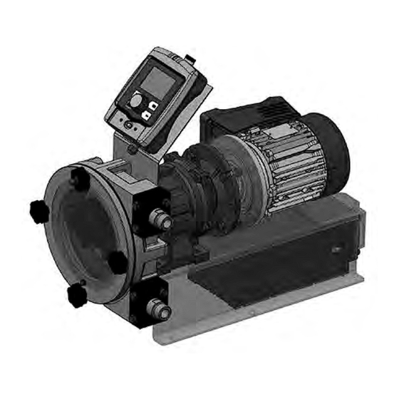
Overview of equipment and control elements Overview of equipment and control elements 5.1 Overview of equipment B1171 Fig. 2: Overview of equipment DFYa, complete Liquid end Motor Control unit (in the pump foot) Gear B1173 Fig. 3: Liquid end of DFYa Front cover (transparent) Star screw Dosing head... -
Page 18: Control Elements
Overview of equipment and control elements 5.2 Control elements Control elements, overview P_SI_0180_SW Fig. 4: HMI control elements DULCO flex Control - DFYa DFYa LCD screen [Menu] key Clickwheel [Priming] key [STOP/START] key [Back] key "Bluetooth active” display (blue) Fault indicator (red) Warning indicator (yellow) 10 Operating indicator (green) P_DX_0072_SW... -
Page 19: Control Elements, Description
Overview of equipment and control elements “Hose rupture” socket (DFM input) "Level switch" terminal LEDs (as ) and CAN bus status LED (external) 5.2.1 Control elements, Description Use this overview to familiarise yourself with the keys and other control elements on the pump! Identifier and fault displays on the LCD screen ANALOG... - Page 20 Overview of equipment and control elements Refer to the chapter entitled "Main displays and secondary displays" in the Appendix for the different main displays and secondary displays. The LCD screen supports the operation and adjustment of the pump using various information and identifiers: MANUAL MANUAL Level...
-
Page 21: Key Functions
Overview of equipment and control elements Identifier Meaning The pump is in ‘ANALOG’ operating mode. ‘Curve è linear’ type of processing is set. ‘ANALOG’ operating mode. The pump is in ‘Curve è Upper side band’ type of processing is set. A hose rupture indicator is connected. - Page 22 Overview of equipment and control elements * When priming the pump does not run at maximum number of revolutions. [Priming] is pressed in ‘Stop’ state, then [Priming] has top priority as long as the button is pressed. Refer to the "Set-up basics" chapter for information on how to adjust figures...
-
Page 23: Functional Description
Functional description Functional description 6.1 Device An electric motor drives a rotor. Rollers are fitted to the ends of the rotors, which press the pump hose against the inner curvature of the dosing head. The peristaltic pump operates by the rollers driving the feed chem‐ ical through the pump hose. -
Page 24: Relay (Options)
Functional description ‘Settings’ menu: The following functions can be selected using the "Calibrate" function Calibrate the pump if you wish good precision when metering high-vis‐ cosity feed chemicals. ‘menu’ "Auxiliary capacity” function This facilitates the switch-over to a fixed adjustable capacity in the via the "External control"... -
Page 25: Led Displays
Functional description 6.6 LED displays LED display Colour lights up flashes Fault indicator A fault message is undefined oper‐ pending ating status Warning indicator yellow A warning message is pending Operating display Green The pump is ready for operation During every revolution: Capacity greater than 10 l / h During every 1/2 revolu‐... - Page 26 Functional description The following list shows the order: 1. - Priming 2. - Error 3. - Stop 4. - Pause 5. - Warning 6. - Auxiliary frequency 7. - Manual, Analogue, Contact, Batch Comments: “Priming" can take place in any pump mode (providing it is working). An "error”...
-
Page 27: Assembly
Assembly Assembly Ä ‘Qualification User qualification: Technical personnel and service - see of personnel’ on page 14 Compare the dimensions on the dimensional drawing in the appendix and on the pump. Space requirement CAUTION! Danger from incorrectly operated or inadequately main‐ tained pumps Danger can arise from a poorly accessible pump due to incorrect operation and poor maintenance. -
Page 28: Setting The Roller Pressure
Assembly It is recommended to use a flexible transition between two fixed pipes and the hydraulic connection of the pump, in order to avoid the transmission of vibrations. 7.3 Setting the roller pressure Introduction When delivered, a roll is supplied unfitted (for an improved hose storage period). - Page 29 Assembly ** The number of spacer plates for Norprene ® is always 9 – you need to do nothing more. Note that you will change the identity code of the pump by changing the number of spacer plates. Changing the number of spacer plates – ‘Hose change’...
- Page 30 Assembly WARNING! The rotating rotor may catch, trap and wind body parts or clothing. – Only remove the front cover when the pump prompts you to do so. – Only refit the front cover when the pump prompts you to do so. ‘Yes’...
-
Page 31: Mounting The Hmi User Control
Assembly Fit the front cover (1) and attach the 4 star-shaped screws (2) to the dosing head (5). Screw the domed nut onto the 4th star screw again and tighten it to provide a locking function. Press the Clickwheel. ‘Hose change interval’ menu appears. ð... - Page 32 Assembly Install the HMI in the immediate vicinity of the pump. If not provided for, fit a circuit breaker there - refer to the "Installation, electrical" chapter. Ensure that the system is set up ergonomically. When doing so, consider the available cable length. Prevent tripping haz‐ ards.
-
Page 33: Installation, Hydraulic
– Take into account the resistance of the wetted mate‐ rials and the ProMinent Resistance List when selecting the feed chemical - see the ProMinent Product Catalogue or visit ProMinent. CAUTION! Warning of feed chemical spraying around An unsuitable feed chemical may cause premature wear to the pump hose. - Page 34 The use of untested third party components can result in injury to personnel and material damage. – Only fit parts to metering pumps that have been tested and recommended by ProMinent. CAUTION! Warning of feed chemical spraying around The pipes can become loose or rupture if they are not installed correctly.
-
Page 35: Installation, Electrical
Installation, electrical Installation, electrical Ä ‘Qualification of personnel’ User qualification: Electrical technician - see on page 14 WARNING! Danger of electric shock A mains voltage may exist inside the device. – Before any work, disconnect the device's mains cable from the mains. WARNING! Risk of electric shock This pump is supplied with a grounding conductor and a... -
Page 36: Hmi Operating Unit
Installation, electrical CAUTION! Material damage possible due to power surges Should the pump be connected to the mains power supply in parallel to inductive consumers (such as sole‐ noid valves, motors), inductive power surges can damage the control when it is switched off. –... -
Page 37: Supply Voltage Connector - Mains Voltage
Installation, electrical 9.2 Supply voltage connector - mains voltage WARNING! Unexpected start-up is possible The pump can start pumping and consequently feed chemical may escape as soon as the pump is connected to the mains/power supply. – Avoid the escape of feed chemical. –... - Page 38 Installation, electrical Electrical interface for pin 1 "Pause" - pin 2 "External contact" - pin 5 "Aux‐ iliary capacity" Data Value Unit Voltage with open contacts Input resistance 10 kΩ Max. pulse frequency 25 pulse/s Min. pulse duration 20 ms P_BE_0014_SW Control via: Fig.
-
Page 39: Level Switch" Terminal
Installation, electrical "Analog" operating mode The pump capacity and/or number of revolutions can be controlled by a current signal. The current signal is connected between pin 3 and pin 4. Pin 1 and pin 4 must also be connected. “Auxiliary capacity” operating mode The pump works at a pre-set capacity if: Pin 5 and pin 4 are connected to each other. -
Page 40: Relay
Installation, electrical Function 4-wire cable Power supply (5 V) brown Coding white Feedback blue Earth GND black P_DE_0010_SW Fig. 16: Assignment on the cable 9.3.4 Relay 9.3.4.1 Relay functions Tab. 3: DULCO flex Control - DFYa DFYa Identity code Designation Maximum voltage Maximum current no relay... - Page 41 Installation, electrical Identity code “1” To pin VDE cable Contact CSA cable white N/O (normally open) white Green N/C (normally closed) brown C (common) black P_G_0072_SW Fig. 18: Assignment on the pump 9.3.4.3 Output for other relays (identity code “3”) A fault indicating and a pacing relay can be ordered as options - refer to ordering information in the appendix.
- Page 42 Installation, electrical The variable to be signalled for the current output can be selected in the ‘ANALOG OUTPUT’ menu. The current output plus relay can be retrofitted and operates once it is plugged into the board. Electrical interface for current output Data Value Unit Open circuit voltage:...
-
Page 43: Initial Commissioning
Initial commissioning Initial commissioning Ä ‘Qualification User qualification: Technical personnel and service - see of personnel’ on page 14 10.1 Testing prior to commissioning the pump The following checks are to be carried out: Ensure that the pump has not been damaged during transportation or storage. -
Page 44: Basic Set-Up Principles
Basic set-up principles Basic set-up principles Please also refer to all the overviews covering – "Operating/set-up overview" and "Operating menu for DULCO flex Control - DFYa, complete" in the appendix and the "Overview of equipment and con‐ trol elements" and "Control elements” chapters. The pump exits the menu and returns to a contin‐... - Page 45 Basic set-up principles Confirming an entry [Clickwheel] . Briefly press the ð The software switches to the next menu point or back to the menu and saves the entry. Exiting a menu option without confirming it [Back] . Press ð The software switches to the next menu point or back to the menu without saving anything.
-
Page 46: Checking Adjustable Variables
Basic set-up principles Confirming adjustable variables [Clickwheel] 1x. Press the ð The software saves the entry. 11.2 Checking adjustable variables Continuous displays Before adjusting the pump, you can check the current settings of the adjustable variables: [Clickwheel] if the pump is showing a continuous Simply turn the display. -
Page 47: Set Up / 'Menu
‘Menu’ Set up / ‘Menu’ Set up / Ä ‘Qualification User qualification: Technical personnel and service - see of personnel’ on page 14 Refer to all overviews covering "Operating/set up – overview" and "Operating menu DULCO flex Control - DFYa, complete" in the appendix and in the chap‐ ters "Overview of equipment”... -
Page 48: Operating Mode
‘Menu’ Set up / ‘Operating mode’ 12.2.1 ‘Menu / Information è Operating mode è ...’ ‘Manual’ 12.2.1.1 ‘Menu / Information è Operating mode è Manual’ ‘Manual’ operating mode lets you operate the pump manually. The capacity can be set in the continuous displays of this operating mode. The minimum volume that can be metered corresponds to 1 revolution of the rotor. - Page 49 ‘Menu’ Set up / ‘Batch’ operating mode enables you to pre-select large metering vol‐ umes or metering times. [Clickwheel] if you have You can trigger the metering volume using the ‘Push’ continuous display. You can also trigger already switched to the them via a pulse using the "External control"...
- Page 50 ‘Menu’ Set up / ‘Curve’ and ‘Curve points’ to define current signal speed “Extended” menu: You can use curves in the same way as: ‘Linear curve ’ ‘Lower side band’ ‘Upper side band’ ‘Linear curve’ The "Linear curve" symbol appears on the LCD screen. You can enter any speed behaviour proportional to the current signal.
-
Page 51: Dosing Direction
‘Menu’ Set up / I [mA] I [mA] B0089 Fig. 27: Speed-current diagram for a) Lower side band, b) Upper side band ‘Upper side band’ Using this processing type, you can control a metering pump using the current signal as shown in the diagram above. ‘Lower side band’... -
Page 52: Calibration
‘Menu’ Set up / The pump displays the current load number, which is simply a number between 0 and 99, in the ‘Load’ secondary display. The number depends on factors, such as: back pressure, temperature, feed chemical viscosity, hose material, ..Normally there is no need to calibrate anything here. -
Page 53: Inputs/Outputs
‘Menu’ Set up / Lead the suction hose into a measuring cylinder containing the feed chemical – make sure that the discharge hose is installed perma‐ nently (operating pressure, ...!). [Priming] ) if the suction hose is Prime the feed chemical (press ... - Page 54 ‘Menu’ Set up / ‘Auxiliary capacity’ It can be activated via the "External control" socket. If is being used, then the "AUX” identifier appears on the LCD screen. Refer to the "Hierarchy of Operating Modes, Functions and Fault Statuses" for the order of the various operating modes, functions and fault statuses. ‘Relay1 (optional)’...
-
Page 55: System
‘Menu’ Set up / ‘Relay2 (optional)’ 12.2.5.3 ‘Menu / Information è Settings è Inputs/outputs è Relay2 è ...’ ‘Relay2’ - see Ä Chapter 12.2.5 ‘Inputs/outputs’ For more information on on page 53 . ‘mA-Output (optional)’ 12.2.5.4 ‘Menu / Information è Settings è Inputs/outputs è mA-Output ...’... -
Page 56: Set Time
‘Menu’ Set up / 12.2.6.1 Volume unit ‘Menu / Information è Settings è System è Volume unit è ...’ ‘Volume unit’ sub-menu. You can select another unit for the volume in the ‘Set time’ 12.2.7 ‘Menu / Information è Settings è Set time è ...’ ‘Set time’... -
Page 57: Activation / Deactivation
‘Menu’ Set up / allow the pump to work at a defined capacity stop / start the pump ‘Batch (time)’ ) trigger a batch ( 12.4.1 Activation / deactivation ‘Menu / Information è Timer è Activation è ...’ You can only program the timer when ‘Activation’ is set to ‘inactive’... - Page 58 ‘Menu’ Set up / The following administration functions are available to manage the com‐ mands (program lines): ‘New’ ) 1 - Reprogram program line ( ‘Show’ ) 2 - Check program line ( ‘Change’ ) 3 - Change program line ( ‘Clear’...
- Page 59 ‘Menu’ Set up / Instruction 03/05 workdays 1 (Mo-Fr) 12:00 Manual 20.00 l/h B1106 Example Time event (trigger) Action workdays 1 (Mo-Fr) Time of day 12:00 Manual 20.00 l/h The example means: ‘Manual’ When it is 12:00 on a workday, then the pump is to work in operating mode at 20.00 l/h.
- Page 60 ‘Menu’ Set up / Tab. 9: Selected value ranges Designation Value range Line numbers 01 ... 32 Day (date) 01 ... 28 Time of day (hours) 00 ... 23 seconds 0001 ... 9999 ‘Init’ Initial conditions 12.4.2.1.2 ‘Init’ initial conditions can be set at the begin‐ Using the triggering event ning of a program sequence.
- Page 61 ‘Menu’ Set up / CAUTION! If you wish to use automatic summer time adjustment ‘Settings’ - ‘Time’ ) avoid in principle any time events between 02:00 and 03:00. A time event lets you trigger an action precisely to the minute. 12.4.2.2 1 time event - several actions You can assign 1 time event to several actions.
- Page 62 ‘Menu’ Set up / [Clickwheel] . Turn the ð Scroll from instruction to instruction. The number of the program line or instruction (and the number of the last program line or instruction) appears at the top in the dark bar. Pressing the [Clickwheel] returns you to ‘Set timer’...
-
Page 63: Clear All
‘Menu’ Set up / 12.4.3 Clear all ‘Menu / Information è Timer è Clear all è ...’ ‘Clear all’ menu to clear all instructions (the entire program). Use the 12.4.4 Examples Requirements: You have already worked with the pump type ‘Settings è... -
Page 64: Timer Information
‘Menu’ Set up / Test your programming! The secondary display “Timer” can help here, which shows the next instruction and the remaining time. (To access this secondary [Clickwheel] in a continuous display until a long display, press the series of small circles appears below - immediately turn the [Clickwheel] to navigate to the last circle and press the [Clickwheel] .) The continuous display itself shows information on the current... -
Page 65: Brief Explanation Of Selected Functions
‘Menu’ Set up / 12.4.7 Brief explanation of selected functions Time event (trigger) An event can be triggered either time-dependent or event-controlled. 1 - Time events (really time-dependent) are processed precisely to the minute. ‘Init’ ) is executed at the start of the program ( ‘Timer 2 - Initialisation ( Activation è... - Page 66 ‘Menu’ Set up / B1081 Fig. 28: Bar chart - Template...
- Page 67 ‘Menu’ Set up / B1082 Fig. 29: Switching times - Template...
-
Page 68: Service
‘Menu’ Set up / Tab. 12: Discard program lines / instructions about the program (Line 09 = example) Instruction no. Time event Action workdays (Mo-Fr) 15:23 Contact ‘Service’ 12.5 ‘Menu / Information è Service è ...’... -
Page 69: Access Protection
‘Menu’ Set up / ‘Service’ menu is split into the following sub-menus: ‘Access protection’ ‘Password’ ‘Hose’ ‘Clear counters’ ‘Log book’ ‘Display’ ‘HMI logout’ ‘Access protection’ 12.5.1 ‘Menu / Information è Service è Access protection è ...’ You can lock parts of the setting options here. The following locking options are available: Selection Point ①... -
Page 70: Password
‘Menu’ Set up / ‘Password ’ 12.5.2 ‘Menu / Information è Service è Password è ...’ ‘Change password’ menu. You can enter a password of your choice in the ‘Hose’ 12.5.3 ‘Menu / Information è Service è Hose è ...’ [STOP/START] to bring the pump to a For this menu to appear, press stop (manually). -
Page 71: Clear Counters
‘Menu’ Set up / ‘Clear counters’ 12.5.4 ‘Menu / Information è Service è Clear counters è ...’ ‘Clear counters’ menu: You can reset the counters to "0" in the ‘All’ ‘Revolutions counter’ ‘Volume counter’ (total litres) To clear: exit the menu by briefly pressing the [Clickwheel] . -
Page 72: Language
‘Menu’ Set up / You can log off the HMI from the internal pump CAN bus here. ‘Language’ 12.6 ‘Menu / Information è Language è ...’ ‘Language’ menu. You can select the desired operating language in the... -
Page 73: Operation
Operation Operation Ä ‘Qualification of personnel’ User qualification: Instructed person - see on page 14 This chapter describes all the operating options in a continuous display (several symbols and the pressure display appear at the top in the black bar) for the person trained on the pump. Please also refer to the "Operating/Setting overview"... - Page 74 Operation List of adjustable variables: Dos. capacity Contact volume Batch dosing time Batch start Time Change directly adjustable variables Changing a variable in the relevant contin‐ Press the [Clickwheel] . uous display: ð The variable can be changed (highlighted). [Clickwheel] . Turn the ð...
-
Page 75: Maintenance
Maintenance Maintenance Ä ‘Qualification User qualification: Technical personnel and service - see of personnel’ on page 14 Maintenance information WARNING! It is mandatory that you read the safety information and specifications in the "Storage, Transport and Unpacking" chapter prior to shipping the pump. CAUTION! Warning of feed chemical spraying around Feed chemical may spray out of the hydraulic compo‐... - Page 76 Maintenance Maintenance intervals Interval Maintenance work Personnel Quarterly* Check the pump hose for damage** - refer to Ä Chapter 14.1 ‘Replacing Technical personnel the pump hose’ on page 77 . Clean running surface in the dosing head and rotor rollers. You may need to carefully but fully remove any adhered hose residue with a plastic or wooden scraper.
-
Page 77: Replacing The Pump Hose
Maintenance 14.1 Replacing the pump hose Ä ‘Qualification User qualification: Technical personnel and service - see of personnel’ on page 14 WARNING! The rotating rotor may catch and trap body parts. – Only replace the pump hose as outlined in the instructions below. - Page 78 Maintenance ‘Hose change’ menu. Go to the ‘Go to change position?’ appears. ð WARNING! The rotating rotor may catch, trap or drag in body parts or clothing. – Only remove the front cover (1) when the pump prompts you to do so. –...
-
Page 79: Cleaning Hose Rupture Indicator (Option)
Maintenance ‘Hose change - Step 3’ - ‘Insert roller and The rotor stops and cover again’ appears. If the position is not ideaI (the space for the roller to be fitted should be quite far from the hose), move the rotor into the right [Clickwheel] . -
Page 80: Repair
WARNING! Danger of electric shock Unauthorised repairs inside the pump may result in an electric shock. For this reason, only allow a ProMinent branch or repre‐ sentative to perform repairs inside the pump, in partic‐ ular the following: – Replacement of damaged mains connection lines –... -
Page 81: Troubleshooting
Troubleshooting Troubleshooting Ä ‘Qualification of personnel’ User qualifications - see following table and on page 14 Safety information WARNING! Warning of hazardous feed chemical Should a dangerous feed chemical be used: it may escape from the hydraulic components when working on the pump, material failure or incorrect handling of the pump. - Page 82 Troubleshooting Error Possible cause Remedy The diameter on the suction side is Increase the diameter of the suction insufficient. side, where this is possible. The suction line is too long Shorten the suction line where this is possible. The feed chemical viscosity is too Reduce the viscosity where this is high.
-
Page 83: Faults With Error Message
Troubleshooting 16.2 Faults with error message 16.2.1 Fault messages on the LCD screen In the event of a fault: the red LED display lights up. an identifier “Error” , an identifier shown below and a message appear on the LCD screen. the pump stops. - Page 84 Troubleshooting Fault description Cause Remedy Personnel The options module is 1. Check whether the module is cor‐ Technical per‐ No. 45: The identifier and the ‘Module error’ appear. message missing or no communica‐ rectly installed. sonnel tion is established 2. Call Service. between the options module and the pump electronics.
- Page 85 Troubleshooting Fault description Cause Remedy Personnel The pump has detected 1. Press the [Clickwheel] (think of the Technical per‐ No. 59: The identifier appears followed by the message too high a back pressure. consequences for the process!). sonnel ‘Overload FC’ . (Slow overpres‐ 2.
-
Page 86: Warning Messages On The Lcd Screen
Troubleshooting Fault description Cause Remedy Personnel 2. Check whether the pump hose is The temperature at the Technical per‐ No. 47: The identifier appears too cold. followed by the message PFC is too high. sonnel ‘Temperature error’ . 3. Check whether the ambient tem‐ perature is too high. -
Page 87: All Other Faults
Troubleshooting 16.2.3 All other faults Please contact the responsible ProMinent branch or representative! 16.3 Log book 16.3.1 Fault messages in the log book For more information on the ‘ERROR’ messages - refer to the chapter "Fault messages on the LCD screen”. -
Page 88: Event Messages In The Log Book
Troubleshooting Tab. 15: Warnings Log book no. Description The temperature in the PFC is too high. The FC is overloaded. The temperature in the FC is too high. The feed chemical reaches “Warning” level. The hose lifetime reaches “Hose-warning” point. An HMI was connected to a CANopen pump. -
Page 89: Decommissioning And Disposal
Decommissioning and disposal Decommissioning and disposal Ä ‘Qualification User qualification: Technical personnel and service - see of personnel’ on page 14 Decommissioning WARNING! Danger from chemical residue There is normally chemical residue in the liquid end and on the housing after operation. This chemical residue could be hazardous to people. - Page 90 Decommissioning and disposal Disposal CAUTION! Risk to the environment from the battery There is a battery in the pump, which can have a toxic effect on the environment. – Disconnect the battery from the remaining parts. – Note the pertinent regulations currently applicable in your country! CAUTION! Environmental hazard due to gear oil...
-
Page 91: Technical Data
Technical data Technical data WARNING! Risk of personal injuries Please observe the ”Supplement for modified version“ at the end of the chapter! It replaces and supplements the technical data! 18.1 Performance data DULCO flex Control - DFYa, DFYa at 80 Liquid Minimum capacity Speed, max. -
Page 92: Material Specifications
Technical data 18.4 Material specifications Part Material Pump hose * NR, NBR, EPDM, NBR-A Hypalon or Norprene ® ® Hose connection * VA, PP, PVDF or PVC-U ** Pump housing Aluminium EN-AC-44100 Front cover Steel F-111 / polycarbonate Rotor Spheroidal graphite-cast iron EN-GJL-400 Rollers Steel F-114 Upper part of housing... -
Page 93: Temperatures
Fuse Value Part no. Fuse, internal 10 AT - (1.5 kA) 733855 Only use the original fuses from ProMinent! It is not suffi‐ cient to use a fuse with the above fuse rating. 18.6 Temperatures Pump, fully assembled Data Value Unit Storage and transport temperature: -10 ... -
Page 94: Sound Pressure Level
Technical data CAUTION! Always plug a CAN plug or the sealing cap supplied onto the CAN socket for the HMI. Safety requirements Degree of protection: 1 - mains connection with protective earth conductor 18.10 Sound pressure level Sound pressure level Sound pressure level LpA <... -
Page 95: Dimensional Drawings
Dimensional drawings Dimensional drawings Compare the dimensions on the dimensional – drawing with those of the pump. All dimensions are in mm. – HMI and wall bracket 21.5 4.5 4.5 72.5 P_SI_0192_SW Fig. 33: Dimensions in mm... - Page 96 Dimensional drawings Dimensional drawing DULCO flex Control - DFYa B1172 Fig. 34: Diagram is not strictly binding...
-
Page 97: Ordering Information
Ordering information Ordering information Tab. 19: Pump hose Designation Order number Pump hose NR 1037164 Pump hose NBR 1037165 Pump hose EPDM 1037166 Pump hose NBR-A 1037168 1037171 Pump hose HYPALON ® 1037169 Pump hose Norprene ® HYPALON ® is a registered trademark of DuPont Performance Elastomers. Norprene is a registered trademark of Saint-Gobain Performance Plas‐... -
Page 98: Performance Diagrams
Performance diagrams Performance diagrams p [bar] DFYa 08410 04410 02410 C [l/h] Fig. 35: Back pressure p versus capacity C for DFYa... -
Page 99: Declaration Of Conformity For Machinery
Harmonised stand‐ EN ISO 12100: 2010 ards applied, in par‐ EN 809:1998 + A1:2009 + AC:2010 ticular: EN 61010-1:2010 EN 61000-6-2:2005 + AC:2005 EN 61000-6-4:2007 + A1:2011 EN 50581:2012 Date: 02.03.2020 You can download the Declaration of Conformity at www.prominent.com. -
Page 100: Operating / Set-Up Overview Dulco Flex Control - Dfya Dfya
Operating / set-up overview DULCO flex Control - DFYa DFYa Operating / set-up overview DULCO flex Control - DFYa DFYa Continuous display Stop/start pump STOP STOP START START Priming Start batch (only in "Batch" operating mode) Acknowledge errors Check adjustable variables Change directly adjustable variables Information [Operating mode]... - Page 101 Operating / set-up overview DULCO flex Control - DFYa DFYa Timer Access Service protection Password Hose * Clear Calibrate Clear Log book Display log out Language B1214 [STOP/START] to bring the pump to a * For this menu to appear, press “Stop (manually)”.
-
Page 102: Operating Menu Of Dulcoflex Dfya, Entire Unit
Operating menu of DULCOflex DFYa, entire unit Operating menu of DULCOflex DFYa, entire unit 1. level Information Versions Hardware CTRL Software CTRL HMI software HMI data FC hardware FC software Hardware PFC Software PFC Time Date Serial number Identity code [Operating mode] Manual Batch... - Page 103 Operating menu of DULCOflex DFYa, entire unit 1. level Relay 1 Relay 1 type Warning Error Warning + error Warning + error + stop Stop Speed Pump inactive Relay 1 polarity Energizing (NO) Releasing (NC) Relay 2 Relay type Warning Error Warning + error Warning + error +...
- Page 104 Operating menu of DULCOflex DFYa, entire unit 1. level Location Northern hemi‐ sphere Southern hemi‐ sphere Date dd.mm.yyyy Hose change * Go to change posi‐ tion? Timer Timer status Activation Active Inactive Setting the timer Instruction 01 Hourly Displays Anweisung2 Daily (Mon-Sun) Change …...
- Page 105 Operating menu of DULCOflex DFYa, entire unit 1. level HMI logout Lan‐ Language ( English guage ) Deutsch Français Español Italiano Nederlands Português Polski Ceština Svenska Suomi Dansk Menus may be missing or added depending on the design and equipment on the pump.
-
Page 106: Continuous Displays And Secondary Displays
Continuous displays and secondary displays Continuous displays and secondary displays... - Page 107 Continuous displays and secondary displays...
- Page 108 Installation instructions: Retrofitting Relays Installation instructions: Retrofitting Relays These installation instructions apply to: Order No. Fault indicating relay GMXa 1050643 Fault indicating and pacing relay GMXa 1050654 WARNING! Danger of electrocution. Live parts can be accessed if the slot for the relay has been opened.
- Page 109 Installation instructions: Retrofitting Relays P_G_0076_SW...
- Page 110 Index Index 1, 2, 3 ... Continuous displays ..... 46, 106 continuous level monitoring ....55 .
- Page 111 Index Fault message ......19 Level monitoring ......55 Fault messages .
- Page 112 Index Priming ......24, 25, 73 Starting a batch ......73 Protection against contact and moisture .
- Page 113 Index Metering ......63 new program line ......58 Outputs .
- Page 116 ProMinent GmbH Im Schuhmachergewann 5-11 69123 Heidelberg, Germany Germany Telephone: +49 6221 842-0 Fax: +49 6221 842-419 Email: info@prominent.com Internet: www.prominent.com 981307, 3, en_GB © 2020...
Need help?
Do you have a question about the DULCO flex Control-DFYa and is the answer not in the manual?
Questions and answers