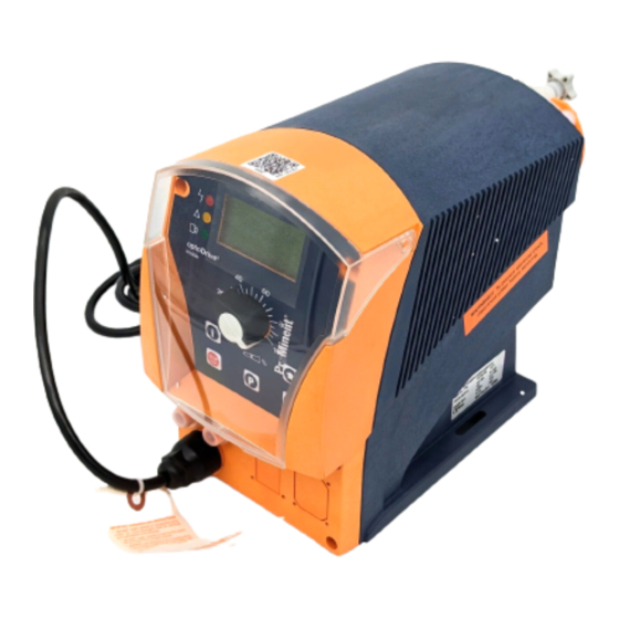
ProMinent delta General Operating Instructions

ProMinent delta General Operating Instructions

Solenoid metering pumps

Advertisement

General Operating Instructions
ProMinent
®
gamma/ L
Two sets of operating instructions are required for the safe, correct and proper operation of the metering pumps: the
product-specific operating instructions (for instance for beta) and the "General Operating Instructions for ProMinent
noid Metering Pumps".
Both sets of operating instructions are only valid when read together.
Please carefully read these operating instructions before use! · Do not discard!
The operator shall be liable for any damage caused by installation or operating errors!
Part no. 987057
Solenoid Metering Pumps
Technical changes reserved.
Original Operating Instructions (2006/42/EC)
delta
®
Beta
®
®
Sole‐
BA MAZ 018 08/12 EN

Advertisement

Table of Contents
loading

Summary of Contents for ProMinent delta

  • Page 1 Beta ® Two sets of operating instructions are required for the safe, correct and proper operation of the metering pumps: the product-specific operating instructions (for instance for beta) and the "General Operating Instructions for ProMinent ® Sole‐ noid Metering Pumps".
  • Page 2 ProMinent Dosiertechnik GmbH Im Schuhmachergewann 5-11 69123 Heidelberg Germany Telephone: 06221 842-0 Fax: 06221 842-617 email: info@prominent.com Internet: www.prominent.com 987126, 1, en_GB © 2003...
  • Page 3 Safety information is identified by pictograms - see Safety Chapter. User information Two sets of operating instructions are required for the safe, correct and proper operation of the metering pumps: The product-specific operating instructions and the "General Operating Instructions for ProMinent Sole‐ ® noid Metering Pumps".
  • Page 4: Table Of Contents

    Table of contents Table of contents Safety Chapter................. 5 Assembly..................7 Installation, hydraulic............... 8 3.1 Overview and Information on Accessories......8 3.2 Standard installation.............. 10 3.3 Information on the suction-side installation......11 3.4 Information on the discharge-side installation....... 13 3.5 How not to install..............14 3.6 Special installation instructions..........
  • Page 5: Safety Chapter

    Safety Chapter Safety Chapter Explanation of the safety information The following signal words are used in these operating instructions to identify different severities of a hazard: Signal word Meaning WARNING Denotes a possibly hazardous sit‐ uation. If this is disregarded, you are in a life-threatening situation and this can result in serious inju‐...
  • Page 6 Safety Chapter CAUTION! Warning of illegal operation Observe the regulations that apply where the unit is to be installed. NOTICE! Danger from incorrect dosing Should a different liquid end size be fitted, this will change the dosing behaviour of the pump. –...
  • Page 7: Assembly

    Assembly Assembly WARNING! Risk of electric shock If water or other electrically conducting liquids penetrate into the drive housing, an electric shock may occur. – Position the pump so that drive housing cannot be flooded. CAUTION! Danger from incorrectly operated or inadequately maintained pumps Danger can arise from a poorly accessible pump due to incorrect operation and poor maintenance.
  • Page 8: Installation, Hydraulic

    Installation, hydraulic Installation, hydraulic 3.1 Overview and Information on Accessories In addition to a correctly selected metering pump, individually combined hydraulic and electrical accessories are needed for the perfect operation of metering systems. A number of accessories are shown on the following pages, which are not always needed but provide an overview of the pos‐...
  • Page 9 Installation, hydraulic System components Function Metering pump* A Metering a defined volume in liquid into Perfect adaptation to metering tasks is a system. Control: manual or automatic possible thanks to the variably adjustable (external signal) metering volume and external control options.
  • Page 10: Standard Installation

    Installation, hydraulic System components Function Vacuum cylinder Smooths out pulsation in the pipe (suc‐ ... to reduce pressure losses with longer tion side), generates a low-pulsation suction lines. flow Priming aid ... as a priming aid together with a vacuum pump.
  • Page 11: Information On The Suction-Side Installation

    Installation, hydraulic Legend for all hydraulic diagrams Icon Explanation Icon Explanation Metering pump Foot valve with filter meshes Injection valve Filter insert Settable back pressure Hopper with float valve valve (also used as a relief valve) Multifunctional valve Level switch Shut-off valve Manometer Solenoid valve...
  • Page 12 Installation, hydraulic With dirt or impurities in the feed chemical, fit a filter insert (mesh width 100–400 μm depending on the feed chemical and type of metering pump) for example. Always connect the suction line somewhat above the tank base or any sediment accumulated.
  • Page 13: Information On The Discharge-Side Installation

    Fig. 12 Avoid exceeding maximum permissible operating pressure A relief valve with a return into the storage tank is useful as overload protection for the discharge line, for example install a ProMinent ® mul‐ tifunctional valve. Dampen pressure peaks with a metering stroke with long discharge lines with a pulsation dampener or increase the pipe cross-section.
  • Page 14: How Not To Install

    Installation, hydraulic 3.5 How not to install Fault description Cause Remedy Ä ‘With The suction line cannot be A pocket of air (arrow) is in the Prevent the air pocket or install as shown in high suction-side pressure 1’ on page 15 . bled.
  • Page 15: Special Installation Instructions

    Installation, hydraulic Fig. 19 3.6 Special installation instructions With high suction-side pressure 1 Position the end of the discharge line higher than the fluid level in the storage tank to avoid overstraining. P_MAZ_0013_SW Fig. 20 With high suction-side pressure 2 Position the outlet of the discharge line higher than the fluid level in the storage tank to avoid overstraining.
  • Page 16 Installation, hydraulic With fluctuating suction-side pressure 2 If the system is primed from a high feed level with fluctuating pressure, use a hopper with a float valve to ensure a regular discharge flow. P_MAZ_0010_SW Fig. 24 With negative pressure in the main line When metering into a main line, in which there is negative pressure, install a multifunctional valve, a back pressure valve (DHV-RM) or an injection valve in the discharge line to ensure that the feed chemical is...
  • Page 17: Start Up

    – Take into account the resistance of the material con‐ tacted by the chemical when selecting the feed chemical - refer to the ProMinent ® resistance list in the product www.prominent.com . equipment catalogue or at Reliable metering cannot be guaranteed after the –...
  • Page 18 Start up Start up the relief valve in the system. Start up the system. Ä ‘Setting the precise dosage’ Set the precise dosage - on page 19 . After 24 operating hours: Tighten the screws on the dosing head - see below for starting torque.
  • Page 19 Start up Switch off the metering pump. ð The metering pump is ready for operation. Setting the precise dosage Stroke length and stroke rate Select as large a stroke length as possible with gaseous – feed chemicals. Select as high a stroke rate as possible for good mixing. –...
  • Page 20: Accessories

    The use of untested third party parts can result in damage to personnel and material damage. – Only fit parts to dosing pumps, which have been tested and recommended by ProMinent. Level switch 2-stage, with 2 m connecting cable. Fault indicating relay for reporting faults.
  • Page 21: Warranty Claim

    Warranty claim Warranty claim Please copy and return with the pump! If the meter ing pump fail s within the warranty perio d, please return it to us in a c leaned sta te with a fu lly co mpleted warranty cl aim.
  • Page 22: Installation Details

    Installation details Installation details Ins tall ati on details Cust omer: Project no.: Date: Sketch enclosed: Pump Type: Pump capacity Strokes/min Stroke rate Stroke length Valve spring pressure, suction-side Valve spring pressure, discharge-side Medi um Description/Concentration - / % Proportion of solids/Grain size % / mm Solids material/Degree of hardness - / (Mohs scale)
  • Page 23: Decontamination Declaration

    Decontamination declaration Decontamination declaration...
  • Page 24: Index

    Index Index Assembly................. 7 Information in the event of an emergency....... 6 Avoid deposits in the liquid end........16 Information on the discharge-side installation....13 Installation, hydraulic............8 Components..............9 Installation details ............22 Decontamination declaration......... 23 Negative pressure in the main line........ 16 Discharge-side installation..........

This manual is also suitable for:

Gamma/ lBeta

Table of Contents