Table of Contents
Advertisement
Quick Links
Operating instructions
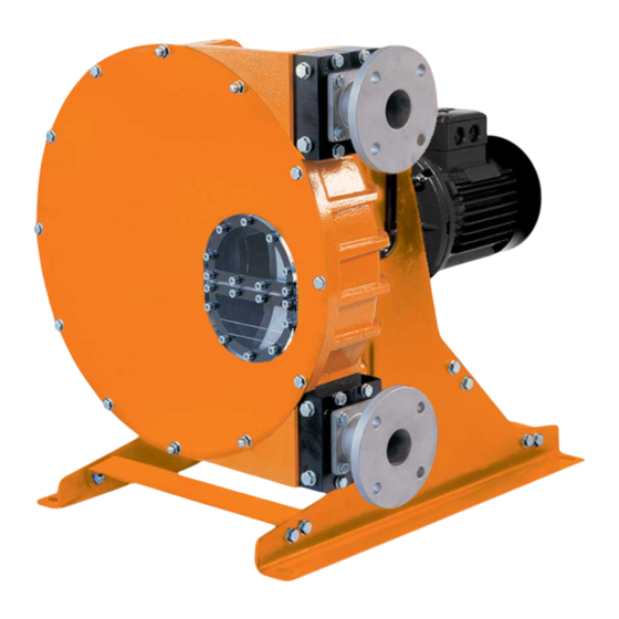
DULCOflex DFDa
Peristaltic Pump
EN
A0381
Please carefully read these operating instructions before use. · Do not discard.
The operator shall be liable for any damage caused by installation or operating errors.
The latest version of the operating instructions are available on our homepage.
Part no. 986226
Original Operating Instructions (2006/42/EC)
Version: BA DX 039 10/21 EN
Advertisement
Table of Contents
Troubleshooting

Related Manuals for ProMinent DULCOflex DFDa


Summary of Contents for ProMinent DULCOflex DFDa
- Page 1 Operating instructions DULCOflex DFDa Peristaltic Pump A0381 Please carefully read these operating instructions before use. · Do not discard. The operator shall be liable for any damage caused by installation or operating errors. The latest version of the operating instructions are available on our homepage.
- Page 2 Supplemental directives General non-discriminatory approach In order to make it easier to read, this document uses the male form in grammatical structures but with an implied neutral sense. It is aimed equally at both men and women. We kindly ask female readers for their understanding in this simplification of the text.
-
Page 3: Table Of Contents
Table of contents Table of contents Introduction................4 1.1 Explanation of the safety information......4 1.2 Users' qualifications............5 1.3 Identity Code for DULCO ® flex DFDa 025..... 7 1.4 Identity Code for DULCO ® flex DFDa 032..... 9 1.5 Identity Code for DULCO ®... -
Page 4: Introduction
Introduction Introduction These operating instructions provide information on the technical data and functions of the DULCO ® flex peristaltic pump from the DFDa product range. 1.1 Explanation of the safety information Introduction These operating instructions provide information on the technical data and functions of the product. -
Page 5: Users' Qualifications
A trained user is a person who fulfils the requirements made of an instructed person and who has also received additional training specific to the system from ProMinent or another authorised distribution partner. Trained qualified per‐ A qualified employee is deemed to be a person who is able to assess the... - Page 6 Customer Service depart‐ Customer Service department refers to service technicians, who have ment received proven training and have been authorised by ProMinent to work on the system. Note for the system operator The pertinent accident prevention regulations, as...
-
Page 7: Identity Code For Dulco
Introduction 1.3 Identity Code for DULCO ® flex DFDa 025 Identity code DFDa DULCO ® flex DFDa 025 Type DFDa 025, 0.3 l/revolution Power end/drive Pump without power end/drive Reduction gear system / 3 x 230 / 400 VAC 0.55 kW, 18 rpm, 324 l/h, 15 bar 0.75 kW, 28 rpm, 504 l/h, 15 bar 0.75 kW, 39 rpm, 702 l/h, 10 bar 0.75 kW, 45 rpm, 810 l/h, 5 bar... - Page 8 Introduction Identity code DFDa DULCO flex DFDa 025 ® Rotor Rotor with 2 shoes Batch control No batch control Special version Standard Housing, Halar ® coated Vacuum system none with vacuum system Approvals CE mark...
-
Page 9: Identity Code For Dulco
Introduction 1.4 Identity Code for DULCO ® flex DFDa 032 Identity code DFDa DULCO ® flex DFDa 032 Type DFDa 032, 0.625 l/revolution Power end/drive Pump without power end/drive Reduction gear system / 3 x 230 / 400 VAC 0.75 kW, 21 rpm, 787 l/h, 10 bar 1.10 kW, 21 rpm, 787 l/h, 15 bar 1.10 kW, 30 rpm, 1125 l/h, 10 bar 1.10 kW, 38 rpm, 1425 l/h, 10 bar... - Page 10 Introduction Identity code DFDa DULCO flex DFDa 032 ® with leakage sensor + relay output Rotor Rotor with 2 shoes Batch control No batch control Special version Standard Housing, Halar ® coated Vacuum system none with vacuum system Approvals CE mark...
-
Page 11: Flex Dfda 040
Introduction 1.5 Identity Code for DULCO ® flex DFDa 040 Identity code DFDa DULCO ® flex DFDa 040 Type 040 DFDa 040, 1.33 l/revolution Power end/drive Pump without power end/drive Reduction gear system / 3 x 230 / 400 VAC 1.10 kW, 21 rpm, 1676 l/h, 10 bar 1.10 kW, 26 rpm, 2075 l/h, 7.5 bar 1.50 kW, 21 rpm, 1676 l/h, 10 bar... - Page 12 Introduction Identity code DFDa DULCO flex DFDa 040 ® Leakage sensor without leakage sensor with leakage sensor with leakage sensor + relay output Rotor Rotor with 2 shoes Batch control No batch control Special version Standard Housing, Halar ® coated Vacuum system none with vacuum system...
-
Page 13: Identity Code For Dulco
Introduction 1.6 Identity Code for DULCO ® flex DFDa 060 Identity code DFDa DULCO ® flex DFDa 060 Type DFDa 060, 2.9 l/revolution Power end/drive Pump without power end/drive Reduction gear system / 3 x 230 / 400 VAC D11 2.20 kW, 22 rpm, 3.8 m /h, 5 bar D12 3.00 kW, 26 rpm, 4.5 m /h, 5 bar... - Page 14 Introduction Identity code DFDa DULCO flex DFDa 060 ® with leakage sensor with leakage sensor + relay output Rotor Rotor with 2 shoes Batch control No batch control Special version Standard Housing, Halar ® coated Vacuum system none with vacuum system Approvals CE mark...
-
Page 15: Flex Dfda 070
Introduction 1.7 Identity Code for DULCO ® flex DFDa 070 Identity code DFDa DULCO ® flex DFDa 070 Type 070 DFDa 070, 6.70 l/revolution Power end/drive Pump without power end/drive Reduction gear system / 3 x 230 / 400 VAC 3.00 kW, 13.5 rpm, 5.4 m /h, 5 bar 4.0 kW, 18 rpm, 7.2 m... - Page 16 Introduction Identity code DFDa DULCO flex DFDa 070 ® Rotor Rotor with 2 shoes Batch control No batch control Special version Standard Housing, Halar ® coated Vacuum system none with vacuum system Approvals CE mark...
-
Page 17: Flex Dfda 080
Introduction 1.8 Identity Code for DULCO ® flex DFDa 080 Identity code DFDa DULCO ® flex DFDa 080 Type 080 DFDa 080, 11.70 l/revolution Power end/drive Pump without power end/drive Reduction gear system / 3 x 230 / 400 VAC 4.00 kW, 12.5 rpm, 8.7 m /h, 5 bar 5.5 kW, 17.6 rpm, 12.3 m... - Page 18 Introduction Identity code DFDa DULCO flex DFDa 080 ® Vacuum system none with vacuum system Approvals CE mark...
-
Page 19: Identity Code For Dulco
Introduction 1.9 Identity Code for DULCO ® flex DFDa 100 Identity code DFDa DULCO ® flex DFDa 100 Type DFDa 100, 20.0 l/revolution Power end/drive Pump without power end/drive Reduction gear system / 3 x 230 / 400 VAC 7.5 kW, 12.0 rpm, 14.4 m /h, 5 bar 11.0 kW, 18.0 rpm, 21.6 m /h, 5 bar... - Page 20 Introduction Identity code DFDa DULCO flex DFDa 100 ® Vacuum system none with vacuum system Approvals CE mark...
-
Page 21: Safety And Responsibility
Safety and responsibility Safety and responsibility 2.1 General safety information WARNING! Live parts Possible consequence: Fatal or very serious inju‐ ries – Measure: The device must be disconnected from the power supply before it is opened – Isolate damaged, faulty or manipulated devices from the mains in order to de-energise. - Page 22 Safety and responsibility WARNING! Correct and proper use Possible consequence: Fatal or very serious inju‐ ries – The unit is not intended to convey or regulate gaseous or solid media – Do not exceed the rated pressure, speed or temperature for the pump –...
- Page 23 Safety and responsibility CAUTION! Environmental influences Possible consequence: Material damage right through to destruction of the unit – The device is not suitable for outdoor operation – Take suitable measures to protect the device from environmental influences such as: – UV rays –...
-
Page 24: Functional Description
Functional description Functional description Brief functional description The package contents supplied with the DULCO flex DFDa is ® selectable via the identcode. The DULCO flex DFDa is a displacement pump. The feed chem‐ ® ical is transported by the rotor squeezing the hose in the direction of flow. -
Page 25: Construction
Functional description 3.2 Construction Main modules: Drive Unit Housing Base frame The pump housing is closed off with a screwed front cover in order to avoid the risk of injury. The motor serves to drive the rotor. Two shoes at the ends of the rotor serve to press the pump hose against the pump housing. -
Page 26: Transport, Storage, Assembly And Installation
Transport, storage, assembly and Installation Transport, storage, assembly and Installation User qualification, transport and storage: trained user, see Ä Chapter 1.2 ‘Users' qualifications’ on page 5 User qualification, installation: trained qualified personnel, see Ä Chapter 1.2 ‘Users' qualifications’ on page 5 User qualification, electrical installation: Electrical technician, Ä... -
Page 27: Storage
Transport, storage, assembly and Installation A0402 Fig. 2: Lifting the DFDa 025 / 032 / 040 Lifting lug The lifting lugs (1) on the pump housing are used to life the DFDa 025 / 032 / 040. A0403 Fig. 3: Lifting the DFDa 060 / 070 / 080 / 100 Appropriate lifting equipment is used to lift the DFDa 060 / 070 / 080 / 100, as shown in Fig. -
Page 28: Assembly
Transport, storage, assembly and Installation 4.3 Assembly CAUTION! Possible consequence: Slight or minor injuries. Material damage. Carry out assembly work before commencing the electrical installation. Observe the permissible ambient conditions. 4.3.1 Ambient conditions NOTICE! Ambient conditions Possible consequence: Property damage and increased wear and tear Assembly is to be carried out in the following order. -
Page 29: Alignment Of The Suction Side
Transport, storage, assembly and Installation 4.3.2 Alignment of the suction side The pump is to be positioned as near as possible to the liquid con‐ tainer, so that the suction side is kept as short and straight as pos‐ sible. The suction line must be absolutely airtight and made of a suitable material, so that it is not squeezed together under vacuum. - Page 30 Transport, storage, assembly and Installation P_DX_0021_SW Fig. 5: Squeezing the hose Normal shape of hose Excessive squeezing (increased wear and tear on the pump and hose) Perfect squeezing Insufficient squeezing (medium backflowing in the cavity will destroy the hose within a short period of time) The spacer plates are factory-fitted.
- Page 31 Transport, storage, assembly and Installation Tab. 4: DFDa 032 / Number of spacer plates: 0 ... 19 20 ... 39 40 ... 59 60 ... 79 80 ... 99 5.0 * 10.0 12.5 15.0 * Delivered state Tab. 5: DFDa 040 / Number of spacer plates: 0 ...
- Page 32 Transport, storage, assembly and Installation Tab. 7: DFDa 070 / Number of spacer plates: 0 ... 19 20 ... 39 40 ... 59 60 ... 79 80 ... 99 5.0* 10.0 12.5 15.0 * Delivered state Tab. 8: DFDa 080 / Number of spacer plates: 0 ...
-
Page 33: Performance Curves
Transport, storage, assembly and Installation 4.3.5 Performance curves NOTICE! Maximum pressure under continuous operation The lines indicate the limit for maximum pressure under continuous operation Fig. 6: DFDa 025 Fig. 7: DFDa 032... - Page 34 Transport, storage, assembly and Installation Fig. 8: DFDa 040 Fig. 9: DFDa 060...
- Page 35 Transport, storage, assembly and Installation Fig. 10: DFDa 070 A2022 Fig. 11: DFDa 080...
-
Page 36: Commissioning
Transport, storage, assembly and Installation Fig. 12: DFDa 100 4.3.6 Commissioning Ä Chapter User qualification, commissioning: trained user, see 1.2 ‘Users' qualifications’ on page 5 4.3.6.1 Testing prior to commissioning the pump The following tests are to be carried out: Ensure that the pump has not been damaged during transpor‐... - Page 37 Transport, storage, assembly and Installation Check the operating instructions in order to ensure that the flow values, pressures and power consumption of the motor do not exceed the rated values Install a pressure relief valve in the pressure line in order to protect the pump in the event that a valve is unintentionally closed off or the line is blocked in another way.
-
Page 38: Operating The Dfda
Operating the DFDa Operating the DFDa User qualification, operation: instructed persons, see Ä Chapter 1.2 ‘Users' qualifications’ on page 5 The peristaltic pump is to be fully integrated into the customer's designated plant and is then controlled by this plant. It is not pos‐ sible to operate the pump directly. -
Page 39: Maintenance, Repair, Troubleshooting, Disposal And Spare Parts
Maintenance, repair, troubleshooting, disposal and spare parts Maintenance, repair, troubleshooting, disposal and spare parts User qualification, maintenance and disposal: instructed per‐ Ä Chapter 1.2 ‘Users' qualifications’ on page 5 sonnel, see User qualification, repair and troubleshooting: trained user, see Ä Chapter 1.2 ‘Users' qualifications’ on page 5 6.1 Maintenance CAUTION! Disconnect the pump from the mains... - Page 40 Maintenance, repair, troubleshooting, disposal and spare parts Fig. 13: Overview of bearing flange Bearing flange Flange sleeve Pump hose Pump housing Clamping ring O-ring external O-ring internal Flange screws (4 pieces) Exchanging the pump hoses - installa‐ Remove the front cover and clean the inner surface of the tion pump housing Check the shoes.
-
Page 41: Troubleshooting
Maintenance, repair, troubleshooting, disposal and spare parts Now carefully screw the bearing flange with the four screws onto the pump housing. In doing so, ensure that the flange sleeve is not damaged. If necessary, knock the flange sleeve in with a plastic-faced hammer Now fasten the bearing flange and clamping ring on the suc‐... -
Page 42: Disposal Of Used Parts
Decontaminate the unit before returning it for repair. To do so, remove all traces of hazardous substances. Refer to the Material Safety Data Sheet for your feed chemical. A current Declaration of Decontamination is available to download on the ProMinent website. -
Page 43: Spare Parts
Maintenance, repair, troubleshooting, disposal and spare parts 6.5 Spare parts A0405 Fig. 14: Exploded view of spare parts for DFDa 025 DFDa 025 see Fig. 14 Item Description Quantity Reference Part number Pump housing 100.01.01 Housing, ball bearing 100.01.03 Rotor shaft 100.01.14 Rotor 100.01.16... - Page 44 Maintenance, repair, troubleshooting, disposal and spare parts DFDa 025 see Fig. 14 Item Description Quantity Reference Part number Base plate, right 100.01.25 Base plate, right, stainless steel 100.01.35 Base plate, centre 100.01.26 Base plate, centre, stainless steel 100.01.36 Stud bolts 102.00.14 Power end/drive Ball bearing...
- Page 45 Maintenance, repair, troubleshooting, disposal and spare parts A0406 Fig. 15: Exploded view of spare parts for DFDa 032 DFDa 032 see Fig. 15 Item Description Quantity Reference Part number Pump housing 104.01.01 Housing, ball bearing 104.01.03 Rotor shaft 104.01.14 Rotor 104.01.16 Shoes 104.01.17...
- Page 46 Maintenance, repair, troubleshooting, disposal and spare parts DFDa 032 see Fig. 15 Item Description Quantity Reference Part number Base plate, left 106.00.24 Base plate, right 106.00.25 Base plate, centre 106.00.26 Stud bolts 106.00.27 Power end/drive Ball bearing 106.00.28 Ball bearing 106.00.29 Safety collar 106.00.31...
- Page 47 Maintenance, repair, troubleshooting, disposal and spare parts A0407 Fig. 16: Exploded view of spare parts for DFDa 040 DFDa 040 see Fig. 16 Item Description Quantity Reference Part number Pump housing 109.00.01 Housing, ball bearing 108.00.02 Rotor shaft 108.00.03 Rotor 109.00.02 Shoes 109.00.03...
- Page 48 Maintenance, repair, troubleshooting, disposal and spare parts DFDa 040 see Fig. 16 Item Description Quantity Reference Part number Pump hose, NBR 108.00.22 1037201 Pump hose, EPDM 108.00.24 1037202 104.01.23 Base plate, left 108.00.26 Base plate, left, stainless steel 108.00.36 Base plate, right 108.00.27 Base plate, right, stainless steel 108.00.37...
- Page 49 Maintenance, repair, troubleshooting, disposal and spare parts A0408 Fig. 17: Exploded view of spare parts for DFDa 060 DFDa 060 see Fig. 17 Item Description Quantity Reference Part number Pump housing 111.01.01 Spacer plate 111.00.02 Housing, ball bearing 111.00.03 Rotor shaft 111.00.04 Rotor 111.00.05...
- Page 50 Maintenance, repair, troubleshooting, disposal and spare parts DFDa 060 see Fig. 17 Item Description Quantity Reference Part number Connecting flange, ANSI, VA 110.01.41 Connecting flange, DIN, PVDF/PTFE 110.01.72 Connecting flange, ANSI, PVDF/PTFE 110.01.65 Connecting flange, DIN, PP 110.01.64 Connecting flange, ANSI, PP 110.01.63 Pump hose, NR 111.00.18...
- Page 51 Maintenance, repair, troubleshooting, disposal and spare parts A0409 Fig. 18: Exploded view of spare parts for DFDa 070 DFDa 070 see Fig. 18 Item Description Quantity Reference Part number Pump housing 112.00.01 Ball bearing housing 111.00.03 Rotor shaft 111.00.04 Rotor 114.00.01 Shoes 114.00.02...
- Page 52 Maintenance, repair, troubleshooting, disposal and spare parts DFDa 070 see Fig. 18 Item Description Quantity Reference Part number Connecting flange, DIN 11851, NW 65 112.00.13 112.00.43 Connecting flange, TRI-CLAMP ® Pump hose, NR 112.00.18 1037213 Pump hose, NBR 112.00.20 1037214 Pump hose, EPDM 112.00.22 1037215...
- Page 53 Maintenance, repair, troubleshooting, disposal and spare parts 30 1 26 11 24 23 A2025 Fig. 19: Exploded view of spare parts for DFDa 080 DFDa 080 see Fig. 19 Pos. Description Quantity Reference Part number Pump housing 118.00.01 Ball bearing housing 119.00.02 Rotor shaft 119.00.03...
- Page 54 Maintenance, repair, troubleshooting, disposal and spare parts DFDa 080 see Fig. 19 Pos. Description Quantity Reference Part number Connecting flange, DN-80, VA, DIN 11851 118.00.32 Connecting flange, DN-80, VA, DIN 118.00.05 Pump hose, EPDM 118.00.14 1041679 Pump hose, NBR 118.00.13 1041678 Pump hose, NR 118.00.12...
- Page 55 Maintenance, repair, troubleshooting, disposal and spare parts 30 1 26 11 24 23 A2024 Fig. 20: Exploded view of spare parts for DFDa 100 DFDa 100 see Fig. 20 Pos. Description Quantity Refer‐ Part number ence Pump housing 119.00.01 Ball bearing housing 119.00.02 Rotor shaft 119.00.03...
- Page 56 Maintenance, repair, troubleshooting, disposal and spare parts DFDa 100 see Fig. 20 Pos. Description Quantity Refer‐ Part number ence Connecting flange, DN-100, PVDF, DIN 119.00.15 Connecting flange, DN-100, VA, DIN 11851 119.00.17 Connecting flange, DN-100, VA, DIN 119.00.11 Pump hose, EPDM 119.00.21 1037249 Pump hose, NBR 119.00.20 1037248...
-
Page 57: Dfda Technical Data
DFDa Technical Data DFDa Technical Data Type Feed rate P max. Pump Rollers/ Hose Solids Weight Con‐ capacity nector DFDa in l/revo‐ in bar Shoes interior max. without lution at max. drive ⌀ in mm ⌀ in mm pressure in kg in l/h Shoes 0.625... -
Page 58: Dimensions Dfda 025
DFDa Technical Data 7.1 Dimensions DFDa 025 1 1 4 4 8 8 5 5 1 1 1 1 5 5 A0390 Fig. 21: Dimensions DFDa 025 A 127.5 mm H 305 mm B ✱ 160 mm C ✱ 100 mm D 60 mm K 262 mm E 425 mm... -
Page 59: Dimensions Dfda 032
DFDa Technical Data 7.2 Dimensions DFDa 032 Fig. 22: Dimensions DFDa 032 A 135 mm H 385 mm B ✱ 170 mm C ✱ 130 mm K 330 mm E 613 mm 345 mm ✱ Dependent on selected drive G 552 mm... -
Page 60: Dimensions Dfda 040
DFDa Technical Data 7.3 Dimensions DFDa 040 A0392 Fig. 23: Dimensions DFDa 040 A 151 mm H 456 mm B ✱ 200 mm C ✱ 159 mm D 79 mm K 412 mm E 645 mm 115 mm 415 mm ✱... -
Page 61: Dimensions Dfda 060
DFDa Technical Data 7.4 Dimensions DFDa 060 A0393 Fig. 24: Dimensions DFDa 060 A 215 mm H 500 mm B ✱ 25 mm C ✱ 210 mm D 111 mm K 510 mm E 805 mm 25 mm 740 mm ✱... -
Page 62: Dimensions Dfda 070
DFDa Technical Data 7.5 Dimensions DFDa 070 A0394 Fig. 25: Dimensions DFDa 070 A 215 mm H 790 mm B ✱ 40 mm C ✱ 240 mm D 250 mm K 784 mm E 1124 mm 40 mm 1065 mm ✱... -
Page 63: Dimensions Dfda 080
DFDa Technical Data 7.6 Dimensions DFDa 080 DIN FLANGE DIN FLANGE DN-80 DN-80 A2023 Fig. 26: Dimensions DFDa 080 A 1200 mm E 850 mm B 1093 mm 17.5 mm C Dependent on selected drive G 160 mm D 205 mm H 200 mm... -
Page 64: Dimensions Dfda 100
DFDa Technical Data 7.7 Dimensions DFDa 100 A0389 Fig. 27: Dimensions DFDa 100 A 1,500 mm 17.5 mm B 1,360 mm G 180 mm C ✱ H 220 mm D 237 mm ✱ Dependent on selected drive E 1,000 mm... -
Page 65: Technical Appendices For The Dfda
In accordance with DIRECTIVE 2006/42/EC OF THE EUROPEAN PARLIAMENT AND OF THE COUNCIL, Appendix I, BASIC HEALTH AND SAFETY REQUIREMENTS, section 1.7.4.2. C. ProMinent GmbH Im Schuhmachergewann 5 - 11 D - 69123 Heidelberg, hereby declare that the product specified in the following, complies... -
Page 66: Index
Index Index Pump lubricant ......37 Action, step by step ......2 Applied harmonised standards . - Page 68 ProMinent GmbH Im Schuhmachergewann 5 - 11 69123 Heidelberg Telephone: +49 6221 842-0 Fax: +49 6221 842-419 Email: info@prominent.com Internet: www.prominent.com 986226, 5, en_GB © 2021...
Need help?
Do you have a question about the DULCOflex DFDa and is the answer not in the manual?
Questions and answers