Table of Contents
Advertisement
Quick Links
Advertisement
Table of Contents

Related Manuals for Keysight N1913B EPM Series


Summary of Contents for Keysight N1913B EPM Series
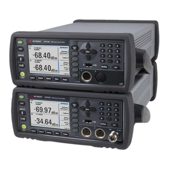
- Page 1 EPM Series Power Meters N1913B EPM Series N1914B EPM Series SERVICE GUIDE...
- Page 2 FAR 27.401 or DFAR could result in personal injury or death. 227.7103-5 (c), as applicable in any Do not proceed beyond a WARNING technical data. notice until the indicated conditions are fully understood and met. Keysight N1913B/N1914B EPM Series Power Meters Service Guide...
-
Page 3: Certification
Certification Keysight Technologies certifies that this product met its published specifications at the time of shipment from the factory. Keysight Technologies further certifies that its calibration measurements are traceable to the United States National Institute of Standard and Technology, to the extent allowed by the Institute’s calibration facility, and to the calibration facilities of other International Standard Organization members. -
Page 4: Equipment Operation
(for example, normal blow, time delay, etc.). The use of other fuses or material is prohibited. Keysight N1913B/N1914B EPM Series Power Meters Service Guide... -
Page 5: Safety Considerations
REMOVE POWER and do not use the product until safe operation can be verified by service-trained personnel. If necessary, return the product to a Keysight Technologies Sales and Service Office for service and repair to ensure the safety features are maintained. - Page 6 Return the product to a Keysight Technologies Sales and Service Office for service and repair to ensure the safety features are maintained. – Use a Keysight supplied power cord that has the same electrical rating. CLEAN WITH SLIGHTLY DAMPENED CLOTH CAUTION Clean the outside of the instrument with a soft, lint-free, slightly dampened cloth.
-
Page 7: Safety Symbols
The N1913B/N1914B EPM Series power meters are designed to comply with the following safety and EMC (Electromagnetic Compatibility) requirements: Safety compliance – Low Voltage Directive 2014/35/EU EMC compliance – EMC Directive 2014/30/EU Keysight N1913B/N1914B EPM Series Power Meters Service Guide... -
Page 8: Regulatory Markings
Forty years is the expected useful life Please refer to www.keysight.com/go/ of the product. takeback to understand your Trade-in options with Keysight in addition to product take back instructions. Keysight N1913B/N1914B EPM Series Power Meters Service Guide... -
Page 9: Sales And Technical Support
Sales and Technical Support To contact Keysight for sales and technical support, refer to the support links on the following Keysight websites: – www.keysight.com/find/epm (product-specific information and support, software and documentation updates) – www.keysight.com/find/assist (worldwide contact information for repair and service) - Page 10 THIS PAGE HAS BEEN INTENTIONALLY LEFT BLANK. Keysight N1913B/N1914B EPM Series Power Meters Service Guide...
-
Page 11: Table Of Contents
..........44 Keysight N1913B/N1914B EPM Series Power Meters Service Guide... - Page 12 ..........66 Keysight N1913B/N1914B EPM Series Power Meters Service Guide...
- Page 13 ........75 Keysight N1913B/N1914B EPM Series Power Meters Service Guide...
- Page 14 ......138 Before Calling Keysight Technologies ......139 Keysight N1913B/N1914B EPM Series Power Meters Service Guide...
- Page 15 .........143 Keysight N1913B/N1914B EPM Series Power Meters Service Guide...
- Page 16 THIS PAGE HAS BEEN INTENTIONALLY LEFT BLANK. Keysight N1913B/N1914B EPM Series Power Meters Service Guide...
- Page 17 ... .123 Figure 6-19 Separate the two halves of the ferrite ... .135 Keysight N1913B/N1914B EPM Series Power Meters Service Guide...
- Page 18 THIS PAGE HAS BEEN INTENTIONALLY LEFT BLANK. Keysight N1913B/N1914B EPM Series Power Meters Service Guide...
- Page 19 ..... .38 Table 1-9 U2000 Series settling time ..... .39 Keysight N1913B/N1914B EPM Series Power Meters Service Guide...
- Page 20 THIS PAGE HAS BEEN INTENTIONALLY LEFT BLANK. Keysight N1913B/N1914B EPM Series Power Meters Service Guide...
-
Page 21: Specifications And Characteristics
Keysight N1913B/N1914B EPM Series Power Meters Service Guide Specifications and Characteristics Introduction Recommended Calibration Interval Power Meter Specifications Power Sensor Specifications Power Meter Supplemental Characteristics Settling Time Measurement Characteristics Rear Panel Inputs and Output Connections 1 mW Power Reference Physical Characteristics This chapter describes the specifications and characteristics of your EPM Series Power Meters. -
Page 22: Introduction
50 input is nominal. These two terms are most widely used when describing a product's 'attributes'. – The second group of characteristic types describes 'statistically' the aggregate performance of the population of products. Keysight N1913B/N1914B EPM Series Power Meters Service Guide... -
Page 23: Recommended Calibration Interval
30 minutes. – The power meter and power sensor are within their recommended calibration periods. – Used in accordance to the information provided in the Keysight N1913B/ N1914B EPM Series Power Meters User's Guide. Recommended Calibration Interval Keysight Technologies recommends a two-year calibration cycle for the N1913B/ N1914B EPM Series Power Meters. -
Page 24: Power Meter Specifications
– 90 dB maximum (Keysight E-Series power sensors) – 50 dB maximum (Keysight 8480 Series power sensors) – 55 dB maximum (Keysight N8480 Series power sensors) – 80 dB maximum (Keysight U2000 Series USB power sensors) Display Units Absolute: Watts (W) or dBm... -
Page 25: Power Sensor Specifications
Zero Set (digital settability of zero): Power sensor dependent (refer to Table 1-1 Table 1-2). For Keysight E-Series power sensors, this specification applies when zeroing is performed with the sensor input disconnected from the POWER REF. [1] Refer to the power sensor linearity specification in your power sensor manual to assess overall system accuracy. - Page 26 ±50 nW Q8486A ±30 pW Q8486D ±200 nW V8486A ±200 nW W8486A ±50 nW 8487A ±20 pW 8487D E4412A ±50 pW E4413A ±50 pW E9300A ±500 pW E9301A ±500 pW E9304A ±500 pW Keysight N1913B/N1914B EPM Series Power Meters Service Guide...
- Page 27 ±63 nW N8486A R with Option CFT ±63 nW N8486A Q with Option CFT ±63 nW N8487A with Option CFT ±63 µW N8481B with Option CFT ±63 µW N8482B with Option CFT Keysight N1913B/N1914B EPM Series Power Meters Service Guide...
-
Page 28: Zero Set (Internal And External) For U2000 Series
N8481H with Option CFT ±6.3 µW N8482H with Option CFT [a] The zero set specifications are tested with Keysight 11730A power sensor cable, 1.5 m (7.5 ft). [b] The zero set specifications are tested at 50 MHz. Table 1-2 Zero set (internal and external) for U2000 Series... -
Page 29: Table 1-1 Table
– U2002A serial prefix MY482/SG482 and above – U2004A serial prefix MY484/SG484 and above For power sensors with earlier prefixes, refer to the Keysight U2000 Series USB Power Sensors Operating and Service Guide. Keysight N1913B/N1914B EPM Series Power Meters Service Guide... -
Page 30: Power Meter Supplemental Characteristics
32 for x2 mode. Use the “Noise Multiplier” for the appropriate mode (normal or x2) and number of averages to determine the total measurement noise value. For example, for a Keysight 8481D power sensor in normal mode with the number of averages set to 4, the measurement noise is equal to: (<45 pW ×... - Page 31 Keysight E9300A <±150 nW <700 nW Keysight E9301A <±150 nW <700 nW Keysight E9304A <±150 nW <700 nW Keysight E9300B <±150 nW <700 nW Keysight E9301B <±1.5 nW <7 nW Keysight E9300H Keysight N1913B/N1914B EPM Series Power Meters Service Guide...
- Page 32 Keysight N8481B with Option CFT <±7 µW <114 µW Keysight N8482B with Option CFT <±0.7 µW <11.4 µW Keysight N8481H with Option CFT <±0.7 µW <11.4 µW Keysight N8482H with Option CFT Keysight N1913B/N1914B EPM Series Power Meters Service Guide...
-
Page 33: U2000 Series Power Sensors Specification
[b] The number of averages at 16 (for normal mode) and 32 (for x2 mode), at a constant temperature, measured over a one minute interval and two standard deviations. For Keysight E-Series power sensors, the measurement noise is measured within the low range. Refer to the relevant power sensor manual for further information. - Page 34 [b] The number of averages at 16 (for normal mode) and 32 (for x2 mode), at a constant temperature, measured over a one minute interval and two standard deviations. For Keysight E-Series power sensors, the measurement noise is measured within the low range. Refer to the relevant power sensor manual for further information.
-
Page 35: Settling Time
10 dB decreasing power step (refer to Table 1-7). Auto-filter, default resolution, 10 dB decreasing power step, normal and x2 speed modes (refer to Figure 1-2 for E441X Series sensors and Figure 1-3 for E9300 Series sensors). Keysight N1913B/N1914B EPM Series Power Meters Service Guide... -
Page 36: Figure 1-2 E441X Series Settling Time With Auto-Filter
130 ms 90 ms +10 dB settling dynamic times range 1.1 s 450 ms +10 dB 6.7 s 3.5 s +10 dB Min dBm Figure 1-2 E441x Series settling time with auto-filter Keysight N1913B/N1914B EPM Series Power Meters Service Guide... -
Page 37: Figure 1-3 E9300 Series Settling Time With Auto-Filter
120 ms 70 ms –30 dBm 400 ms –40 dBm Low power path 6.5 s 3.4 ms –50 dBm 13 s 6.8 s Min dBm Figure 1-3 E9300 Series settling time with auto-filter Keysight N1913B/N1914B EPM Series Power Meters Service Guide... -
Page 38: N8480 Series Settling Time
+10 dB settling dynamic times range 400 ms +10 dB 6.6 s 3.6 s +10 dB 13.5 s 6.6 s +10 dB Min dBm Figure 1-4 N8480 Series settling time with auto-filter Keysight N1913B/N1914B EPM Series Power Meters Service Guide... -
Page 39: U2000 Series Settling Time
20.9 (x2 mode) [a] Manual filter, 10 dB decreasing power step (not across the switching point) [1] When a power step crosses the auto-range switch point of the sensor, add 25 ms. Keysight N1913B/N1914B EPM Series Power Meters Service Guide... - Page 40 30 dBm 10 dBm 42 s 24 s -50 dBm 40 dBm 20 dBm 42 s 24 s Minimum sensor power within a range Figure 1-5 U2000 Series settling time with auto-filter Keysight N1913B/N1914B EPM Series Power Meters Service Guide...
-
Page 41: Measurement Characteristics
– Normal: 20 readings/second – x2: 40 readings/second – Fast : 400 readings/second, for Keysight E-Series power sensors only Maximum measurement speed is obtained using binary output in free run trigger mode. [1] For N1914B, if both channels are used in the fast mode, the measurement speed will be reduced to 200 readings/second for each channel. -
Page 42: Rear Panel Inputs And Output Connections
Input voltage range Automatic voltage selection Fluctuations not exceeding ±10% 50 – 60 Hz (100 to 240 Vac) Input frequency range 400 Hz (100 to 120 Vac) Power requirement 70 VA (maximum) Keysight N1913B/N1914B EPM Series Power Meters Service Guide... -
Page 43: Mw Power Reference
Laboratories (NPL), UK ±1.2% (0 – 55 ºC) Accuracy ±0.4% (25 ±10 ºC) Frequency 50 MHz nominal 1.08 (0 - 55 ºC) 1.05 (typical) Type N (f ), 50 Connector type Keysight N1913B/N1914B EPM Series Power Meters Service Guide... -
Page 44: Physical Characteristics
212.6 mm W x 88.5 mm H x 348.3 mm D (8.5 in x 3.5 in x 13.7 in) Weight 3.60 kg (approximately) N1913B/N1914B weight (net) 8.20 kg (approximately) N1913B/N1914B weight (shipping) Keysight N1913B/N1914B EPM Series Power Meters Service Guide... -
Page 45: Performance Tests
Keysight N1913B/N1914B EPM Series Power Meters Service Guide Performance Tests Introduction Complete Equipment List 1 mW Power Reference Level Test Output Standing Wave Ratio (SWR) Test Zero Set (Average Path) Absolute Accuracy Test (Average Path) Linearity (Average Path) This chapter contains procedures that allows you to test the power meter’s... -
Page 46: Introduction
– This document does not provide a complete breakdown for these tests; it only NOTE gives a brief overview of each, in line with Keysight’s recommendation that the Keysight N7800 Series calibration software should be used at all times. – Performance testing is limited to the measurement and verification of warranted specifications. -
Page 47: Complete Equipment List
Amplitude range: –30 dBm to +20 dBm SWR: 1.1 at 50 MHz Power Sensor Frequency: 50 MHz E4412A Amplitude range: –70 dBm to +20 dBm SWR: 1.06 maximum Attenuator 20 dB Fixed Attenuator N-type (m,f) 8491B (Option 020) Keysight N1913B/N1914B EPM Series Power Meters Service Guide... - Page 48 Cable Assy-Coaxial RG/223 cable 50-Ohm 8120-1839 straight BNC male to straight BNC 24-in LG Calibration Test Cable 11730A required for N1913B and N1914B Sensor Cable 85032B N-Type Calibration Kit 85032B Assorted accessories (cables and adapters) required Keysight N1913B/N1914B EPM Series Power Meters Service Guide...
-
Page 49: Mw Power Reference Level Test
1 mW power reference level test setup connection diagram For rear panel options, the connections will differ from the illustration shown NOTE here. Refer to the connector identification markings on the rear panel for further details. Keysight N1913B/N1914B EPM Series Power Meters Service Guide... -
Page 50: Test Method
DUT. – An adjustment is available for this test if it fails (see Chapter 3, "Adjustments"). Keysight N1913B/N1914B EPM Series Power Meters Service Guide... -
Page 51: Output Standing Wave Ratio (Swr) Test
– 1 unit of 11667A, 1 unit of 8481D, and the 30 dB pad combine to create the ‘Calibration System’ – 1 unit of 11667A, 1 unit of 8481D, and the 20 dB pad combine to create the ‘Measurement System’ Keysight N1913B/N1914B EPM Series Power Meters Service Guide... -
Page 52: Figure 2-2 System Calibration Connection Diagram
Output SWR test setup-open connection diagram EPM SERIES POWER METER POWER METER Ch A 20 dB ATTENUATOR Load Port N-TYPE POWER SENSOR MALE LOAD Figure 2-4 Output SWR test setup-load connection diagram Keysight N1913B/N1914B EPM Series Power Meters Service Guide... -
Page 53: Test Method
– This test cannot be performed manually, due to the complexity of the NOTE equipment calibration procedure, and the complexity of the measurement algorithm. – No adjustment is available for this test if it fails (see Chapter 5, "Troubleshooting Guide"). Keysight N1913B/N1914B EPM Series Power Meters Service Guide... -
Page 54: Zero Set (Average Path)
This test can be performed manually via the commands: NOTE SERV:BIST:CW[1|2]:ZSET SERV:BIST:CW[1|2]:ZSET:NUM? (Refer to the N1913B/N1914B EPM Series Power Meters Programming Guide for further details on the use of these commands) Keysight N1913B/N1914B EPM Series Power Meters Service Guide... -
Page 55: Absolute Accuracy Test (Average Path)
– 1 unit of 11730A power sensor cable – 2 units of 10503A BNC cable – 1 unit of BNC T-joint connector (BNC female, male, female) – 1 unit of BNC (female) to dual banana connector Keysight N1913B/N1914B EPM Series Power Meters Service Guide... -
Page 56: Test Method
Figure 2-5 Absolute accuracy test setup The procedure details the key presses required on the Keysight N1913B Product NOTE name sentence style. For the Keysight N1914B Product name sentence style, the equivalent key presses should be performed on both channels. - Page 57 When switching the range calibrator to STANDBY, allow enough time for the NOTE range calibrator to settle to its zero value before attempting to zero the Keysight N1913B/N1914B Product name sentence style. This settling would appear on the Keysight N1913B/N1914B Product name sentence style display as downward drift.
- Page 58 3.66700 V 10 V ±0.5% 17 dBm 4.65200 V 10 V ±0.5% 18 dBm 5.91500 V 10 V ±0.5% 19 dBm 7.53000 V 10 V ±0.5% 20 dBm 9.62300 V 10 V ±0.5% Keysight N1913B/N1914B EPM Series Power Meters Service Guide...
-
Page 59: Linearity (Average Path)
0. This test can be performed manually via the commands: NOTE SERV:BIST:CW[1|2]:LIN SERV:BIST:CW[1|2]:LIN:PERR? (Refer to the N1913B/N1914B EPM Series Power Meters Programming Guide for further details on the use of these commands) Keysight N1913B/N1914B EPM Series Power Meters Service Guide... - Page 60 Performance Tests THIS PAGE HAS BEEN INTENTIONALLY LEFT BLANK. Keysight N1913B/N1914B EPM Series Power Meters Service Guide...
-
Page 61: Adjustments
Keysight N1913B/N1914B EPM Series Power Meters Service Guide Adjustments Introduction Power Reference Level Adjustment This chapter contains checks and adjustments that ensure proper performance of the power meter. -
Page 62: Introduction
Adjustment of the coarse and fine settings can only be carried out via remote commands. Adjustment can be carried out without having to remove the outer covers from the DUT. Keysight N1913B/N1914B EPM Series Power Meters Service Guide... -
Page 63: Power Reference Level Adjustment
SERV:CAL:ADJ:COUR? SERV:CAL:ADJ:FINE <value> SERV:CAL:ADJ:FINE? (Refer to the Keysight N1913B/N1914B EPM Series Power Meters Programming Guide for further details on the use of these commands.) – COARSE and FINE values are valid in the range of 0 to 1023 – If adjustment is not possible, then a fault may be present in the DUT (see Chapter 5, "Troubleshooting... - Page 64 Adjustments THIS PAGE HAS BEEN INTENTIONALLY LEFT BLANK. Keysight N1913B/N1914B EPM Series Power Meters Service Guide...
-
Page 65: Theory Of Operation
Keysight N1913B/N1914B EPM Series Power Meters Service Guide Theory of Operation Carrier Board Main Board Assembly Calibrator Assembly Front Panel Assembly PSU Assembly This chapter describes how each of the power meter’s individual assemblies operate. -
Page 66: Carrier Board
– Control and data lines [from main board and front panel] – LAN/USB communications [from external equipment] – GPIB communications [from external equipment, via main board] Outputs – Control address and datalines [to main board and front panel] Keysight N1913B/N1914B EPM Series Power Meters Service Guide... -
Page 67: Main Board Assembly
– Processed average path measurement [to PPMC] – Trigger output and recorder output(s) [to external equipment] – LVDS LCD display control lines [to front panel] – Control and data lines [to PPMC] Keysight N1913B/N1914B EPM Series Power Meters Service Guide... -
Page 68: Calibrator Assembly
– Power supplies [from PSU, via main board] – Control, address, and data lines [from PPMC] Outputs – 1 mW (0 dBm) power reference [to external equipment] – Control and data lines [to PPMC, via main board] Keysight N1913B/N1914B EPM Series Power Meters Service Guide... -
Page 69: Front Panel Assembly
Front USB port is not to be used with USB flash storage devices. NOTE Outputs – Keypress data [to PPMC, via main board] – Information on the LCD display – Control and data lines [to PPMC, via main board] Keysight N1913B/N1914B EPM Series Power Meters Service Guide... -
Page 70: Psu Assembly
– 100 Vac ~240 Vac, 50 Hz ~60 Hz, 150 VA Max [from an external source] – Control lines [from front panel, via main board] Outputs Switching Charger regulation, + Battery distribution and filtering Battery Option Keysight N1913B/N1914B EPM Series Power Meters Service Guide... -
Page 71: Troubleshooting Guide
Keysight N1913B/N1914B EPM Series Power Meters Service Guide Troubleshooting Guide Introduction Power-Up Problems Instrument Self-Test Extended Self-Test Performance Test Power Reference Level Adjustment Problems Communication Interface Failures Additional Diagnostic Tests This chapter contains troubleshooting procedures for the EPM Series Power... -
Page 72: Introduction
– Green LEDs DS2/DS3: These will flash on and off during normal operation Possible faults – PSU – Main board – Front panel (defective keymat, key flex circuit, or display) – Loose front panel cable (connection to main board) Keysight N1913B/N1914B EPM Series Power Meters Service Guide... -
Page 73: Instrument Self-Test
ChB CW path Verifies that the average path of Not applicable Main board channel B is working (Note: This does not prove that the average path meets its specifications) Keysight N1913B/N1914B EPM Series Power Meters Service Guide... -
Page 74: Extended Self-Test
Zero set (average Path) failures Not applicable Main board Linearity (average path) failures Not applicable Main board Power Reference Level Adjustment Problems Possible faults – Calibrator assembly (high probability) – Main board (low probability) Keysight N1913B/N1914B EPM Series Power Meters Service Guide... -
Page 75: Communication Interface Failures
Sensor functionality The N7800 Series software does not Connect an E4412A sensor to the Sensor flex assembly prove both paths of the sensor flex DUT and ensure it can be zeroed/ assembly calibrated Keysight N1913B/N1914B EPM Series Power Meters Service Guide... - Page 76 Troubleshooting Guide THIS PAGE HAS BEEN INTENTIONALLY LEFT BLANK. Keysight N1913B/N1914B EPM Series Power Meters Service Guide...
- Page 77 Keysight N1913B/N1914B EPM Series Power Meters Service Guide Repair Guide Introduction Replaceable Parts Tools Required Reassembly Instructions Disassembly vs Part Replacement Front Panel Disassembly Instructions Front Panel Reassembly Instructions Additional Repair Notes Replacing the Carrier Board Replacing the Calibrator Semi-Rigid/Split Ferrite This chapter details the power meter's replaceable parts.
-
Page 78: Introduction
Repair Guide Introduction This chapter contains details of some of the higher level components and assemblies which can be ordered from Keysight Technologies. It also details how to assemble and disassemble the power meter for repair. The contents included are:... -
Page 79: Replaceable Parts
Front Panel Assembly- Rear Calibrator and Front USB Note: – The front panel assembly must be customized to suit the hardware configuration of the unit being repaired – Refurbished front panel assembly are not available Keysight N1913B/N1914B EPM Series Power Meters Service Guide... - Page 80 2x Power Sensor Cable Assembly – Front N1913-67300 1x Plug - Front Panel Small N1912-21005 N1914B- C03 (Rear calibrator, parallel 2 front and 2 rear sensor) 1x Label Dual Channel - Rear Cal N1914-84300 1x Label, Product N1914-34305 Keysight N1913B/N1914B EPM Series Power Meters Service Guide...
- Page 81 – The sensor flex assembly is supplied straight, and so it must be folded to match the assembly being replaced (see “Additional Repair Notes” on page 136) N1912-21005 Plug - Front panel small N1912- 21005 Keysight N1913B/N1914B EPM Series Power Meters Service Guide...
- Page 82 Repair Guide Keysight part number Description Visual N1914-84300 Label dual channel - Rear cal N1914-84300 N1912-84300 Label - Dual N1912-84300 N1913-34308 Label, Product N1913B N1914-34305 Label, Product N1914B Keysight N1913B/N1914B EPM Series Power Meters Service Guide...
- Page 83 This keypad is used on all variants of the front panel assembly N1913-66508 Key Flex Circuit Assembly - SPO KIT Note: This key flex circuit is used on all variants of the front panel assembly Keysight N1913B/N1914B EPM Series Power Meters Service Guide...
- Page 84 16.75-D-mm Note: This display is used on all variants of the front panel assembly and must be ordered together with the N1913-66511 (Converter Rear view DC_DC LED module driver - SPO KIT) Keysight N1913B/N1914B EPM Series Power Meters Service Guide...
- Page 85 (2090-1101) N1912-61002 Cable assembly backlight Note: This backlight cable is used on all variants of the front panel assembly Keysight N1913B/N1914B EPM Series Power Meters Service Guide...
- Page 86 Repair Guide Keysight part number Description Visual N1912-00054 EMC Split Washer N1913-68305 USB Assembly - Front Keysight N1913B/N1914B EPM Series Power Meters Service Guide...
- Page 87 Repair Guide Keysight part number Description Visual N1913-67911 Rear USB assembly 8121-1076 Cable Assembly Flat-Ribbon 28-AWG 24-COND 2-inch LG Note: This flat ribbon cable is used in P700 Carrier Board Installation on Motherboard. Keysight N1913B/N1914B EPM Series Power Meters Service Guide...
- Page 88 1420-0394 N1914-66508 Tested N1914B mother board- SPO KIT Note: – Refurbished main boards are not available – The part number for the Lithium Manganese battery (upper-right of both photograph) is 1420-0394 Keysight N1913B/N1914B EPM Series Power Meters Service Guide...
- Page 89 – The P700 Processor IO Module must be (PCA, P700 Carrier programmed once it has been installed Board- SPO KIT) (see“Replacing the Carrier Board” page 137) – Ribbon Cable 8121-1076 is supplied separately N1914-66509 Keysight N1913B/N1914B EPM Series Power Meters Service Guide...
- Page 90 Repair Guide Keysight part number Description Visual N1913-00106 Deck assembly N1913-64400 Grounding Plate Assembly 0950-5015 Power supply AC-DC Adapter 120-WATT 1-OUTPUT Power supply cover N1913-34109 N1913-00106 N1913-64400 0950-5015 N1913-34109 Keysight N1913B/N1914B EPM Series Power Meters Service Guide...
- Page 91 Repair Guide Keysight part number Description Visual N1913-61301 Ribbon cable assembly - PSU N1913-61604 Cable assembly - PSU Keysight N1913B/N1914B EPM Series Power Meters Service Guide...
-
Page 92: Rear Panel Assembly
Repair Guide Rear panel assembly Main assembly Keysight part number Description Visual N1913-60204 Rear panel assembly N1913-00203 Rear panel Keysight N1913B/N1914B EPM Series Power Meters Service Guide... - Page 93 3050-0916 1x Hex Nut 2950-0132 1x Plug-hole (BNC) 6960-0081 1x Plug-hole (Sensor) 6960-0024 2x Recorder Output Cable E4418-61015 N1914B-C01 (Front calibrator, 2 front 2x Plug-hole (Sensor) 6960-0024 sensor) 1x Plug-hole (Calibrator) 6960-0178 Keysight N1913B/N1914B EPM Series Power Meters Service Guide...
- Page 94 2x Recorder Output Cable E4418-61015 1x Adapter RF N-SMA E4418-20009 N1914B- C03 (Rear calibrator, parallel 2 front and 2 rear sensor) 1x Lock Washer E4418-00016 1x Spring Washer 3050-0916 1x Hex Nut 2950-0132 Keysight N1913B/N1914B EPM Series Power Meters Service Guide...
- Page 95 Repair Guide Customization parts Keysight part number Description Visual E4418-20009 N- Type connector E4418-00016 Lock washer E4418-20009 2950-0132 Hex nut 2950-0132 3050-0916 Washer 3050-0916 E4418-00016 E4418-61015 Recorder output cable Keysight N1913B/N1914B EPM Series Power Meters Service Guide...
- Page 96 Keysight part number Description Visual N1913-67912 BNC option 6960-0081 BNC plug (rear panel) 6960-0081 6960-0024 6960-0024 Sensor plug (front and rear panels) 6960-0178 Calibrator plug (rear panel) N1913-36200 USB plug (front panel) N1913-36200 6960-0178 Keysight N1913B/N1914B EPM Series Power Meters Service Guide...
-
Page 97: Additional Spare Parts
Repair Guide Additional spare parts Keysight part number Description Visual N1913-62700 Line module assembly N1913-64400 Grounding plate assembly N1913-67910 VGA option N1912-00016 Spring contact- Perpendicular Keysight N1913B/N1914B EPM Series Power Meters Service Guide... -
Page 98: Calibrator Assembly
Repair Guide Calibrator assembly Keysight part number Description Visual N1913-62002 Calibrator assembly - Front (C01, C02 option) N1913-62003 Calibrator assembly- Rear (C03 option) Keysight N1913B/N1914B EPM Series Power Meters Service Guide... -
Page 99: Outer Housing Components
Repair Guide Outer housing components Keysight part number Description Visual 4040-2637 Clamshell Top 4040-2638 Clamshell Bottom N1912-61005 Fan assembly Keysight N1913B/N1914B EPM Series Power Meters Service Guide... - Page 100 Repair Guide Keysight part number Description Visual 5041-5288 Bumper kit 5041-5285 Handle Keysight N1913B/N1914B EPM Series Power Meters Service Guide...
-
Page 101: Sundries
Note: If the semi-rigid cable is replaced, then the split ferrite must be positioned correctly (see“Replacing the Calibrator Semi-Rigid/ Split Ferrite” on page 138) 2110-1334 Line module fuse, 2.5 A/250 V (time-lag) Keysight N1913B/N1914B EPM Series Power Meters Service Guide... -
Page 102: Tools Required
Motherboard Installation Electrical Torque Driver T20 bit 15lbs-in Semi Rigid Cable Assembly Installation 5/16” Break Spanner 10lbs-in (Option: C03) Ground Cable Assembly Electric Torque Driver, Bit T20 15lbs-in GROUNDING AT REAR PANEL Keysight N1913B/N1914B EPM Series Power Meters Service Guide... -
Page 103: Front Panel
Clamshell Assembly Electric Torque Driver, Bit T20 15lbs-in Front Panel Item Description/Default Range of values Front Panel Asesmbly Long nose pliers Electric Torque Driver, Bit T6 3 lbs-in Assembly Bracket Tweezers Keyflex Tool Keysight N1913B/N1914B EPM Series Power Meters Service Guide... -
Page 104: Disassembly Instructions
Pull it away from the unit. – Separate the clamshells (Figure 6-1): Use the T20 Torx screwdriver bit to loosen the four captive screws. Figure 6-1 Separate the clamshells Keysight N1913B/N1914B EPM Series Power Meters Service Guide... -
Page 105: Figure 6-2 Remove The Top Clamshell
6-3). Use the T10 Torx screwdriver bit to remove the screw attaching the cable guide to the top clamshell. Lift and remove cable guide. Figure 6-3 Remove the PSU safety cover and cable guide Keysight N1913B/N1914B EPM Series Power Meters Service Guide... - Page 106 Remove the PSU (Figure 6-4). Use the T10 Torx screwdriver bit to remove the six screws attaching the PSU to the top clamshell. Lift and remove the PSU. Figure 6-4 Remove the PSU Keysight N1913B/N1914B EPM Series Power Meters Service Guide...
-
Page 107: Figure 6-5 Top View With Top Clamshell Removed
– Disconnect the sensor RF connections from the main board. – Disconnect the sensor flex connection(s) from the main board. – Disconnect the calibrator cable connection from the main board. – Disconnect the analog recorder output connection(s) from the main board. Keysight N1913B/N1914B EPM Series Power Meters Service Guide... - Page 108 Remove the earth cable and grounding cable Disconnect front panel cable from J109 on the main board. Disconnect ribbon cable from the front panel assembly. (Figure 6-7). Figure 6-7 Disconnect the front panel and ribbon cable Keysight N1913B/N1914B EPM Series Power Meters Service Guide...
-
Page 109: Figure 6-8 Disconnect The Semi-Rigid Cable
Ibs/In to disconnect semi rigid cable from N-type connector at rear panel. Figure 6-8 Disconnect the semi-rigid cable Remove the front panel (Figure 6-9). Carefully lift and remove the front panel assembly. Figure 6-9 Remove the front panel Keysight N1913B/N1914B EPM Series Power Meters Service Guide... -
Page 110: Figure 6-10 Remove The Main Board
7lbs-in – Remove the GPIB standoff hex and washer using 9/32” socket with 6lbs-in. – Pull the rear panel away from the main board carefully. Figure 6-11 Remove the rear panel Keysight N1913B/N1914B EPM Series Power Meters Service Guide... -
Page 111: Figure 6-12 Remove P700 Carrier Board Assembly
Remove 4 screws 0515-1940 using bit T8 torque driver with 5lbs-in to remove P700 IO module board from P700 carrier board. Figure 6-13 Remove P700 IO module board from P700 Carrier Board Keysight N1913B/N1914B EPM Series Power Meters Service Guide... -
Page 112: Reassembly Instructions
(Figure 6-14). Ensure that recorder 1 is connected to J31 on the main board. Where applicable, recorder 2 is connected to J30 on the main board. Figure 6-14 Analog recorder output connections Keysight N1913B/N1914B EPM Series Power Meters Service Guide... -
Page 113: P700 Carrier Board Installation
N1914-66509- PCA, P700 Carrier Board – SPO KIT N1914-66509 Step 2: Check and ensure label is covering top and bottom screw hole at the position shown. Step 3: Slot and insert N1913-66509/ N1914-66507 into carrier board (N1914-66509) at J11. Keysight N1913B/N1914B EPM Series Power Meters Service Guide... - Page 114 Install and tighten 4 screws 0515-1940 diagonally using T8 torque driver with 5lbs-in. Step 5: Install Flat Ribbon Cable, 8121-1076 on the board, N1914-66509 at position P101 . Step 6: Install carrier board to mother board at the position shown. Keysight N1913B/N1914B EPM Series Power Meters Service Guide...
- Page 115 Install and tighten 3 screws (0515-1940) using bit T8 torque driver with 5lbs-in. Check and ensure label is covering top and bottom side and no screw installed. Step 8: Install the flat ribbon cable at J27 onto the Motherboard. Keysight N1913B/N1914B EPM Series Power Meters Service Guide...
-
Page 116: Rear Panel Installation To Motherboard
Repair Guide Rear Panel Installation to Motherboard Instructions Visual Step 1: Install rear panel to Motherboard. Step 2: Slot the GPIB connector from motherboard to rear panel. Keysight N1913B/N1914B EPM Series Power Meters Service Guide... - Page 117 Repair Guide Instructions Visual Step 3: Slot the carrier board into rear panel. Step 4: Tighten the GPIB port with washers (2190-0577) and Standoff Hex (0380-0644) by using 9/32” socket (6lbs-in). Keysight N1913B/N1914B EPM Series Power Meters Service Guide...
-
Page 118: Carrier Board Smb Connector Installation At Rear Panel
Repair Guide Carrier board SMB connector installation at rear panel Instructions Visual Tighten carrier board SMB connector using washer-Lock (2190-0124) and Nut-HEX (2950-0078) using 1/4” socket manual torque wrench with 7lbs-in. Keysight N1913B/N1914B EPM Series Power Meters Service Guide... -
Page 119: Earth Cable Installation At Motherboard For Front Usb Flex Cable Routing
Install the Earth Cable at location shown. Sequence: 1) Earth Cable N1912-61018 2) Flat Washer 3050-2633 3) Screw 0515-1940 Tighten two screws using bit T8 torque driver with 5lbf-in. Step 2: Lift up the Earth Cable as shown. Keysight N1913B/N1914B EPM Series Power Meters Service Guide... -
Page 120: Front Usb Flex Cable Installation
Step 1: Connect the USB flex cable from the Front Panel to Carrier Board at P604. Step 2: Ensure the USB Flex Cable is leaning on top of earth cable as shown. Keysight N1913B/N1914B EPM Series Power Meters Service Guide... - Page 121 Repair Guide Instructions Visual Sensor flex cable connections: – A (J28)- Front, Channel A – B (J27)- Front, Channel B – C (J23)- Rear, Channel A – D (J18)- Rear, Channel B Keysight N1913B/N1914B EPM Series Power Meters Service Guide...
- Page 122 2 J1 - VGA cable 1 J109 - Calibrator cable 2 P71 - Trigger Out 3 P70 - Trigger In 4 P604 - Front USB flex cable Figure 6-15 Sensor flex connections Keysight N1913B/N1914B EPM Series Power Meters Service Guide...
-
Page 123: Figure 6-16 Psu Screw Locations
– A - Attach PSU to clamshell (4 screws) – B - Attach PSU cable guide (1 screw) – C - Attach PSU safety cover (4 screws) Figure 6-16 PSU screw locations Keysight N1913B/N1914B EPM Series Power Meters Service Guide... -
Page 124: Figure 6-17 Psu Cable Routing
4) Ground B from bottom clamshell Join all the earth wires for grounding at rear panel following sequence and tighten screw by using T20 bit with 15 lbs-in. Figure 6-18 Rear Panel Grounding Installation Keysight N1913B/N1914B EPM Series Power Meters Service Guide... - Page 125 5) Nut-Hex 0535-0043 Follow the numbering to install the ground cables. Join all the earth wires for grounding at front panel following sequence and tighten the nut by using 9/32” socket with 9lbs-in. Keysight N1913B/N1914B EPM Series Power Meters Service Guide...
- Page 126 Connect the Power Module cable to the PSU connector at the top clamshell. Install the power supply ribbon cable at location J11 on the motherboard. Fold the power supply ribbon cable in Z-shape. Keysight N1913B/N1914B EPM Series Power Meters Service Guide...
-
Page 127: Disassembly Vs Part Replacement
– Front panel assembly can now be removed. – Remove front panel assembly as previously described. Sensor flex cable assembly – Use C-clip plier, flat head screwdriver to remove the sensor flex assembly. Keysight N1913B/N1914B EPM Series Power Meters Service Guide... -
Page 128: Front Panel Disassembly Instructions
Step 3 Unlock the main plastic clip that holds the front panel sub-frame and display support molding together (situated beside the key flex circuit), and carefully pull them apart to separate them. Keysight N1913B/N1914B EPM Series Power Meters Service Guide... - Page 129 Step 5 Lift the display interface board off of the plastic mounting lugs on the display support molding to separate them from one another. Keysight N1913B/N1914B EPM Series Power Meters Service Guide...
- Page 130 Disconnect the backlight cable assembly from the display interface board and inverter board. Step 9 Remove the two screws that are attached to the display inter face board from the inverter board, and separate them from one another. Keysight N1913B/N1914B EPM Series Power Meters Service Guide...
- Page 131 Disengage the rubber tabs that are attached to the key flex circuit from the keymat, and carefully lift it out. Step 12 Remove the EMI shielded window and the keymat from the front panel sub-frame. Keysight N1913B/N1914B EPM Series Power Meters Service Guide...
-
Page 132: Front Panel Reassembly Instructions
Step 4 Overlay the EMI screen onto the key flex circuit, ensuring that all of the metal tabs are engaged to hold it securely. Keysight N1913B/N1914B EPM Series Power Meters Service Guide... - Page 133 Sequence for USB Assembly Front Earth Cable Installation: 1) Earth Cable N1912-61018 2) Flat Washer 3050-2633 3) Screw 0515-5114 Tighten using Bit T6 torque driver with 3 lbf.in Ensure the cable lug is touching the solder lead as shown. Keysight N1913B/N1914B EPM Series Power Meters Service Guide...
- Page 134 Attach the calibrator assembly to the display support molding using the three screws removed earlier. Step 10 Carefully spread the EMI fingers outwards, ensuring they extend beyond the edges of the hole in which the calibrator assembly is fitted. Keysight N1913B/N1914B EPM Series Power Meters Service Guide...
- Page 135 Attach the front panel sub-frame to the display support molding, ensuring that all plastic clips are engaged to hold it securely. Step 15 Connect the flex cable to the display interface board, and then tighten the locking tab. Keysight N1913B/N1914B EPM Series Power Meters Service Guide...
-
Page 136: Additional Repair Notes
The sensor flex assembly is supplied straight. Do not bend the sensor flex cable. Route and connect the sensor flex assembly. Once the sensor flex assembly has NOTE been attached to the power meter, do not bend the sensor flex cable. Keysight N1913B/N1914B EPM Series Power Meters Service Guide... -
Page 137: Replacing The Carrier Board
This/these can be stored in the carrier board via the command: SERV: OPT “< CHARACTER DATA>” – Refer to the Keysight N1913B/N1914B EPM Series Power Meters Programming Guide for further details on the use of these commands. Keysight N1913B/N1914B EPM Series Power Meters Service Guide... -
Page 138: Replacing The Calibrator Semi-Rigid/Split Ferrite
(e. g. RTV) along that 20 mm (¾”) section of the semi-rigid. – Join both halves of the ferrite, keeping the mating surfaces free of the silicone compound if possible. Figure 6-19 Separate the two halves of the ferrite Keysight N1913B/N1914B EPM Series Power Meters Service Guide... -
Page 139: Contacting Keysight Technologies
Keysight N1913B/N1914B EPM Series Power Meters Service Guide Contacting Keysight Technologies Introduction Before Calling Keysight Technologies Check the Basics Instrument Serial Numbers Returning Your Power Meter for Service Useful Web Pages This chapter details what to do if you have a problem with your power meter. - Page 140 139. This section contains a checklist that helps identify some of the most common problems. If you wish to contact Keysight Technologies to enquire about the N1913B/ N1914B EPM Series Power Meters, from service problems to ordering information, refer to “Sales and Technical Support”...
- Page 141 Contacting Keysight Technologies Before Calling Keysight Technologies Before calling Keysight Technologies or returning the power meter for service, please make the checks listed in “Check the Basics” on page 140. If your power meter is covered by a separate maintenance agreement, please be familiar with the terms.
-
Page 142: Check The Basics
Problems can be solved by repeating what was being performed when the problem occurred. A few minutes spent in performing these simple checks may eliminate time spent waiting for instrument repair. Before calling Keysight Technologies or returning the power meter for service, please make the following checks: –... -
Page 143: Instrument Serial Numbers
– From the front panel (via the Service menu) – From the serial number label The serial number label is attached to the rear of each Keysight Technologies instrument. This label has two instrument identification entries. The first provides the instruments serial number and the second provides the identification number for each option built into the instrument. -
Page 144: Returning Your Power Meter For Service
Keysight Technologies. Packaging the power meter for shipment to Keysight for service – Fill in a blue service tag (available at the end of most hardcopy Keysight Service Guides) and attach it to the power meter. Please be as specific as possible about the nature of the problem. -
Page 145: Useful Web Pages
Contacting Keysight Technologies Useful Web Pages – Main Product Page www.keysight.com/find/epm – Product Manuals – Product Firmware http://www.keysight.com/main/ software.jspx?ckey=1783747&lc=eng&cc=MY&nid=-536902901.899990&id=17 83747 – Performance Test & Calibration Software http://cal.software.keysight.com/ Keysight N1913B/N1914B EPM Series Power Meters Service Guide... - Page 146 Contacting Keysight Technologies THIS PAGE HAS BEEN INTENTIONALLY LEFT BLANK. Keysight N1913B/N1914B EPM Series Power Meters Service Guide...
- Page 147 This information is subject to change without notice. Always refer to the Keysight website for the latest revision. © Keysight Technologies 2022 Edition 1, April 13, 2023 Printed in Malaysia *N1914-90005* N1914-90005 www.keysight.com...
Need help?
Do you have a question about the N1913B EPM Series and is the answer not in the manual?
Questions and answers