Table of Contents
Advertisement
Quick Links
Advertisement
Table of Contents

Related Manuals for Keysight N1021B


Summary of Contents for Keysight N1021B
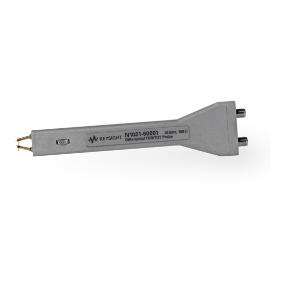
- Page 1 Keysight N1021B 18 GHz Differential TDR/TDR Probe Kit User’s Guide...
- Page 2 Notices Warranty © Keysight Technologies, Inc. 2009 - 2014 (June 1987) or DFAR 252.227-7015 (b)(2) (November 1995), as applicable in any tech- No part of this manual may be reproduced in The material contained in this document is nical data.
-
Page 3: Table Of Contents
Contents Keysight N1021B—At a Glance / 5 Supplied Accessories / 6 Using the Probe / 7 Proper Handling Techniques / 7 Adjusting the Probe Tip Separation / 9 Calibrating the Probe / 10 Performing an Operation Verification / 11 Probing a Differential Trace’s Length Midpoint / 12... - Page 4 Contents User’s Guide...
-
Page 5: Keysight N1021B-At A Glance
RF connectors are unavailable. It is ideal for use with the Keysight N1055A and 54754A TDR plug-in modules. Although the N1021B probe was designed for TDR applications, it is also suitable as a high bandwidth, passive probe for non-TDR applications. -
Page 6: Supplied Accessories
The information on the actual shipping list is more accurate and should supersede the information in this list. To order the parts listed in the table, search for “Parts” at www.keysight.com/find/parts. There are no replaceable parts on the probe. -
Page 7: Using The Probe
- Hand tighten the cable connection to the probe. Or, use a 5 in-lb (0.56 Nm) torque wrench. - Before cleaning the external case parts of the N1021B, disconnect the probe from all cables. Use a dry cloth or one slightly dampened with a mild soap and water solution. - Page 8 N1021B Probe Kit Figure 2 Proper Handling Technique User’s Guide...
-
Page 9: Adjusting The Probe Tip Separation
N1021B Probe Kit Adjusting the Probe Tip Separation Turn the probe spacing adjustment wheel to change the spacing between the probe tips. Avoid using excessive force at the limits of the adjustment range. Figure 3 Probe Tip Spacing Adjustment User’s Guide... -
Page 10: Calibrating The Probe
Place the 86100D In TDR mode, and open the TDR Calibration Setup dialog box. For the TDR setup, connect the N1021B kit’s phase-matched cables to the TDR module’s TDR ports as the TDR test setup cables. The N1021B probe will be the DUT (Device-Under-Test) for this procedure. -
Page 11: Performing An Operation Verification
N1021B Probe Kit Performing an Operation Verification There are no warranted product specifications to measure product performance against. Use this TDR measurement to confirm if the probe is operational. For additional information on TDR measurements, refer to the 86100D online help. -
Page 12: Probing A Differential Trace's Length Midpoint
N1021B Probe Kit Probing a Differential Trace’s Length Midpoint What are the effects of probing a differential trace midway along the trace’s length? At the probe’s tip, the TDR pulse splits into two parts traveling in opposing directions away from the probe. -
Page 13: Probe Characteristics
N1021B Probe Kit Probe Characteristics The following are nominal characteristics of the probe and do not describe warranted performance. However, performance which is deemed grossly different than the listed characteristics will be covered by a 1 year warranty. Table 2... -
Page 14: Returning The Probe For Service
- In the Americas, call 1 (800) 829-4444 - Visit http://www.keysight.com/find/assist If the probe is still under warranty or is covered by an Keysight maintenance contract, it will be repaired under the terms of the warranty or contract. If the probe is no longer under warranty or is not covered by an Keysight maintenance plan, Keysight will notify you of the cost of the repair after examining the unit.
Need help?
Do you have a question about the N1021B and is the answer not in the manual?
Questions and answers