Lenovo ThinkSystem SR675 V3 User Manual
Hide thumbs
Also See for ThinkSystem SR675 V3:
- Manual (200 pages) ,
- System configuration manual (86 pages)
Table of Contents
Advertisement
Quick Links
Advertisement
Table of Contents
Troubleshooting

Related Manuals for Lenovo ThinkSystem SR675 V3


Summary of Contents for Lenovo ThinkSystem SR675 V3
- Page 1 ThinkSystem SR675 V3 User Guide Machine Type: 7D9Q and 7D9R...
- Page 2 Before using this information and the product it supports, be sure to read and understand the safety information and the safety instructions, which are available at: https://pubs.lenovo.com/safety_documentation/ In addition, be sure that you are familiar with the terms and conditions of the Lenovo warranty for your server, which can be found at: http://datacentersupport.lenovo.com/warrantylookup First Edition (June 2023) ©...
-
Page 3: Table Of Contents
Server package contents ... 2.5-inch drive backplane replacement ..159 Identify the server and access the Lenovo XClarity Controller .... - Page 4 ....259 Chapter 7. System configuration . . . 215 Set the network connection for the Lenovo XClarity Appendix B. Getting help and Controller .
-
Page 5: Safety
Vor der Installation dieses Produkts die Sicherheitshinweise lesen. Prima di installare questo prodotto, leggere le Informazioni sulla Sicurezza. Les sikkerhetsinformasjonen (Safety Information) før du installerer dette produktet. Antes de instalar este produto, leia as Informações sobre Segurança. © Copyright Lenovo 2023, 2023... -
Page 6: Safety Inspection Checklist
1 & IEC 60950-1, the standard for Safety of Electronic Equipment within the Field of Audio/Video, Information Technology and Communication Technology. Lenovo assumes you are qualified in the servicing of equipment and trained in recognizing hazards energy levels in products. Access to the equipment is by the use of a tool, lock and key, or other means of security, and is controlled by the authority responsible for the location. - Page 7 Click Power ➙ Power Cables to see all line cords. • Make sure that the insulation is not frayed or worn. 3. Check for any obvious non-Lenovo alterations. Use good judgment as to the safety of any non-Lenovo alterations.
- Page 8 ThinkSystem SR675 V3 User Guide...
-
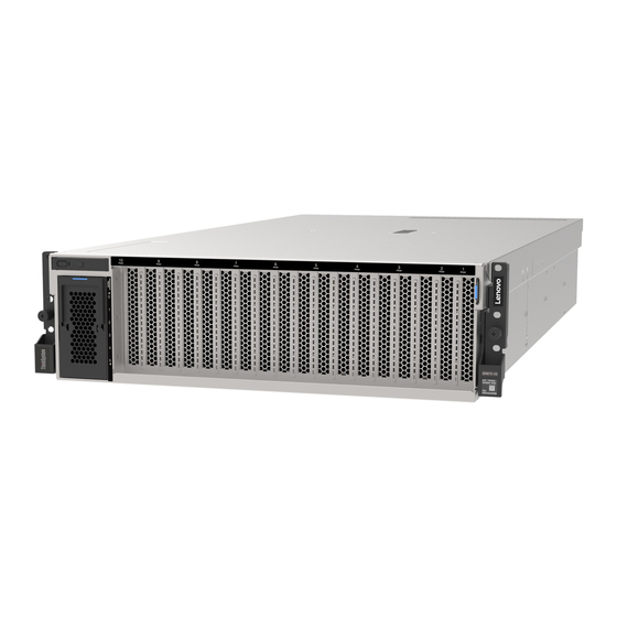
Page 9: Chapter 1. Introduction
Chapter 1. Introduction The ThinkSystem SR675 V3 server (Types 7D9Q and 7D9R) is a 3U rack server designed for high-volume network transaction processing. This high-performance, multi-core server is ideally suited for networking environments that require superior microprocessor performance, input/output (I/O) flexibility, and high manageability. - Page 10 The server provides a QR code on the system service label, which is on the cover of the server, that you can scan using a QR code reader and scanner with a mobile device to get quick access to the Lenovo Service Information website.
-
Page 11: Tech Tips
Tech Tips Lenovo continually updates the support website with the latest tips and techniques that you can use to solve issues that your server might encounter. These Tech Tips (also called retain tips or service bulletins) provide procedures to work around issues or solve problems related to the operation of your server. -
Page 12: Technical Specifications
• Up to eight 2.5-inch hot-swap SAS/SATA/NVMe drives The 8-DW GPU Model supports one of the following storage configurations: • Up to six E1.S 5.9mm hot-swap drives • Up to four E3.S 1T hot-swap drives ThinkSystem SR675 V3 User Guide... - Page 13 • Lenovo XClarity Controller (XCC), which provides service processor control and monitoring functions, video controller, and remote keyboard, video, mouse, and remote drive capabilities. – The server supports Lenovo XClarity Controller 2 (XCC2). For additional information about Lenovo XClarity Controller 2 (XCC2), refer to https://sysmgt.lenovofiles.com/help/topic/lxcc_frontend/lxcc_overview.html...
- Page 14 • One boot drive, M.2, 2.5-inch, EDSFF E1.S 5.9mm drive, or E3.S 1T drive and RAID adapter if configured. (If OS is needed by debugging) • Five system fans • One OCP module with required cable (if network is required) ThinkSystem SR675 V3 User Guide...
-
Page 15: Mechanical Specifications
• Red Hat Enterprise Linux • SUSE Linux Enterprise Server • Canonical Ubuntu References: • Complete list of available operating systems: https://lenovopress.lenovo.com/osig • OS deployment instructions, see “Deploy the operating system” on page 222. Mechanical specifications Summary of the mechanical specifications of server. Depending on the model, some features might not be available, or some specifications might not apply. - Page 16 Lenovo recommends that you consult with qualified experts in this field to determine whether you are in compliance with the applicable regulations.
- Page 17 If Lenovo determines that the levels of particulates or gases in your environment have caused damage to the device, Lenovo may condition provision of repair or replacement of devices or parts on implementation of appropriate remedial measures to mitigate such environmental contamination.
-
Page 18: Management Options
Management options The XClarity portfolio and other system management options described in this section are available to help you manage the servers more conveniently and efficiently. ThinkSystem SR675 V3 User Guide... - Page 19 • Redfish API Usage and downloads https://sysmgt.lenovofiles.com/help/topic/lxcc_frontend/lxcc_overview.html Application that reports the XCC events to local OS system log. Interface • CLI application Lenovo XCC Logger Utility Usage and downloads https://sysmgt.lenovofiles.com/help/topic/lxcc-logger-frontend/lxcc-logger-overview.html Centralized interface for multi-server management. Interface • Web GUI interface •...
- Page 20 Important: Lenovo XClarity Provisioning Manager (LXPM) supported version varies by product. All versions of Lenovo XClarity Provisioning Manager are referred to as Lenovo XClarity Provisioning Manager and LXPM in this document, unless specified otherwise. To see the LXPM version supported by your server, go to https:// sysmgt.lenovofiles.com/help/topic/lxpm_frontend/lxpm_product_page.html...
- Page 21 1. Most options can be updated through the Lenovo tools. Some options, such as GPU firmware or Omni- Path firmware require the use of supplier tools. 2. The server UEFI settings for option ROM must be set to Auto or UEFI to update firmware using Lenovo XClarity Administrator, Lenovo XClarity Essentials, or Lenovo XClarity Controller.
- Page 22 ThinkSystem SR675 V3 User Guide...
-
Page 23: Chapter 2. Server Components
This section contains information about each of the components associated with the server. Front view The illustrations in this section provide information about the front view of the server. The ThinkSystem SR675 V3 front view varies by model. Refer to the front view specific to each model to identify the components. •... -
Page 24: The 8-Dw Gpu Model Front View
“Front view with 6x E1.S 5.9mm drives” on page 16 • “Front view with 4x E3.S 1T drives” on page 18 Front view with 6x E1.S 5.9mm drives Figure 3. Front view with 6x E1.S 5.9mm drives ThinkSystem SR675 V3 User Guide... - Page 25 Table 3. Components on the front view with 6x E1.S 5.9mm drives EDSFF drive cage cover PCIe slot 3-10 Front operator panel PCIe Slot 1-2 Drive activity LED (green) E1.S 5.9mm hot-swap drive bays (0 to 5) Drive status LED (yellow) EDSFF drive cage cover The 8-DW GPU Model servers should always operate with the EDSFF drive cage cover installed to the chassis.
- Page 26 • The LED is flashing rapidly (three times per second): the drive is being identified. PCIe slot 3-10 Install PCIe adapters, particularly GPUs to these slots. These PCIe slots support the following configuration: • PCIe Gen5 x16, FH/FL PCIe slot 1-2 ThinkSystem SR675 V3 User Guide...
-
Page 27: Rear View
Install PCIe adapters, particularly network adapters to these slots. These PCIe slots support the following configuration: • PCIe Gen5 x16, FH/FL E3.S 1T hot-swap drive bays (0 to 3) Install E3.S 1T hot-swap drives to these bays. See “Install an E1.S / E3.S hot-swap drive” on page 166 more information. - Page 28 Connect a monitor to this connector. XCC system management port (1 GB RJ-45) The server has a 1 GB RJ-45 connector dedicated to Lenovo XClarity Controller (XCC) functions. Through the system management port, you can access the Lenovo XClarity Controller directly by connecting your laptop to the management port using an Ethernet cable.
-
Page 29: Top View
Figure 8. Port numbering — 4-port OCP 3.0 module Top view The illustrations in this section provide information about the top view of the server. The ThinkSystem SR675 V3 top view varies by model. Refer to the top view specific to each model to identify the components. •... -
Page 30: The 8-Dw Gpu Model Top View
Note: The illustration shows the location of certain parts. Some parts may not be supported at the same time within certain configuration(s). The 8-DW GPU Model top view This section contains information on the top view of the 8-DW GPU Model server. ThinkSystem SR675 V3 User Guide... -
Page 31: Front I/O Module
Figure 10. Top view of the 8-DW GPU Model Table 7. Components on the top view of the 8-DW GPU Model PCIe riser 1 GPU adapters System board assembly Front operator panel PCIe riser 2 EDSFF drive cage assembly Memory modules Processor 2 Processor 1 Power distribution board... - Page 32 Note: This is the only USB port that supports USB automation update of the firmware and RoT security module. Connection to Lenovo XClarity Controller is primarily intended for users with a mobile device running the Lenovo XClarity Controller mobile application. When a mobile device is connected to this USB port, an Ethernet over USB connection is established between the mobile application running on the device and the Lenovo XClarity Controller.
-
Page 33: System-Board-Assembly Layout
In this mode, connection to the USB port is shared by the server and Lenovo XClarity Controller, while the port is switched to Lenovo XClarity Controller. • Shared mode: owned by host In this mode, connection to the USB port is shared by the server and Lenovo XClarity Controller, while the port is switched to the server. -
Page 34: System-Board-Assembly Connectors
Backplane power connector Front USB connector LCD connector M.2 power connector Front operator panel connector M.2 signal connector Fan 5 connector Memory module slot 1-6 (right to left) PCIe connector 5, 7 (right to left) ThinkSystem SR675 V3 User Guide... -
Page 35: System-Board-Assembly Switches
Table 9. System-board-assembly connectors (continued) Processor 1 PCIe 8 connector PCIe connector 4 PCIe 6 connector PCIe connector 2 Processor 2 PCIe connector 1, 3 (right to left) Memory module slot 19-24 (right to left) Front riser power connector Memory module slot 7-18 (right to left) Fan 1 connector Power distribution board connector PCIe distribution board power connector... - Page 36 Off: XCC boots from upper half of flash region. BMC boot primary On: XCC boots from lower half of flash region. Changing this switch to the On position forces XCC to Force BMC update boot from kernel code only. ThinkSystem SR675 V3 User Guide...
-
Page 37: System Leds And Diagnostics Display
Table 11. Switch block 6 (SW6) description (continued) Default Switch Description Definition position number Changing this switch to the On position ignores Power Power permission override Permission and allows the system to power-on. Changing this switch to the On position forces XCC into Force BMC reset reset. - Page 38 ThinkSystem SR675 V3 User Guide...
-
Page 39: Chapter 3. Parts List
Chapter 3. Parts list Use the parts list to identify each of the components that are available for your server. The ThinkSystem SR675 V3 parts list varies by model. Refer to the parts list specific to each model to identify the components. - Page 40 Tier 1 CRU at your request with no service agreement, you will be charged for the installation. • Tier 2 customer replaceable unit (CRU): You may install a Tier 2 CRU yourself or request Lenovo to install it, at no additional charge, under the type of warranty service that is designated for your server.
- Page 41 For more information about ordering parts: 1. Go to and navigate to the support page for your server. http://datacentersupport.lenovo.com 2. Click Parts. 3. Enter the serial number to view a listing of parts for your server. Top cover √...
-
Page 42: The 8-Dw Gpu Model (E1.S Drive Configuration) Parts List
2. Click Parts. 3. Enter the serial number to view a listing of parts for your server. It is highly recommended that you check the power summary data for your server using Lenovo Capacity Planner before purchasing any new parts. - Page 43 Tier 1 CRU at your request with no service agreement, you will be charged for the installation. • Tier 2 customer replaceable unit (CRU): You may install a Tier 2 CRU yourself or request Lenovo to install it, at no additional charge, under the type of warranty service that is designated for your server.
- Page 44 E1.S drive backplane √ E1.S drive cage (with cage cover) √ E1.S drive filler (1-bay) √ E1.S hot-swap drive √ Chassis √ Cable √ Front operator panel √ GPU adapter link bridge √ √ Double-wide GPU ThinkSystem SR675 V3 User Guide...
-
Page 45: The 8-Dw Gpu Model (E3.S Drive Configuration) Parts List
2. Click Parts. 3. Enter the serial number to view a listing of parts for your server. It is highly recommended that you check the power summary data for your server using Lenovo Capacity Planner before purchasing any new parts. - Page 46 Tier 1 CRU at your request with no service agreement, you will be charged for the installation. • Tier 2 customer replaceable unit (CRU): You may install a Tier 2 CRU yourself or request Lenovo to install it, at no additional charge, under the type of warranty service that is designated for your server.
- Page 47 For more information about ordering parts: 1. Go to and navigate to the support page for your server. http://datacentersupport.lenovo.com 2. Click Parts. 3. Enter the serial number to view a listing of parts for your server. Top cover √...
-
Page 48: Power Cords
The cord set should have the appropriate safety approvals for the country in which the equipment will be installed. • Power cords for a specific country or region are usually available only in that country or region. ThinkSystem SR675 V3 User Guide... -
Page 49: Chapter 4. Unboxing And Setup
They might be required to receive warranty service. Identify the server and access the Lenovo XClarity Controller This section contains instruction on how to identify your server and where to find the Lenovo XClarity Controller access information. - Page 50 Lenovo XClarity Controller network access label In addition, the Lenovo XClarity Controller network access label is attached to the pull-out information tab located near the upper right corner in the front of the chassis, with MAC address accessible with a pull.
-
Page 51: Server Setup Checklist
Figure 20. Service Label and QR code Server setup checklist Use the server setup checklist to ensure that you have performed all tasks that are required to set up your server. The server setup procedure varies depending on the configuration of the server when it was delivered. In some cases, the server is fully configured and you just need to connect the server to the network and an AC power source, and then you can power on the server. - Page 52 • You can press the power button. • The server can restart automatically after a power interruption. • The server can respond to remote power-on requests sent to the Lenovo XClarity Controller. Note: You can access the management processor interface to configure the system without powering on the server.
-
Page 53: Chapter 5. Hardware Replacement Procedures
• Do not attempt to lift an object that might be too heavy for you. If you have to lift a heavy object, read the following precautions carefully: – Make sure that you can stand steadily without slipping. – Distribute the weight of the object equally between your feet. © Copyright Lenovo 2023, 2023... -
Page 54: Safety Inspection Checklist
1 & IEC 60950-1, the standard for Safety of Electronic Equipment within the Field of Audio/Video, Information Technology and Communication Technology. Lenovo assumes you are qualified in the servicing of equipment and trained in recognizing hazards energy levels in products. Access to the equipment is by the use of a tool, lock and key, or other means of security, and is controlled by the authority responsible for the location. -
Page 55: System Reliability Guidelines
Click Power ➙ Power Cables to see all line cords. • Make sure that the insulation is not frayed or worn. 3. Check for any obvious non-Lenovo alterations. Use good judgment as to the safety of any non-Lenovo alterations. -
Page 56: Handling Static-Sensitive Devices
• When handling a device, carefully hold it by the edges or the frame. • Do not touch solder joints, pins, or exposed circuitry. • Keep the device from others’ reach to prevent possible damages. ThinkSystem SR675 V3 User Guide... -
Page 57: Memory Module Installation Rules And Order
Supported memory types For information on the types of memory module supported by this server, see “Memory” section in “Technical specifications” on page Information about optimizing memory performance and configuring memory is available at the Lenovo Press website: https://lenovopress.lenovo.com/servers/options/memory In addition, you can take advantage of a memory configurator, which is available at the following site: https://dcsc.lenovo.com/#/memory_configuration... -
Page 58: Independent Memory Mode Installation Order
Memory module installation guideline The ThinkSystem SR675 V3 supports “Independent memory mode installation order” on page Independent memory mode installation order In independent memory mode, memory channels can be populated with DIMMs in any order and you can populate all channels for each processor in any order with no matching requirements. - Page 59 Independent memory mode guidelines: • Populate identical memory capacity and rank per memory channel and processor. • Mixing x4/x8, EC4/EC8, 3DS/Non-3DS RDIMM, 4Rank 3DS/8Rank 3DS RDIMM are not allowed in a system. • Dual Socket (2P) socket interleaving (NPS0, dual socket system as one NUMA node) can be supported only if: 1.
- Page 60 ThinkSystem SR675 V3 User Guide...
-
Page 61: Power On And Power Off The Server
• You can press the power button. • The server can restart automatically after a power interruption. • The server can respond to remote power-on requests sent to the Lenovo XClarity Controller. For information about powering off the server, see “Power off the server”... -
Page 62: Power Off The Server
Power off the server The server remains in a standby state when it is connected to a power source, allowing the Lenovo XClarity Controller to respond to remote power-on requests. To remove all power from the server (power status LED off), you must disconnect all power cables. - Page 63 Attention: • Read “Installation Guidelines” on page 45 “Safety inspection checklist” on page 46 to ensure that you work safely. • Power off the server and peripheral devices and disconnect the power cords and all external cables. See “Power off the server” on page CAUTION: Make sure to have three people operate the server removal procedures to prevent injury.
- Page 64 Figure 24. Lifting up the server Lift point Press the release tabs to disengage the rails from the server. Carefully lift up the front end of the server slightly to detach the nailheads from the slots on the rails. ThinkSystem SR675 V3 User Guide...
-
Page 65: Install The Server To Rack
With three people, lift up the serve to remove it from the rails completely. Place the server on a flat and sturdy surface. Rack Front Figure 25. Removing the server from the rack Release tab After you finish Carefully lay the server on a flat, static-protective surface. Install the server to rack Follow instructions in this section to install the server to the rack. - Page 66 Make sure to have three people operate the server installation procedures to prevent injury. Procedure Step 1. From the front of the rack, pull the rails all the way out until they stop Attention: You can only install the server successfully when the rails are fully extended. ThinkSystem SR675 V3 User Guide...
- Page 67 Rack front Figure 26. Pulling out the rails Chapter 5 Hardware replacement procedures...
- Page 68 Step 2. Carefully lift up the server with three people. CAUTION: Make sure three people are lifting the sever by holding the lift points Rack front Figure 27. Lifting up the server Lift point ThinkSystem SR675 V3 User Guide...
- Page 69 Step 3. From the front of the rack, install server into the rails. Tilt the server and slowly lower the rear end; then, push the rails toward the server and make sure the farthest nailheads on server’s left and right side go into the slots on the rail. Slowly lower the server down and make sure the other 3 nailheads on server’s left and right side slip into corresponding slots.
- Page 70 Figure 29. Installing the server into the rack Latch ThinkSystem SR675 V3 User Guide...
- Page 71 Step 5. (Optional) Secure the server to the rack. Secure the server to the rear of the rack. Select the first rail you want to secure. Insert a washer and M5 screw; then, fasten the M5 screw. Repeat to secure the other rail. Rack rear Figure 30.
-
Page 72: Remove The Rails From The Rack
• The illustrations in this document are for reference only and might differ slightly from your hardware. • The replacement procedures in this section uses the 4-DW GPU Model as an example, the replacement procedures for the 8-DW GPU Model are similar. ThinkSystem SR675 V3 User Guide... -
Page 73: Air Baffle Replacement
Air baffle replacement Follow instructions in this section to remove and install the air baffle. Remove the air baffle Follow instructions in this section to remove the air baffle. About this task Attention: • Read “Installation Guidelines” on page 45 “Safety inspection checklist”... - Page 74 Grasp the air baffle and carefully lift it out of the chassis. Attention: For proper cooling and airflow, reinstall the air baffle before you turn on the server. Operating the server with the air baffle removed might damage server components. Figure 33. Air baffle removal ThinkSystem SR675 V3 User Guide...
- Page 75 After you finish 1. If you are instructed to return the component or optional device, follow all packaging instructions, and use any packaging materials for shipping that are supplied to you. 2. Remove the M.2 backplane from the air baffle. See “Remove the M.2 backplane”...
- Page 76 Figure 35. M.2 backplane cable connection Figure 36. M.2 signal and power connector locations M.2 power connector M.2 signal connector 2. Complete the parts replacement. See “Complete the parts replacement” on page 194. ThinkSystem SR675 V3 User Guide...
-
Page 77: Cmos Battery (Cr2032) Replacement
Follow instructions in this section to remove the CMOS battery (CR2032). • Lenovo has designed this product with your safety in mind. The lithium battery must be handled correctly to avoid possible danger. If you replace the battery, you must adhere to the following instructions. - Page 78 Figure 37. CMOS battery removal After you finish Dispose the component with compliance to local regulations. Install the CMOS battery (CR2032) Follow instructions in this section to install the CMOS battery (CR2032). S005 ThinkSystem SR675 V3 User Guide...
- Page 79 CAUTION: The battery is a lithium ion battery. To avoid possible explosion, do not burn the battery. Exchange it only with the approved part. Recycle or discard the battery as instructed by local regulations. About this task Attention: Read “Installation Guidelines” on page 45 “Safety inspection checklist”...
-
Page 80: External Diagnostics Handset Replacement
To avoid possible danger, read and follow the following safety statement. • S014 CAUTION: Hazardous voltage, current, and energy levels might be present. Only a qualified service technician is authorized to remove the covers where the label is attached. • S017 ThinkSystem SR675 V3 User Guide... - Page 81 CAUTION: Hazardous moving fan blades nearby. Keep fingers and other body parts away. • S033 CAUTION: Hazardous energy present. Voltages with hazardous energy might cause heating when shorted with metal, which might result in spattered metal, burns, or both. Attention: •...
- Page 82 Hazardous voltage, current, and energy levels might be present. Only a qualified service technician is authorized to remove the covers where the label is attached. • S017 CAUTION: Hazardous moving fan blades nearby. Keep fingers and other body parts away. • S033 ThinkSystem SR675 V3 User Guide...
- Page 83 CAUTION: Hazardous energy present. Voltages with hazardous energy might cause heating when shorted with metal, which might result in spattered metal, burns, or both. Attention: • Read “Installation Guidelines” on page 45 “Safety inspection checklist” on page 46 to ensure that you work safely.
-
Page 84: Fan Replacement
“Remove the server from rack” on page Watch the procedure A video of this procedure is available at YouTube: https://www.youtube.com/playlist?list=PLYV5R7hVcs- AgTVLhsU24Nhel3_oYlnGT Procedure Step 1. Remove the top cover. See “Remove the top cover” on page 154. Step 2. Remove the fan. ThinkSystem SR675 V3 User Guide... - Page 85 Pinch and hold the blue touch points on the top of the fan. Lift the fan out of the chassis. Figure 42. Fan removal After you finish If you are instructed to return the component or optional device, follow all packaging instructions, and use any packaging materials for shipping that are supplied to you.
-
Page 86: Fan Cage Replacement
• If the server is installed in a rack, slide the server out on its rack slide rails to gain access to the top cover, or remove the server from the rack. See “Remove the server from rack” on page Watch the procedure A video of this procedure is available at YouTube: https://www.youtube.com/playlist?list=PLYV5R7hVcs- AgTVLhsU24Nhel3_oYlnGT Procedure ThinkSystem SR675 V3 User Guide... - Page 87 Step 1. Make preparation for this task. Remove the top cover. See “Remove the top cover” on page 154. Remove all of the fans. See “Remove a fan” on page Step 2. Remove the fan cage. Rotate the two release latches on the fan cage up to disengage it from the chassis. Hold the handles, and lift the fan cage out of the chassis.
-
Page 88: Flash Power Module Replacement
“Remove the top cover” on page 154. Disconnect the cable from the flash power module. Remove the PCIe riser where the flash power module has been installed. See “Remove a PCIe riser” on page 110. ThinkSystem SR675 V3 User Guide... - Page 89 Step 2. Remove the flash power module. Open the retention latch on the PCIe riser. Unfasten the screw that secures the flash power module holder bracket to the PCIe riser. Remove the holder bracket from the PCIe riser. Press and release the retaining latch. Remove the flash power module from the holder.
- Page 90 Step 2. Close the retaining latch. Step 3. Insert the holder bracket into the PCIe riser. Step 4. Fasten the screw to secure the holder bracket to the PCIe riser. Step 5. Close the retention latch. ThinkSystem SR675 V3 User Guide...
-
Page 91: Front I/O Module Replacement
Figure 48. Flash power module installation Step 6. Connect the cable to the corresponding RAID adapter. After you finish 1. Reinstall the PCIe riser. See “Install a PCIe riser” on page 115. 2. Complete the parts replacement. See “Complete the parts replacement” on page 194. - Page 92 “The 4-DW GPU Model front view” on page 15 Step 2. Install the front I/O module. Note: If the front I/O module slot is covered with a slot bracket, remove the bracket from the chassis first. ThinkSystem SR675 V3 User Guide...
-
Page 93: Front Operator Panel Replacement
Insert the front I/O module into the front I/O module slot. Ensure that the module is fully seated. Fasten the front I/O module retention screw. Figure 50. Front I/O module installation Step 3. Connect the front USB, video and external diagnostics handset cables from the front I/O module to their respective connectors on the system board assembly. - Page 94 Step 3. Remove the front operator panel. Press and hold on the two release tabs on the top of the drive bays. Grasp and pull the front operator panel to remove it from the server. ThinkSystem SR675 V3 User Guide...
- Page 95 Figure 52. Front operator panel removal After you finish If you are instructed to return the component or optional device, follow all packaging instructions, and use any packaging materials for shipping that are supplied to you. Install the front operator panel Follow instructions in this section to install the front operator panel.
- Page 96 Figure 53. Front operator panel installation Step 3. Reconnect the front operator panel cable to the system board assembly as illustrated. ThinkSystem SR675 V3 User Guide...
-
Page 97: Intrusion Switch Replacement
Cable From System board assembly: Front operator panel Front operator panel connector Figure 54. Front operator panel cable connection After you finish Complete the parts replacement. See “Complete the parts replacement” on page 194. Intrusion switch replacement Follow instructions in this section to remove and install the intrusion switch. Remove the intrusion switch Follow instructions in this section to remove the intrusion switch. - Page 98 Figure 55. Intrusion switch removal After you finish If you are instructed to return the component or optional device, follow all packaging instructions, and use any packaging materials for shipping that are supplied to you. ThinkSystem SR675 V3 User Guide...
- Page 99 Install the intrusion switch Follow instructions in this section to install the intrusion switch. About this task Attention: • Read “Installation Guidelines” on page 45 “Safety inspection checklist” on page 46 to ensure that you work safely. • Touch the static-protective package that contains the component to any unpainted metal surface on the server;...
-
Page 100: M.2 Backplane And M.2 Drive Replacement
See “Remove the server from rack” on page • If one or more NVMe solid-state drives are to be removed, it is recommended to disable them beforehand via the operating system. ThinkSystem SR675 V3 User Guide... - Page 101 • Before you remove or make changes to drives, drive controllers (including controllers that are integrated on the system board assembly), drive backplanes or drive cables, back up all important data that is stored on drives. • Before you remove any component of a RAID array (drive, RAID card, etc.), back up all RAID configuration information.
- Page 102 Step 2. Disconnect the M.2 backplane cables from the system board assembly. Press and hold the latches on the M.2 cables. Disconnect the cables from the system board assembly. Figure 59. M.2 backplane cable disconnection ThinkSystem SR675 V3 User Guide...
- Page 103 Step 3. Remove the air baffle from the server and place it on a static-protective surface. See “Remove the air baffle” on page Step 4. Remove the M.2 backplane. Remove the screw that secures the end of the M.2 backplane to the air baffle. Remove the screw that secures the middle of the M.2 backplane to the air baffle Slide the M.2 backplane backward, and lift it out of the air baffle.
- Page 104 Lower the M.2 backplane into the air baffle; then, slide the M.2 backplane forward until it is seated in place. Install the screw that secures the middle of the M.2 backplane to the air baffle Install the screw that secures the end of the M.2 backplane to the air baffle. ThinkSystem SR675 V3 User Guide...
- Page 105 Figure 63. M.2 backplane installation Step 4. Reinstall the air baffle in the server. See “Install the air baffle” on page Step 5. Connect the M.2 backplane cables to the M.2 power connector and the signal connector on the system board assembly. Figure 64.
- Page 106 Locate the connector you want to install the M.2 drive on the M.2 backplane. Step 2. If needed, adjust the position of the M.2 drive retainer so that it is compatible with the size of the M.2 drive you are installing. ThinkSystem SR675 V3 User Guide...
-
Page 107: Memory Module Replacement
Step 3. Slide the M.2 retainer backward to ensure enough space for the M.2 drive installation. Step 4. Install the M.2 drive. Hold the M.2 drive at an angle, and insert it into the M.2 slot. Lower the M.2 drive. Slide the retainer toward the M.2 drive to secure it in place. - Page 108 Remove the top cover. See “Remove the top cover” on page 154. Remove the air baffle. See “Remove the air baffle” on page Locate the memory module slots and determine which memory module to be removed. ThinkSystem SR675 V3 User Guide...
- Page 109 Figure 67. Memory modules and processors layout Step 2. If necessary, remove a cable guide from the chassis wall to access the memory module slots. Figure 68. Cable guide removal Chapter 5 Hardware replacement procedures...
- Page 110 • Make sure to remove or install memory module 20 seconds after disconnecting power cords from the system. It allows the system to be completely discharged of electricity and safe for handling memory module. ThinkSystem SR675 V3 User Guide...
- Page 111 Important: Remove or install memory modules for one processor at a time. Firmware and driver download: You might need to update the firmware or driver after replacing a component. • Go to https://datacentersupport.lenovo.com/tw/en/products/servers/thinksystem/sr675v3/7d9q/downloads/ driver-list/ to see the latest firmware and driver updates for your server. • Go to “Update the firmware”...
- Page 112 Figure 70. Memory modules and processors layout ThinkSystem SR675 V3 User Guide...
- Page 113 Step 3. Install the memory module into the slot. Gently open the retaining clip on each end of the memory module slot. Align the memory module with the slot, and gently place the memory module on the slot with both hands. Firmly press both ends of the memory module straight down into the slot until the retaining clips snap into the locked position.
-
Page 114: Network Adapter Replacement
“Remove the server from rack” on page Watch the procedure A video of this procedure is available at YouTube: https://www.youtube.com/playlist?list=PLYV5R7hVcs- AgTVLhsU24Nhel3_oYlnGT Procedure Step 1. Remove the top cover. See “Remove the top cover” on page 154. ThinkSystem SR675 V3 User Guide... - Page 115 Step 2. Unfasten the screw that secures the network adapter to the chassis; then, lift the network adapter out of the PCIe slot. Figure 73. Network adapter removal After you finish If you are instructed to return the component or optional device, follow all packaging instructions, and use any packaging materials for shipping that are supplied to you.
-
Page 116: Ocp Module Replacement
• Power off the server and peripheral devices and disconnect the power cords and all external cables. See “Power off the server” on page Watch the procedure A video of this procedure is available at YouTube: https://www.youtube.com/playlist?list=PLYV5R7hVcs- AgTVLhsU24Nhel3_oYlnGT Procedure Step 1. Loosen the thumbscrew. ThinkSystem SR675 V3 User Guide... - Page 117 Step 2. Grasp the handle and slide the OCP module out. Figure 75. OCP module removal After you finish If you are instructed to return the component or optional device, follow all packaging instructions, and use any packaging materials for shipping that are supplied to you. Install the OCP module Follow instructions in this section to install the OCP module.
-
Page 118: Pcie Riser And Pcie Adapter Replacement
A video of this procedure is available at YouTube: https://www.youtube.com/playlist?list=PLYV5R7hVcs- AgTVLhsU24Nhel3_oYlnGT Select the PCIe riser removal scenario There are three PCIe riser removal scenarios differentiated by PCIe riser location and serial port installation. See corresponding instructions below for proper removal procedure. ThinkSystem SR675 V3 User Guide... - Page 119 Figure 77. PCIe riser locations • “Remove a PCIe riser without serial port module” on page 111 • “Remove PCIe riser 1 installed with serial port module” on page 112 • “Remove PCIe riser 2 installed with serial port module” on page 113 Remove a PCIe riser without serial port module Procedure Step 1.
- Page 120 “Remove a PCIe adapter” on page 113. 3. If you are instructed to return the component or optional device, follow all packaging instructions, and use any packaging materials for shipping that are supplied to you. ThinkSystem SR675 V3 User Guide...
- Page 121 Remove PCIe riser 2 installed with serial port module Procedure Step 1. Make preparation for this task. Remove the top cover. See “Remove the top cover” on page 154. Disconnect the cables that are connected to the PCIe riser and the PCIe adapter. Step 2.
- Page 122 If you are instructed to return the component or optional device, follow all packaging instructions, and use any packaging materials for shipping that are supplied to you. Install a PCIe adapter Follow instructions in this section to install a PCIe adapter. About this task Attention: ThinkSystem SR675 V3 User Guide...
- Page 123 • Read “Installation Guidelines” on page 45 “Safety inspection checklist” on page 46 to ensure that you work safely. • Touch the static-protective package that contains the component to any unpainted metal surface on the server; then, remove it from the package and place it on a static-protective surface. Watch the procedure A video of this procedure is available at YouTube: https://www.youtube.com/playlist?list=PLYV5R7hVcs-...
- Page 124 Align the guide hole on the PCIe riser with the guide post on the system board assembly; then, insert the PCIe riser into the PCIe slot on the system board assembly. Step 2. Fasten the thumbscrew to secure the PCIe riser. ThinkSystem SR675 V3 User Guide...
- Page 125 Figure 84. PCIe riser installation (without serial port module) After you finish 1. Reconnect the required cables. 2. Complete the parts replacement. See “Complete the parts replacement” on page 194. Install PCIe riser 1 installed with serial port module Procedure Step 1.
- Page 126 Align the guide hole on the PCIe riser with the guide post on the system board assembly; then, insert the PCIe riser into the PCIe slot on the system board assembly. Fasten the thumbscrew to secure the PCIe riser. ThinkSystem SR675 V3 User Guide...
-
Page 127: Pcie Riser Card Replacement
Figure 86. PCIe riser 2 installation (with serial port module) After you finish 1. Reconnect the required cables. 2. Complete the parts replacement. See “Complete the parts replacement” on page 194. PCIe riser card replacement Follow instructions in this section to remove and install a PCIe riser card. Remove a PCIe riser card Follow instructions in this section to remove a PCIe riser card. - Page 128 Install a PCIe riser card Follow instructions in this section to install a PCIe riser card. About this task Attention: • Read “Installation Guidelines” on page 45 “Safety inspection checklist” on page 46 to ensure that you work safely. ThinkSystem SR675 V3 User Guide...
-
Page 129: Power Distribution Board Replacement
• Touch the static-protective package that contains the component to any unpainted metal surface on the server; then, remove it from the package and place it on a static-protective surface. Watch the procedure A video of this procedure is available at YouTube: https://www.youtube.com/playlist?list=PLYV5R7hVcs- AgTVLhsU24Nhel3_oYlnGT Procedure... - Page 130 If you are instructed to return the component or optional device, follow all packaging instructions, and use any packaging materials for shipping that are supplied to you. Install the power distribution board Follow instructions in this section to install the power distribution board. ThinkSystem SR675 V3 User Guide...
-
Page 131: Power Supply Unit Replacement
About this task Attention: Read “Installation Guidelines” on page 45 “Safety inspection checklist” on page 46 to ensure that you work safely. Watch the procedure A video of this procedure is available at YouTube: https://www.youtube.com/playlist?list=PLYV5R7hVcs- AgTVLhsU24Nhel3_oYlnGT Procedure Step 1. Align the connector on the power distribution board with that on the system board assembly with the two power supply connectors facing the power supply bays;... - Page 132 2. If you are instructed to return the component or optional device, follow all packaging instructions, and use any packaging materials for shipping that are supplied to you. Install a power supply unit Follow instructions in this section to install a power supply unit. ThinkSystem SR675 V3 User Guide...
- Page 133 About this task Attention: • Read “Installation Guidelines” on page 45 “Safety inspection checklist” on page 46 to ensure that you work safely. • Touch the static-protective package that contains the component to any unpainted metal surface on the server; then, remove it from the package and place it on a static-protective surface. Note: During normal operation, each power supply bay must contain either a power supply unit or a power supply filler for proper cooling.
- Page 134 Make sure that the AC power LED on the power supply unit is lit, indicating that the power supply unit is operating correctly. After you finish Check the PSU LEDs to verify that the PSU is operating correctly. See Figure 6 “Power supply LEDs on the Rear view” on page ThinkSystem SR675 V3 User Guide...
-
Page 135: Processor And Heat Sink Replacement
Follow instructions in this section to remove and install a processor and a heat sink. Important: • This task must be operated by trained technicians that are certified by Lenovo Service. Do no attempt to remove or install it without proper training and qualification. - Page 136 Thermal grease Remove a heat sink Follow instructions in this section to remove a heat sink. This task requires a Torx T20 driver. The procedure must be executed by a trained technician. About this task S002 ThinkSystem SR675 V3 User Guide...
- Page 137 CAUTION: The power-control button on the device and the power switch on the power supply do not turn off the electrical current supplied to the device. The device also might have more than one power cord. To remove all electrical current from the device, ensure that all power cords are disconnected from the power source.
- Page 138 Watch the procedure A video of this procedure is available at YouTube: https://www.youtube.com/playlist?list=PLYV5R7hVcs- AgTVLhsU24Nhel3_oYlnGT Procedure Step 1. Use a Torx T20 screwdriver to loosen the screw; then, slightly lift up the retention frame. ThinkSystem SR675 V3 User Guide...
- Page 139 Notes: • See https://serverproven.lenovo.com for a list of processors supported for your server. All processors on the system board assembly must have the same speed, number of cores, and frequency. • Before you install a new processor, update your system firmware to the latest level. See “Update the...
- Page 140 • Prevent exposure to static electricity, which might lead to system halt and loss of data, by keeping static- sensitive components in their static-protective packages until installation, and handling these devices with an electrostatic-discharge wrist strap or other grounding system. Procedure Step 1. Record the processor identification label. ThinkSystem SR675 V3 User Guide...
- Page 141 To replace a processor and reuse the heat sink: 1. Remove the processor identification label from the heat sink and replace it with the new label that comes with the replacement processor. 2. Wipe off old thermal grease on the heat sink with an alcohol cleaning pad. To replace a heat sink and reuse the processor: 1.
-
Page 142: Serial Port Module Replacement
“Remove the server from rack” on page Watch the procedure A video of this procedure is available at YouTube: https://www.youtube.com/playlist?list=PLYV5R7hVcs- AgTVLhsU24Nhel3_oYlnGT Procedure Step 1. Make preparation for this task. Remove the top cover. See “Remove the top cover” on page 154. ThinkSystem SR675 V3 User Guide... - Page 143 Disconnect the serial port cable from the system board assembly. Remove the PCIe riser where the serial port module has been installed. See “Remove a PCIe riser” on page 110. Step 2. Remove the serial port module. Remove the serial port cable from the cable clip. Open the retention latch on the PCIe riser.
-
Page 144: System Board Assembly Replacement
Follow instructions in this section to remove and install the system board assembly. Important: • This task must be operated by trained technicians that are certified by Lenovo Service. Do no attempt to remove or install it without proper training and qualification. - Page 145 – Check the current PSB fuse policy before replacement. See Service process before replacement at Service process for updating PSB fuse state. – Ensure that the processor fuse status is expected without unexpected XCC event logs after replacement. See Service process after replacing a processor board and a firmware and RoT security module together at Service process for updating PSB fuse state.
- Page 146 Follow instructions in this section to remove the ThinkSystem V3 Firmware and Root of Trust Security Module (firmware and RoT security module). About this task Important: This task must be operated by trained technicians that are certified by Lenovo Service. Do no attempt to remove or install it without proper training and qualification. Attention: •...
- Page 147 Follow instructions in this section to install the ThinkSystem V3 Firmware and Root of Trust Security Module (firmware and RoT security module). About this task Important: This task must be operated by trained technicians that are certified by Lenovo Service. Do no attempt to remove or install it without proper training and qualification. Attention: •...
- Page 148 About this task Important: • This task must be operated by trained technicians that are certified by Lenovo Service. Do no attempt to remove or install it without proper training and qualification. • When replacing the system board assembly, always update the server with the latest firmware or restore the pre-existing firmware.
- Page 149 Procedure Step 1. Make preparation for this task. Record all system configuration information, such as Lenovo XClarity Controller IP addresses, vital product data, and the machine type, model number, serial number, Universally Unique Identifier, and asset tag of the server.
- Page 150 Lifting handles Step 5. Remove the system board assembly. Tilt the system board assembly so that its rear end is up. Hold both lifting handles, and lift the system board assembly out of the chassis. ThinkSystem SR675 V3 User Guide...
- Page 151 Figure 106. System board assembly removal Step 6. (Optional) If you are going to replace the system I/O board, remove the firmware and RoT security module from the system I/O board. See “Remove the firmware and RoT security module” on page 138.
- Page 152 Figure 108. System board assembly disassembly 3. Separate the system board assembly from the supporting sheet metal. Figure 109. System board assembly disassembly Grasp the system I/O board by its edges, and carefully pull it out of the processor board. ThinkSystem SR675 V3 User Guide...
- Page 153 Note: Make sure you have SR675 V3 Misc Kit available to replace the system I/O board and processor board. Firmware and driver download: You might need to update the firmware or driver after replacing a component. • Go to https://datacentersupport.lenovo.com/tw/en/products/servers/thinksystem/sr675v3/7d9q/downloads/ to see the latest firmware and driver updates for your server. driver-list/ Chapter 5 Hardware replacement procedures...
- Page 154 Figure 111. System I/O board installation Install the system board assembly to the supporting sheet metal. 1. Lower the system board assembly into the supporting sheet metal. ThinkSystem SR675 V3 User Guide...
- Page 155 Figure 112. System board assembly installation 2. Install the following components as illustrated: • Two screws on the cable wall bracket (with PH2 screwdriver) • Eleven screws on the system board assembly (with PH1 screwdriver) Figure 113. System board assembly installation 3.
- Page 156 Grasp the two lifting handles on the system board assembly, and tilt the system board assembly so that its rear end is up. Lower the system board assembly into the chassis. Figure 115. System board assembly installation ThinkSystem SR675 V3 User Guide...
- Page 157 Lifting handles Step 4. Grasp the two lifting handles, and slide the system board assembly toward the rear of the chassis until it clicks into place. Make sure that the rear connectors on the new system board assembly are inserted into the corresponding holes in the rear panel. Figure 116.
- Page 158 Using Lenovo XClarity Provisioning Manager Steps: 1. Start the server and press the key according to the on-screen instructions. The Lenovo XClarity Provisioning Manager interface is displayed by default. 2. Choose System Summary. The “System Summary” tab page is displayed.
- Page 159 OneCli.exe config set TrustedComputingGroup.HideTPMfromOS "Yes" --imm <userid>:<password>@<ip_address> --override where: • <userid>:<password> are the credentials used to access the BMC (Lenovo XClarity Controller interface) of your server. The default user ID is USERID, and the default password is PASSW0RD (zero, not an uppercase o) •...
- Page 160 Follow the procedure below to see the TPM firmware version: From Lenovo XClarity Provisioning Manager 1. Start the server and press the key specified in the on-screen instructions to display the Lenovo XClarity Provisioning Manager interface. (For more information, see the “Startup” section in the LXPM documentation compatible with your server at https://sysmgt.lenovofiles.com/help/topic/lxpm_frontend/...
- Page 161 To enable UEFI Secure Boot from Lenovo XClarity Provisioning Manager: 1. Start the server and press the key specified in the on-screen instructions to display the Lenovo XClarity Provisioning Manager interface. (For more information, see the “Startup” section in the LXPM documentation compatible with your server at https://sysmgt.lenovofiles.com/help/topic/lxpm_frontend/...
-
Page 162: Top Cover Replacement
Rotate the latch until the latch is fully open and the top cover is disengaged from the chassis. Step 3. Slide the top cover to the rear until it is disengaged from the server. Then, lift the top cover off the server and place it on a flat clean surface. ThinkSystem SR675 V3 User Guide... - Page 163 Attention: Service label is located on the inside of the top cover. Figure 117. Top cover removal After you finish Attention: For proper cooling and air flow, install the top cover before you power on the server. Operating the server with the top cover removed might damage server components. See “Install the top cover”...
-
Page 164: 4-Dw Gpu Model / 8-Dw Gpu Model
• To make sure that there is adequate system cooling, do not operate the server for more than two minutes without either a drive or a filler installed in each bay. ThinkSystem SR675 V3 User Guide... - Page 165 • If one or more NVMe solid-state drives are to be removed, it is recommended to disable them beforehand via the operating system. • Before you remove or make changes to drives, drive controllers (including controllers that are integrated on the system board assembly), drive backplanes or drive cables, back up all important data that is stored on drives.
- Page 166 • Go to “Update the firmware” on page 217 for more information on firmware updating tools. Watch the procedure A video of this procedure is available at YouTube: https://www.youtube.com/playlist?list=PLYV5R7hVcs- AgTVLhsU24Nhel3_oYlnGT ThinkSystem SR675 V3 User Guide...
-
Page 167: 2.5-Inch Drive Backplane Replacement
Procedure Step 1. If the drive bay contains a filler, pull the release lever on the filler and slide it out of the bay. Step 2. Install the 2.5-inch hot-swap drive. Make sure that the drive handle is in the open position. Then, align the drive with the guide rails in the bay, and gently slide the drive into the bay until it stops. - Page 168 If you are instructed to return the component or optional device, follow all packaging instructions, and use any packaging materials for shipping that are supplied to you. Install the 2.5-inch drive backplane Follow instructions in this section to install the 2.5-inch drive backplane. About this task ThinkSystem SR675 V3 User Guide...
-
Page 169: 2.5-Inch Drive Cage Assembly Replacement
Attention: • Read “Installation Guidelines” on page 45 “Safety inspection checklist” on page 46 to ensure that you work safely. • Touch the static-protective package that contains the component to any unpainted metal surface on the server; then, remove it from the package and place it on a static-protective surface. Watch the procedure A video of this procedure is available at YouTube: https://www.youtube.com/playlist?list=PLYV5R7hVcs-... - Page 170 If you are instructed to return the component or optional device, follow all packaging instructions, and use any packaging materials for shipping that are supplied to you. Install the 2.5-inch drive cage assembly Follow instructions in this section to install the 2.5-inch drive cage assembly. About this task Attention: ThinkSystem SR675 V3 User Guide...
-
Page 171: E1.S / E3.S Hot-Swap Drive Replacement
• Read “Installation Guidelines” on page 45 “Safety inspection checklist” on page 46 to ensure that you work safely. • Touch the static-protective package that contains the component to any unpainted metal surface on the server; then, remove it from the package and place it on a static-protective surface. Watch the procedure A video of this procedure is available at YouTube: https://www.youtube.com/playlist?list=PLYV5R7hVcs-... - Page 172 Remove the E1.S or E3.S hot-swap drive. Slide the release latch to unlock the drive handle. Rotate the drive handle to the open position. Grasp the handle and slide the drive out of the drive bay. ThinkSystem SR675 V3 User Guide...
- Page 173 Figure 127. E1.S hot-swap drive removal Note: An E3.S drive in bay 2 or 3 is used as an example in the illustration. The orientation of E3.S drives in bay 0 and 1 is upside down, but the removal method is the same. Figure 128.
- Page 174 • The electromagnetic interference (EMI) integrity and cooling of the solution are protected by having all bays and PCI and PCIe slots covered or occupied. When you install a drive, PCI, or PCIe adapter, save the ThinkSystem SR675 V3 User Guide...
- Page 175 • For a complete list of supported optional devices for the server, see https://serverproven.lenovo.com • Depending on the server configuration for 8-DW GPU Model, the following drive types can be installed into each drive cage with their corresponding drive bay numbers: –...
- Page 176 Rotate the drive handle to the fully closed position until the handle latch clicks. Figure 133. E1.S hot-swap drive installation ThinkSystem SR675 V3 User Guide...
- Page 177 Note: An E3.S drive in bay 2 or 3 is used as an example in the illustration. The orientation of E3.S drives in bay 0 and 1 is upside down, but the installation method is the same. Figure 134. E3.S hot-swap drive installation Step 4.
-
Page 178: E1.S Drive Backplane Replacement
Disconnect the power and signal cables from the E1.S drive backplane. Remove the E1.S drive cage assembly. See “Remove the E1.S / ES.3 drive cage assembly” on page 176. Step 2. Unfasten the two screws to remove the E1.S drive backplane from the drive cage. ThinkSystem SR675 V3 User Guide... - Page 179 Figure 136. E1.S drive backplane removal After you finish If you are instructed to return the component or optional device, follow all packaging instructions, and use any packaging materials for shipping that are supplied to you. Install the E1.S drive backplane Follow instructions in this section to install the E1.S drive backplane.
-
Page 180: Es.3 Drive Backplane Module Replacement
See “Remove the server from rack” on page Watch the procedure A video of this procedure is available at YouTube: https://www.youtube.com/playlist?list=PLYV5R7hVcs- AgTVLhsU24Nhel3_oYlnGT Procedure Step 1. Make preparation for this task. ThinkSystem SR675 V3 User Guide... - Page 181 Remove the top cover. See “Remove the top cover” on page 154. Remove all of the E3.S hot-swap drives and the drive bay fillers (if any) from the drive bays. “Remove an E1.S / E3.S hot-swap drive” on page 163. Place the drives on a static protective surface.
- Page 182 Align the two tabs on the bottom of the backplane with the slots on the backplane brackets, and insert them into the slots. Fasten the two screws to secure the two backplane brackets to the backplane. ThinkSystem SR675 V3 User Guide...
- Page 183 Figure 140. E3.S drive backplane bracket installation Step 2. Install the E3.S drive backplane module. Align the tabs on the bottom of the backplane module with the slots on the drive cage, and insert them into the slots. Push the top of the backplane module toward the drive cage until it clicks into place. Fasten the two thumbscrews to secure the backplane module to the drive cage.
-
Page 184: E1.S / Es.3 Drive Cage Assembly
Disconnect the power and signal cables from the E1.S or E3.S drive backplane. Step 2. Remove the E1.S or E3.S drive cage assembly. Pull out the plunger on the drive cage assembly. Slide the drive cage assembly out of the chassis. ThinkSystem SR675 V3 User Guide... - Page 185 Figure 142. E1.S drive cage assembly removal Figure 143. E3.S drive cage assembly removal After you finish Chapter 5 Hardware replacement procedures...
- Page 186 A video of this procedure is available at YouTube: https://www.youtube.com/playlist?list=PLYV5R7hVcs- AgTVLhsU24Nhel3_oYlnGT Procedure Step 1. Insert the E1.S or E3.S drive cage assembly into the drive cage slot until the plunger clicks into place. Figure 144. E1.S drive cage assembly installation ThinkSystem SR675 V3 User Guide...
-
Page 187: Front I/O Expansion Board Replacement
Figure 145. E3.S drive cage assembly installation After you finish 1. Reconnect the power and signal cables to the E1.S or E3.S drive backplane 2. Reinstall the E1.S or E3.S hot-swap drives or drive bay fillers (if any) into the drive bays. See “Install an E1.S / E3.S hot-swap drive”... - Page 188 • Touch the static-protective package that contains the component to any unpainted metal surface on the server; then, remove it from the package and place it on a static-protective surface. Watch the procedure A video of this procedure is available at YouTube: https://www.youtube.com/playlist?list=PLYV5R7hVcs- AgTVLhsU24Nhel3_oYlnGT ThinkSystem SR675 V3 User Guide...
-
Page 189: Gpu Adapter Replacement
Procedure Step 1. Align the front I/O expansion board with the five screw holes on the chassis; then, lower the front I/ O expansion board into the chassis. Step 2. Fasten the five screws to secure it to the chassis. Figure 147. - Page 190 Figure 148. GPU adapter removal After you finish 1. If you are instructed to return the component or optional device, follow all packaging instructions, and use any packaging materials for shipping that are supplied to you. ThinkSystem SR675 V3 User Guide...
-
Page 191: About This Task
2. If the GPU adapter link bridges were removed, reinstall the link connector covers back to the GPU adapter. If you do not have the original link connector covers on hand, use the one on the new GPU adapter. Figure 149. link connector cover installation Install a GPU adapter Follow instructions in this section to install a GPU adapter. - Page 192 GPU adapter straight into the slot until it is securely seated. Connect the power cable to the GPU adapter. Fasten the two screws that secure the GPU adapter to the chassis. Fasten the five screws on the top of the cross bar. ThinkSystem SR675 V3 User Guide...
- Page 193 Figure 151. GPU adapter installation Note: Make sure to route the GPU power cable through the cable guide that is located behind the cross bar. After you finish 1. To install the GPU adapter link bridge, see “Install a GPU adapter link bridge” on page 192.
-
Page 194: Gpu Distribution Board Replacement
Follow instructions in this section to remove and install a GPU distribution board. Important: This task must be operated by trained technicians that are certified by Lenovo Service. Do no attempt to remove or install it without proper training and qualification. - Page 195 Figure 152. GPU distribution board removal — 4-DW GPU Model Chapter 5 Hardware replacement procedures...
- Page 196 • Touch the static-protective package that contains the component to any unpainted metal surface on the server; then, remove it from the package and place it on a static-protective surface. Watch the procedure A video of this procedure is available at YouTube: https://www.youtube.com/playlist?list=PLYV5R7hVcs- AgTVLhsU24Nhel3_oYlnGT Procedure ThinkSystem SR675 V3 User Guide...
- Page 197 Step 1. Align the nine screw holes on the GPU distribution board with the standoffs on the chassis. Step 2. Fasten the nine screws to secure the GPU distribution board to the chassis. Figure 154. GPU distribution board installation — 4-DW GPU Model Chapter 5 Hardware replacement procedures...
-
Page 198: Gpu Adapter Link Bridge Replacement
Follow instructions in this section to remove a GPU adapter link bridge. About this task Attention: • Read “Installation Guidelines” on page 45 “Safety inspection checklist” on page 46 to ensure that you work safely. ThinkSystem SR675 V3 User Guide... - Page 199 • Power off the server and peripheral devices and disconnect the power cords and all external cables. See “Power off the server” on page • If the server is installed in a rack, slide the server out on its rack slide rails to gain access to the top cover, or remove the server from the rack.
- Page 200 • GPU 1 and GPU 2 • GPU 3 and GPU 4 • GPU 5 and GPU 6 • GPU 7 and GPU 8 Step 1. Remove the link connector cover from the GPU adapter. ThinkSystem SR675 V3 User Guide...
- Page 201 Figure 158. Link connector cover removal Step 2. Align the GPU adapter link bridge to the link connectors on the GPU adapters; then, install the GPU adapter link bridge to the GPU adapters until it clicks into place. Note: Depending on the configuration, there may be one or three GPU adapter link bridges on the GPU adapter.
-
Page 202: Complete The Parts Replacement
• Update the UEFI configuration. See https://thinksystem.lenovofiles.com/help/topic/dcg_uefi/overview_ dcg_uefi.html • Reconfigure the disk arrays if you have installed or removed a hot-swap drive or a RAID adapter. See for the LXPM https://sysmgt.lenovofiles.com/help/topic/lxpm_frontend/lxpm_product_page.html documentation compatible with your server. ThinkSystem SR675 V3 User Guide... -
Page 203: Chapter 6. Internal Cable Routing
Three types of drive backplanes are supported in this server: The 4-DW GPU Model supports: • “8x 2.5-inch SAS/SATA/NVMe backplane” on page 196 The 8-DW GPU Model supports: • “6x E1.S NVMe backplane” on page 196 • “4x E3.S NVMe backplane” on page 197 © Copyright Lenovo 2023, 2023... - Page 204 Figure 160. 8x 2.5-inch SAS/SATA/NVMe backplane connectors NVMe 6-7 Power connector NVMe 4-5 NVMe 2-3 SAS/SATA NVMe 0-1 6x E1.S NVMe backplane Figure 161. 6x E1.S NVMe backplane connectors EDSFF 0-1 EDSFF 2-3 Power connector EDSFF 4-5 ThinkSystem SR675 V3 User Guide...
-
Page 205: Gpu Distribution Board Connectors
4x E3.S NVMe backplane Figure 162. 4x E3.S NVMe backplane connectors EDSFF 0-1 EDSFF 2-3 Power connector GPU distribution board connectors See this section to locate the connectors on the GPU distribution board. Figure 163. Direct GPU distribution board connectors PCIe slots 1 to 4 for GPU adapters Power connector MCIO connectors A to D... -
Page 206: Pcie Riser Card Connectors
MCIO connector B PCIe slot 2 MCIO connector A PCIe slot 1 System-board-assembly connectors for cable routing The following illustrations show the internal connectors on the system board assembly that are used for internal cable routing. ThinkSystem SR675 V3 User Guide... - Page 207 Figure 166. System-board-assembly connectors Table 18. System-board-assembly connectors Reserved GPU 3 power connector PCIe connector 9 GPU 4 power connector PCIe connector 12 PCIe distribution board power connector PCIe connector 11 GPU 5 power connector Front VGA connector GPU 6 power connector Front USB connector GPU 7 power connector PCIe connector 4...
-
Page 208: 4-Dw Gpu Model Cable Routing
• “Front I/O module cable routing” on page 202 • “GPU adapter power cable routing” on page 203 • “GPU distribution board cable routing” on page 205 • “OCP module cable routing” on page 205 ThinkSystem SR675 V3 User Guide... -
Page 209: 2.5-Inch Drive Backplane Cable Routing
2.5-inch drive backplane cable routing Follow the instructions in this section to learn how to do cable routing for the 2.5-inch drive backplane. Figure 168. Cable routing for the 2.5-inch drive backplane Cable From Backplane: NVMe 0-1 and NVMe 2-3 System board assembly: PCIe connector 4 System board assembly: Backplane power Backplane: Power connector... -
Page 210: Front I/O Module Cable Routing
Front I/O expansion board: MCIO connector B System board assembly: PCIe connector 6 Front I/O module cable routing Follow the instructions in this section to learn how to do cable routing for the front I/O module. ThinkSystem SR675 V3 User Guide... -
Page 211: Gpu Adapter Power Cable Routing
Figure 170. Cable routing for the front I/O module Cable From System board assembly: Front VGA connector Front I/O module: Video cable Front I/O module: External diagnostics handset System board assembly: LCD connector cable System board assembly: Front USB connector Front I/O module: USB cable GPU adapter power cable routing Follow the instructions in this section to learn how to do power cable routing for the GPU adapters. - Page 212 Figure 171. Power cable routing for the GPU adapters Cable From GPU adapter 1: Power connector System board assembly: GPU 1 power connector GPU adapter 2: Power connector System board assembly: GPU 2 power connector ThinkSystem SR675 V3 User Guide...
-
Page 213: Gpu Distribution Board Cable Routing
Cable From GPU adapter 3: Power connector System board assembly: GPU 3 power connector GPU adapter 4: Power connector System board assembly: GPU 4 power connector GPU distribution board cable routing Follow the instructions in this section to learn how to do cable routing for the GPU distribution board. Figure 172. -
Page 214: 8-Dw Gpu Model Cable Routing
2. Make sure to remove the top of the cross bar before routing the cables. 3. Make sure to route the cables through cable guide and cable clip as instructed in the cable routing guides. See the illustration below for the cable guide and cable clip locations. ThinkSystem SR675 V3 User Guide... -
Page 215: E1.S Drive Backplane Cable Routing
Figure 174. Cable guide and cable clip locations in the chassis Refer to the corresponding cable routing guide for related components: • “E1.S drive backplane cable routing” on page 207 • “E3.S drive backplane cable routing” on page 208 • “Front I/O expansion board cable routing”... -
Page 216: E3.S Drive Backplane Cable Routing
System board assembly: PCIe connector 8 PCIe riser 2: MCIO connector A E3.S drive backplane cable routing Follow the instructions in this section to learn how to do cable routing for the E3.S drive backplane. ThinkSystem SR675 V3 User Guide... -
Page 217: Front I/O Expansion Board Cable Routing
Figure 176. Cable routing for the E3.S drive backplane Cable From Backplane: EDSFF 0-1 System board assembly: PCIe connector 4 System board assembly: Backplane power Backplane: Power connector connector Backplane: EDSFF 2-3 System board assembly: PCIe connector 8 PCIe riser 2: MCIO connector A Front I/O expansion board cable routing Follow the instructions in this section to learn how to do cable routing for the front I/O expansion board. -
Page 218: Gpu Adapter Power Cable Routing
Follow the instructions in this section to learn how to do power cable routing for the GPU adapters. Note: Make sure to route the GPU power cable through the cable guide that is located behind the cross bar. ThinkSystem SR675 V3 User Guide... - Page 219 Table 19. Power cable routing for the GPU adapters Cable From GPU adapter 1: Power connector System board assembly: GPU 1 power connector GPU adapter 2: Power connector System board assembly: GPU 2 power connector GPU adapter 3: Power connector System board assembly: GPU 3 power connector Chapter 6 Internal cable routing...
-
Page 220: Gpu Distribution Board Cable Routing
System board assembly: PCIe distribution board connector connector GPU distribution board (right side): MCIO System board assembly: PCIe connector 1 connectors A and B GPU distribution board (right side): MCIO System board assembly: PCIe connector 3 connectors C and D ThinkSystem SR675 V3 User Guide... -
Page 221: Ocp Module Cable Routing
Cable From System board assembly: PCIe distribution board GPU distribution board (left side): Power connector connector GPU distribution board (left side): MCIO System board assembly: PCIe connector 5 connectors A and B GPU distribution board (left side): MCIO System board assembly: PCIe connector 7 connectors C and D OCP module cable routing Follow the instructions in this section to learn how to do cable routing for the OCP module. - Page 222 ThinkSystem SR675 V3 User Guide...
-
Page 223: Chapter 7. System Configuration
The following methods are available to set the network connection for the Lenovo XClarity Controller if you are not using DHCP: • If a monitor is attached to the server, you can use Lenovo XClarity Provisioning Manager to set the network connection. -
Page 224: Set Front Usb Port For Lenovo Xclarity Controller
ID button. To connect using the Lenovo XClarity Administrator Mobile app: 1. Connect the USB cable of your mobile device to the Lenovo XClarity Controller USB connector on the server. 2. On your mobile device, enable USB tethering. -
Page 225: Update The Firmware
Windows Server, Red Hat Enterprise Linux (RHEL) and SUSE Linux Enterprise Server (SLES) operating system distributions. Machine-type-specific firmware-only Static Bundles (Service Packs) are also available. Firmware updating tools See the following table to determine the best Lenovo tool to use for installing and setting up the firmware: Chapter 7 System configuration... - Page 226 Selected I/ √ √ Lenovo XClarity band O devices Integrator (LXCI) for VMware vCenter Off-Target In-band All I/O √ √ √ Lenovo XClarity devices Integrator (LXCI) for Out-of- Microsoft Windows band Admin Center On-Target Off-Target ThinkSystem SR675 V3 User Guide...
- Page 227 • Lenovo XClarity Controller If you need to install a specific update, you can use the Lenovo XClarity Controller interface for a specific server. Notes: – To perform an in-band update through Windows or Linux, the operating system driver must be installed and the Ethernet-over-USB (sometimes called LAN over USB) interface must be enabled.
-
Page 228: Configure The Firmware
Several options are available to install and set up the firmware for the server. Important: Lenovo does not recommend setting option ROMs to Legacy, but you can conduct this setting if necessary. Note that this setting prevents UEFI drivers for the slot devices from loading, which may cause negative side effects to Lenovo software, such as LXCA, OneCLI, and XCC. -
Page 229: Memory Module Configuration
In addition, you can choose to make the text-based interface the default interface that is displayed when you start LXPM. To do this, go to Lenovo XClarity Provisioning Manager ➙ UEFI Setup ➙ System Settings ➙ <F1>Start Control ➙ Text Setup. To start the server with Graphic User Interface, select Auto or Tool Suite. -
Page 230: Raid Configuration
OS logical drives or volumes. An introduction to RAID is available at the following Lenovo Press website: https://lenovopress.lenovo.com/lp0578-lenovo-raid-introduction Detailed information about RAID management tools and resources is available at the following Lenovo Press website: https://lenovopress.lenovo.com/lp0579-lenovo-raid-management-tools-and-resources Deploy the operating system Several options are available to deploy an operating system on the server. -
Page 231: Back Up The Server Configuration
– Lenovo XClarity Integrator deployment pack for SCCM (for Windows operating system only) https://sysmgt.lenovofiles.com/help/topic/com.lenovo.lxci_deploypack_sccm.doc/dpsccm_c_endtoend_ deploy_scenario.html • Single-server Available tools: – Lenovo XClarity Provisioning Manager “OS Installation” section in the LXPM documentation compatible with your server at https:// sysmgt.lenovofiles.com/help/topic/lxpm_frontend/lxpm_product_page.html – Lenovo XClarity Essentials OneCLI http://sysmgt.lenovofiles.com/help/topic/toolsctr_cli_lenovo/onecli_r_uxspi_proxy_tool.html... - Page 232 ThinkSystem SR675 V3 User Guide...
-
Page 233: Chapter 8. Problem Determination
An alert is a message or other indication that signals an event or an impending event. Alerts are generated by the Lenovo XClarity Controller or by UEFI in the servers. These alerts are stored in the Lenovo XClarity Controller Event Log. If the server is managed by the Chassis Management Module 2 or by the Lenovo XClarity Administrator, alerts are automatically forwarded to those management applications. - Page 234 Lenovo XClarity Controller event log The Lenovo XClarity Controller monitors the physical state of the server and its components using sensors that measure internal physical variables such as temperature, power-supply voltages, fan speeds, and component status. The Lenovo XClarity Controller provides various interfaces to systems management software and to system administrators and users to enable remote management and control of a server.
-
Page 235: Troubleshooting By System Leds And Diagnostics
“Viewing Event Logs” section in the XCC documentation compatible with your server at https:// sysmgt.lenovofiles.com/help/topic/lxcc_frontend/lxcc_overview.html Troubleshooting by system LEDs and diagnostics display See the following section for information on available system LEDs and diagnostics display. Drive LEDs This topic provides information on drive LEDs. The following table describes the problems that are indicated by drive activity LED and drive status LED. - Page 236 ID button, the state of the system ID LED changes. The LED can be changed to on, blinking, or off. You can also use the Lenovo XClarity Controller or a remote management program to change the state of the system ID LED to assist in visually locating the server among other servers.
-
Page 237: Power Supply Leds
Fault LED • Amber: The power supply may have failed. Dump the FFDC log from the system and contact Lenovo back end support team for PSU data log reviewing. Rear system LEDs This topic provides information on system LEDs on the rear of the server. -
Page 238: System-Board-Assembly Leds
1. Check the identification LED and check log LED and follow the instructions. System error LED (yellow) 2. Check the Lenovo XClarity Controller event log and the system error log for information about the error. 3. Save the log if necessary, and clear the log afterwards. - Page 239 1. Check the identification LED and check log LED and follow the instructions. System error LED (yellow) 2. Check the Lenovo XClarity Controller event log and the system error log for information about the error. 3. Save the log if necessary, and clear the log afterwards.
- Page 240 • LED blinking: The system is functioning properly, and no action is necessary. FPGA heartbeat LED (yellow) • LED not blinking: (trained technician only) replace the system board assembly. See “System board assembly replacement (trained technician only)” on page 136 ThinkSystem SR675 V3 User Guide...
-
Page 241: Leds On The Firmware And Rot Security
Complete the following steps: System board assembly error LED (yellow) 1. Check the Lenovo XClarity Controller event log and the system error log for information about the error. 2. Save the log if necessary, and clear the log afterward. -
Page 242: Xcc System Management Port Leds
LED is On) required. XCC system management port LEDs This topic provides information on LEDs of XCC system management port. The following table describes the problems that are indicated by LEDs on XCC system management port. ThinkSystem SR675 V3 User Guide... -
Page 243: External Diagnostics Handset
Figure 187. XCC system management port LEDs Table 27. XCC system management port LEDs Description XCC system Use this green LED to distinguish the network connectivity status: management port (1GB RJ-45) • Off: The network link is disconnected. Ethernet port link •... - Page 244 Press the select button to select from the options in the menu. Option flow diagram The LCD panel displays various system information. Navigate through the options with the scroll keys. Depending on the model, the options and entries on the LCD display might be different. ThinkSystem SR675 V3 User Guide...
- Page 245 Full menu list Following is the list of available options. Switch between an option and the subordinate information entries with the select button, and switch among options or information entries with the scroll buttons. Depending on the model, the options and entries on the LCD display might be different. Chapter 8 Problem determination...
- Page 246 • Possible sources of the error CPU 1 Status: Configuration Error System VPD Information Sub Menu Example Machine Type: xxxx • Machine type and serial number Serial Num: xxxxxx • Universal Unique ID (UUID) Universal Unique ID: xxxxxxxxxxxxxxxxxxxxxxxxxxxx ThinkSystem SR675 V3 User Guide...
- Page 247 System Firmware Sub Menu Example XCC Primary XCC Primary (Active) • Firmware level (status) Build: DVI399T • Build ID Version: 4.07 • Version number Date: 2020-04-07 • Release date XCC Backup XCC Backup (Active) • Firmware level (status) Build: D8BT05I •...
-
Page 248: General Problem Determination Procedures
3. Remove or disconnect the following devices if applicable, one at a time, until you find the failure. Power on and configure the server each time you remove or disconnect a device. • Any external devices. • Surge-suppressor device (on the server). ThinkSystem SR675 V3 User Guide... -
Page 249: Resolving Suspected Power Problems
• Printer, mouse, and non-Lenovo devices. • Each adapter. • Hard disk drives. • Memory modules until you reach the minimal configuration for debugging that is supported for the server. To determine the minimal configuration for your server, see “Minimal configuration for debugging” in “Technical specifications”... -
Page 250: Troubleshooting By Symptom
1. Check the event log of the application that is managing the server and follow the suggested actions to resolve any event codes. • If you are managing the server from the Lenovo XClarity Administrator, begin with the Lenovo XClarity Administrator event log. - Page 251 • If the adapter fails the test, replace the adapter. Multiple hard drives fail Complete the following steps until the problem is solved: • View the Lenovo XClarity Controller event log for events related to power supplies or vibration issues and resolve those events. Chapter 8...
-
Page 252: Intermittent Problems
Multiple hard drives are offline Complete the following steps until the problem is solved: • View the Lenovo XClarity Controller event log for events related to power supplies or vibration issues and resolve those events. • View the storage subsystem log for events related to the storage subsystem and resolve those events. - Page 253 3. See the management controller event log to check for an event code that indicates a reboot. See “Event logs” on page 225 for information about viewing the event log. If you are using Linux base operating system, then capture all logs back to Lenovo support for further investigation. Chapter 8 Problem determination...
-
Page 254: Keyboard, Mouse, Kvm Switch Or Usb-Device
Then, click System Settings ➙ Devices and I/O Ports ➙ USB Configuration. 3. If you are using a USB hub, disconnect the USB device from the hub and connect it directly to the server. ThinkSystem SR675 V3 User Guide... -
Page 255: Memory Problems
Memory problems See this section to resolve issues related to memory. Common memory problems • “Multiple memory modules in a channel identified as failing” on page 247 • “Displayed system memory is less than installed physical memory” on page 247 •... -
Page 256: Monitor And Video Problems
To use the management controller remote presence function, remove the optional video adapter. 3. If the server is installed with the graphical adapters while turning on the server, the Lenovo logo is displayed on the screen after approximately 3 minutes. This is normal operation while the system loads. -
Page 257: Network Problems
“Update the firmware” on page 217. 7. If the problem remains, contact Lenovo Support. Screen goes blank when you start some application programs 1. Make sure that: • The application program is not setting a display mode that is higher than the capability of the monitor. -
Page 258: Observable Problems
If the system hangs during the UEFI boot process with the message UEFI: DXE INIT on the display, make sure that Option ROMs were not configured with a setting of Legacy. You can remotely view the current settings for Option ROMs by running the following command using the Lenovo XClarity Essentials OneCLI: onecli config show EnableDisableAdapterOptionROMSupport --bmc xcc_userid:xcc_password@xcc_ipaddress... -
Page 259: The Server Immediately Displays The Post Event Viewer When It Is Turned On
You can view processor details from system setup. To determine if the processor is supported for the server, see https://serverproven.lenovo.com 3. (Trained technician only) Make sure that processor 1 is seated correctly. 4. (Trained technician only) Remove processor 2 and restart the server. -
Page 260: Voltage Planar Fault Is Displayed In The Event Log
Complete the following steps until the problem is solved. 1. An unusual smell might be coming from newly installed equipment. 2. If the problem remains, contact Lenovo Support. Server seems to be running hot Complete the following steps until the problem is solved. -
Page 261: Optional-Device Problems
• “Insufficient PCIe resources are detected.” on page 254 • “A Lenovo optional device that was just installed does not work.” on page 254 • “A Lenovo optional device that worked previously does not work now” on page 254 External USB device is not recognized Complete the following steps until the problem is resolved: 1. -
Page 262: Performance Problems
9. DC cycle the system and ensure the system is enter UEFI boot menu or the operating system; then, capture the FFDC log. 10. Contact Lenovo technical support. A Lenovo optional device that was just installed does not work. 1. Make sure that: • The device is supported for the server (see https://serverproven.lenovo.com... -
Page 263: Power On And Power Off Problems
• “Network performance” on page 255 • “Operating system performance” on page 255 Network performance Complete the following steps until the problem is solved: 1. Isolate which network is operating slowly (such as storage, data, and management). You might find it helpful to use ping tools or operating-system tools such as task manager or resource manager. -
Page 264: Power Problems
Use this information to solve problems with serial ports or devices. • “Number of displayed serial ports is less than the number of installed serial ports” on page 257 • “Serial device does not work” on page 257 ThinkSystem SR675 V3 User Guide... -
Page 265: Software Problems
Number of displayed serial ports is less than the number of installed serial ports Complete the following steps until the problem is solved. 1. Make sure that: • Each port is assigned a unique address in the Setup utility and none of the serial ports is disabled. •... - Page 266 ThinkSystem SR675 V3 User Guide...
-
Page 267: Appendix A. Hardware Disassembling For Recycle
• Two spacers (with 8 mm wrench) • Five guide pins (with 7 mm wrench) • Two hex nuts (with 5 mm wrench) • One lifting handle (with PH2 screwdriver) Figure 188. System board assembly disassembly © Copyright Lenovo 2023, 2023... - Page 268 Step 3. Separate the system board assembly from the supporting sheet metal. Figure 190. System board assembly disassembly After you finish After disassembling the system board assembly, recycle the unit in compliance with local regulations. ThinkSystem SR675 V3 User Guide...
-
Page 269: Appendix B. Getting Help And Technical Assistance
Appendix B. Getting help and technical assistance If you need help, service, or technical assistance or just want more information about Lenovo products, you will find a wide variety of sources available from Lenovo to assist you. On the World Wide Web, up-to-date information about Lenovo systems, optional devices, services, and support are available at: http://datacentersupport.lenovo.com... -
Page 270: Collecting Service Data
Collecting service data To clearly identify the root cause of a server issue or at the request of Lenovo Support, you might need collect service data that can be used for further analysis. Service data includes information such as event logs and hardware inventory. -
Page 271: Contacting Support
Support when certain serviceable events occur in Lenovo XClarity Administrator and the managed endpoints. You can choose to send diagnostic files to Lenovo Support using Call Home or to another service provider using SFTP. You can also manually collect diagnostic files, open a problem record, and send diagnostic files to the Lenovo Support. - Page 272 ThinkSystem SR675 V3 User Guide...
-
Page 273: Appendix C. Documents And Supports
• UEFI Manual – UEFI setting introduction Support websites This section provides driver and firmware downloads and support resources. Support and downloads • Drivers and Software download website for ThinkSystem SR675 V3 – https://datacentersupport.lenovo.com/tw/en/products/servers/thinksystem/sr675v3/7d9q/downloads/ driver-list/ • Lenovo Data Center Forum –... - Page 274 – https://serverproven.lenovo.com • Operating System Installation Instructions – https://pubs.lenovo.com/#os-installation • Submit an eTicket (service request) – https://support.lenovo.com/servicerequest • Subscribe to Lenovo Data Center Group product notifications (Stay up to date on firmware updates) – https://datacentersupport.lenovo.com/solutions/ht509500 ThinkSystem SR675 V3 User Guide...
-
Page 275: Appendix D. Notices
Lenovo representative for information on the products and services currently available in your area. Any reference to a Lenovo product, program, or service is not intended to state or imply that only that Lenovo product, program, or service may be used. Any functionally equivalent product, program, or service that does not infringe any Lenovo intellectual property right may be used instead. -
Page 276: Trademarks
(TBW). A device that has exceeded this limit might fail to respond to system-generated commands or might be incapable of being written to. Lenovo is not responsible for replacement of a device that has exceeded its maximum guaranteed number of program/erase cycles, as documented in the Official Published Specifications for the device. -
Page 277: Taiwan Bsmi Rohs Declaration
Taiwan BSMI RoHS declaration Taiwan Region import and export contact information Contacts are available for Taiwan Region import and export information. Appendix D. Notices... - Page 278 ThinkSystem SR675 V3 User Guide...
Need help?
Do you have a question about the ThinkSystem SR675 V3 and is the answer not in the manual?
Questions and answers