Table of Contents
Advertisement
Quick Links
Instruction manual
Instruction manual
Operating & Maintenance
Operating & Maintenance
4812162101_D.pdf
4812162101_D.pdf
Vibratory roller
Vibratory roller
Kubota D1803-CR-TE4B (T4f)
Kubota D1803-CR-TE4B (T4f)
Kubota D1803-CR-TE5B (Stage V)
Kubota D1803-CR-TE5B (Stage V)
Serial number
Serial number
10000375xxA016845 - A024390
10000375xxA016845 - A024390
10000451xxA026087 - A030795
10000451xxA026087 - A030795
Translation of original instruction
Translation of original instruction
Reservation for changes
Reservation for changes
Printed in Sweden
Printed in Sweden
CC1300C
CC1300C
Engine
Engine
Advertisement
Table of Contents

Related Manuals for Fayat Group DYNAPAC CC1300C


Summary of Contents for Fayat Group DYNAPAC CC1300C
- Page 1 Instruction manual Instruction manual Operating & Maintenance Operating & Maintenance 4812162101_D.pdf 4812162101_D.pdf Vibratory roller Vibratory roller CC1300C CC1300C Engine Engine Kubota D1803-CR-TE4B (T4f) Kubota D1803-CR-TE4B (T4f) Kubota D1803-CR-TE5B (Stage V) Kubota D1803-CR-TE5B (Stage V) Serial number Serial number 10000375xxA016845 - A024390 10000375xxA016845 - A024390 10000451xxA026087 - A030795 10000451xxA026087 - A030795...
-
Page 3: Table Of Contents
Table of Contents Introduction ..........................1 The machine ....................1 Intended use ....................1 Signal symbols and meaning ..............1 Safety information ..................1 General ....................... 2 CE marking and Declaration of conformity..........3 Safety - General instructions....................5 Safety - when operating ......................7 Work driving .................... - Page 4 -emission.................... 17 Tightening torque ..................18 ROPS - bolts ..................... 19 Hydraulic system..................19 Machine description ....................... 21 Diesel engine .................... 21 Electrical system ..................21 Propulsion system/Transmission .............. 21 Brake system .................... 21 Steering system ..................21 ROPS ......................21 Identification ......................
- Page 5 Before starting ......................39 Master switch - Switching on..............39 Driver seat (Std) - Adjustment..............39 Driver seat (Option) - Adjustment.............. 40 Instruments and lamps - Checking............40 Interlock..................... 42 Parking brake - Check................43 Operator position..................43 Starting ........................44 Starting the engine ..................
- Page 6 Steering cylinder, hinges, etc..............52 Hoods, tarpaulin ..................52 Miscellaneous ........................53 Lifting ........................53 Locking the articulation ................53 Lifting the roller..................53 Unlocking the articulation ................54 Towing ........................54 Short distance towing with switched off engine......... 54 Release the brakes ...................
- Page 7 Every 2000 hours of operation ..............72 Service - Checklist....................73 Maintenance, 10h ........................75 Check - Coolant system ................75 Coolers Checking - Cleaning.................. 76 Hydraulic reservoir, Level check - Filling........... 77 Lowering of engine hood................78 Air circulation - Check ................78 Fuel tank - Filling..................
- Page 8 Tires - Tire pressure.................. 88 Pre-fuel filter - Draining ................88 Maintenance measures - 250 h ..................... 89 Battery - Check condition ..................89 Engine oil and oil filter - Change ............... 90 Coolers Checking - Cleaning.................. 91 Maintenance measures - 500 h ..................... 93 Battery - Check condition ..................
- Page 9 Controls - Lubrication ................105 Check - Coolant system ................105 Replacing the fuel filter................106 Replacing the pre-filter ................107 Hydraulic fluid reservoir - Draining ............107 Replacing the hydraulic oil filter .............. 108 Maintenance - 2000h ......................111 Battery - Check condition ..................
- Page 10 4812162101_D.pdf 2021-12-14...
-
Page 11: Introduction
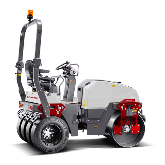
Introduction Introduction The machine Dynapac CC1300C is a self-propelled vibratory combi roller in 4 metric tonnes class featuring a 1300 mm (51 in) wide drum and 1280 mm (50 in.) wide wheels. The machine is equipped with drive and brakes both front and rear and vibrations on front drum. -
Page 12: General
Introduction Read the entire manual before starting the Read the entire manual before starting the machine and before carrying out any machine and before carrying out any maintenance. maintenance. Replace immediately the instruction manuals if Replace immediately the instruction manuals if lost, damaged or unreadable. -
Page 13: Ce Marking And Declaration Of Conformity
Introduction Check the ground under the machine. Leakages are more easily detected on the ground than on the machine itself. THINK ENVIRONMENT ! Do not release oil, THINK ENVIRONMENT ! Do not release oil, fuel and other environmentally hazardous fuel and other environmentally hazardous substances into the environment. - Page 14 Introduction 4812162101_D.pdf 2021-12-14...
-
Page 15: Safety - General Instructions
Safety - General instructions Safety - General instructions (Also read the safety manual) • • The operator must be familiar with the contents of the OPERATION section The operator must be familiar with the contents of the OPERATION section before starting the roller. before starting the roller. - Page 16 Safety - General instructions • • Hearing protection is recommended if the noise level exceeds 80 dB(A). The Hearing protection is recommended if the noise level exceeds 80 dB(A). The noise level can vary depending on the equipment on the machine and the noise level can vary depending on the equipment on the machine and the surface the machine is being used on.
-
Page 17: Safety - When Operating
Safety - when operating Safety - when operating Prevent persons from entering or remaining in Prevent persons from entering or remaining in the risk zone, i.e. a distance of at least 7 m (23 the risk zone, i.e. a distance of at least 7 m (23 ft) in all directions from operating machines. -
Page 18: Driving Near Edges
Safety - when operating Driving near edges Never operate with the drum outside the edge, the Never operate with the drum outside the edge, the substrate might not have full bearing strength or substrate might not have full bearing strength or the edge is close to a slope. -
Page 19: Special Instructions
Special instructions Special instructions Standard lubricants and other recommended oils and fluids Before leaving the factory, the systems and components are filled with the oils and fluids specified in the lubricant specification. These are suitable for ambient temperatures in the range -15°C to +40°C (5°F - 105°F). -
Page 20: Fire Fighting
Special instructions Never aim the water jet directly at the fuel tank Never aim the water jet directly at the fuel tank cap, or into exhaust pipe. This is particularly cap, or into exhaust pipe. This is particularly important when using a high-pressure cleaner. important when using a high-pressure cleaner. -
Page 21: Jump Starting
Special instructions Jump starting Do not connect the negative cable to the Do not connect the negative cable to the negative terminal on the dead battery. A spark negative terminal on the dead battery. A spark can ignite the oxy-hydrogen gas formed can ignite the oxy-hydrogen gas formed around the battery. - Page 22 Special instructions 4812162101_D.pdf 2021-12-14...
-
Page 23: Technical Specifications
Technical specifications Technical specifications Vibrations - Operator station (ISO 2631) The vibration levels are measured in accordance with the operational cycle described in The vibration levels are measured in accordance with the operational cycle described in EU directive 2000/14/EC on machines equipped for the EU market, with vibration switched EU directive 2000/14/EC on machines equipped for the EU market, with vibration switched on, on soft polymer material and with the operator’s seat in the transport position. -
Page 24: Dimensions, Top View
Technical specifications Dimensions, top view Dimensions Dimensions Machine width Machine width 1450 1450 B (Without B (Without Machine width Machine width 1400 1400 ROPS) ROPS) Turning radius, outer Turning radius, outer 4240 4240 Turning radius, inner Turning radius, inner 2940 2940 Wheel width Wheel width... -
Page 25: Dimensions, Side View
Technical specifications Dimensions, side view Dimensions Dimensions Wheel base Wheel base 1925 1925 Diameter, drum Diameter, drum Height, with ROPS Height, with ROPS 2750 2750 Height, without ROPS Height, without ROPS 1910 1910 Length Length 2725 2725 Thickness, drum shell Thickness, drum shell 2021-12-14 4812162101_D.pdf... -
Page 26: Weights And Volumes
Technical specifications Weights and volumes Weights Weights Weight CECE, Standard Weight CECE, Standard 3750 kg 3750 kg 8,270 lbs 8,270 lbs equipped roller equipped roller Fluid volumes Fluid volumes Fuel tank Fuel tank 50 liter 50 liter 52.9 qts 52.9 qts Emulsions tank Emulsions tank 40 liter... -
Page 27: Co 2 -Emission
Technical specifications -emission -emissions measured according to applicable test cycle in Regulation (EU) 2016/1628. Manufacturer/Model Manufacturer/Model Test-cycle Test-cycle -emission -emission (g/kWh) (g/kWh) Kubota D1803-CR-T Kubota D1803-CR-T Stage V Stage V NRTC NRTC 798.1 798.1 Kubota D1803-CR-T Kubota D1803-CR-T Stage V Stage V NRSC NRSC... -
Page 28: Tightening Torque
Technical specifications Tightening torque Tightening torque in Nm for oiled or dry bolts tightened with a torque wrench. Metric coarse screw thread, bright galvanized (fzb): STRENGTH CLASS: 8.8, Oiled 8.8, Oiled 8.8, Dry 8.8, Dry 10.9, Oiled 10.9, Oiled 10.9, Dry 10.9, Dry 12.9, Oiled 12.9, Oiled... -
Page 29: Rops - Bolts
Technical specifications ROPS-bolts which are to be torque tightened ROPS-bolts which are to be torque tightened must be dry. must be dry. ROPS - bolts Bolt dimensions : Bolt dimensions : M16 (PN 4700902889) M16 (PN 4700902889) Strength class : Strength class : 10.9 10.9... - Page 30 Technical specifications 4812162101_D.pdf 2021-12-14...
-
Page 31: Machine Description
Machine description Machine description Diesel engine The machine is equipped with a water-cooled, straight three cylinder, four-stroke, turbocharged diesel engine. Electrical system The machine has the following control units (ECU, Electronic Control Unit) and electronic units. • Main ECU (for the machine) Propulsion system/Transmission The propulsion system is a hydrostatic system with a hydraulic pump supplying three motors connected in... -
Page 32: Identification
Machine description determines whether the modification could result in the approval according to the ROPS standards becoming invalid. Identification Product identification number on the frame The machine PIN (product identification number) (1) is punched on the right edge of the front frame. Fig. -
Page 33: Machine Plate
Machine description Machine plate The machine type plate (1) is affixed on the left front edge of the operator's platform. The plate specifies the manufacturer's name and address, the type of machine, the PIN number (serial number), service weight, engine power and year of manufacture. - Page 34 Machine description 4812162101_D.pdf 2021-12-14...
-
Page 35: Location - Decals
Machine description Location - decals Fig. Location, decals and signs Warning, Crush zone Warning, Crush zone 4700903422 4700903422 Lifting point Lifting point 4700357587 4700357587 Warning, Rotating engine Warning, Rotating engine 4700903423 4700903423 Hydraulic fluid Hydraulic fluid 4700272372 4700272372 components components Bio-Hydraulic oil Bio-Hydraulic oil 4700792772... -
Page 36: Location - Decals, California
Machine description Location - decals, CALIFORNIA Proposition 65 Warning, CALIFORNIA Warning, CALIFORNIA 4812129673 4812129673 Proposition 65 Proposition 65 Fig. Location Safety decals Always make sure that all safety decals are completely legible, and remove dirt or order new decals if they have become illegible. - Page 37 Machine description 4700903459 Warning - Instruction manual The operator must read the safety, operation and maintenance instructions before operating the machine. 4700908229 Warning - Risk of crushing The articulation must be locked when lifting. Read the instruction manual. 4700791642 Warning - Starting gas Starting gas is not to be used.
- Page 38 Machine description 4812129673 Warning CALIFORNIA - Proposition 65 4812162101_D.pdf 2021-12-14...
-
Page 39: Info Decals
Machine description Info decals Noise power level Noise power level Diesel fuel Diesel fuel Lifting point Lifting point Hoisting plate Hoisting plate Handbook compartment Handbook compartment Master switch Master switch Hydraulic fluid Hydraulic fluid Hydraulic fluid level Hydraulic fluid level Securing point Securing point Biological hydraulic fluid,... -
Page 40: Instruments/Controls
Machine description Instruments/Controls Locations - Instruments and controls Fig. Instruments and control panel Manual/automatic sprinkler, drum Manual/automatic sprinkler, drum Low fuel level Low fuel level Sprinkler timer Sprinkler timer Oil pressure, engine Oil pressure, engine Driving lights Driving lights Parking brake lamp Parking brake lamp Working lights Working lights... -
Page 41: Locations - Control Panel And Controls
Machine description Locations - Control panel and controls Fig. Operator position Fig. Operator's station Starter switch Starter switch Emergency stop Emergency stop Vibration On/Off Vibration On/Off Handbook compartment Handbook compartment Forward/reverse lever Forward/reverse lever Seat switch Seat switch Fuse box Fuse box Instrument cover Instrument cover... -
Page 42: Function Description
Machine description Function description Designation Designation Symbol Symbol Function Function Starter switch Starter switch Positions 1-2: Shut off position, key can be removed. Positions 1-2: Shut off position, key can be removed. Position 3a: All instruments and electric controls are Position 3a: All instruments and electric controls are supplied with power. - Page 43 Machine description Designation Designation Symbol Symbol Function Function Driving lights, switch (Optional) Driving lights, switch (Optional) Upper position = Traffic lighting goes on Upper position = Traffic lighting goes on Intermediate position = Lighting switched off Intermediate position = Lighting switched off Lower position = Parking light goes on Lower position = Parking light goes on Working lights, switch...
- Page 44 Machine description Designation Designation Symbol Symbol Function Function Warning lamp, parking brake Warning lamp, parking brake The lamp lights when the parking brake is activated. The lamp lights when the parking brake is activated. Fuel level Fuel level Shows the fuel level in the diesel tank. Shows the fuel level in the diesel tank.
-
Page 45: Electrical System
Machine description Electrical system Fuses on machine equipped with Sauer-Danfoss ECU The figure shows the position of the fuses. The table below gives fuse amperage and function. All fuses are flat pin fuses. Fig. Fuse boxes 1. Upper 2. Lower Fuse box, Upper Fuse box, Upper Fuse box, Lower... -
Page 46: Fuses On Machine Equipped With Hy-Ttc 71 Ecu
Machine description Fuses on machine equipped with HY-TTC 71 The figure shows the position of the fuses. The table below gives fuse amperage and function. All fuses are flat pin fuses. Fig. Fuse boxes 1. Upper 2. Lower Fuse box, Upper Fuse box, Upper Fuse box, Lower Fuse box, Lower... -
Page 47: Fuses At Battery Master Disconnect Switch
Machine description Fuses at battery master disconnect switch The figure shows the position of the fuses. The table below gives fuse amperage and function. All fuses are flat pin fuses. 1. F3 Ignition key 1. F3 Ignition key 2. F4 Starter relay 2. - Page 48 Machine description 4812162101_D.pdf 2021-12-14...
-
Page 49: Operation
Operation Operation Before starting Master switch - Switching on Remember to carry out daily maintenance. See the maintenance instructions. The battery disconnector is on the left side in the engine compartment. Turn the key (1) to switched on position. The roller is now supplied with power. -
Page 50: Driver Seat (Option) - Adjustment
Operation Driver seat (Option) - Adjustment Adjust the operator’s seat so that the position is comfortable and so that the controls are within easy reach. The seat can be adjusted as follows. - Length adjustment (1) - Weight adjustment (2) - Back support angle (3) Fig. - Page 51 Operation Instruments and lamps - Checking Make sure that the emegency stop is pulled out Make sure that the emegency stop is pulled out and the parking brake is activated. When the and the parking brake is activated. When the forward/reverse lever is in neutral, the automatic forward/reverse lever is in neutral, the automatic brake function is engaged.
-
Page 52: Interlock
Operation Interlock The roller is equipped with Interlock. Roller equipped with Sauer-Danfoss ECU: The diesel engine will switch off after 4 seconds if the operator gets off the seat when going forwards/backwards. If the lever is in neutral when the operator gets off the seat a buzzer will go on until the parking brake button is activated. -
Page 53: Parking Brake - Check
Operation Parking brake - Check Make sure that the parking brake (6) is activated. Make sure that the parking brake (6) is activated. The roller can start to roll when the engine is The roller can start to roll when the engine is started on sloping ground, if the parking brake is started on sloping ground, if the parking brake is not applied. -
Page 54: Starting
Operation Starting Starting the engine Make sure that the emergency stop (3) is pulled out and the parking brake (31) is activated. Set the forward/reverse lever (6) in neutral. The engine can only be started when the lever is in neutral. Set the vibration switch (20) for manual/automatic vibration in (position O). -
Page 55: Driving
Operation Check while warming the engine that the warning lamps for the oil pressure (24) and charging (28) go out. The parking brake lamp (25) will remain on for as long as the parking brake switch is activated. When starting and driving a machine that is cold, When starting and driving a machine that is cold, remember that the hydraulic fluid is also cold and remember that the hydraulic fluid is also cold and... -
Page 56: Interlock/Emergency Stop/Parking Brake - Check
Operation Interlock/Emergency stop/Parking brake - Check The interlock, emergency stop and parking brake must The interlock, emergency stop and parking brake must be checked daily before operating. A function check of be checked daily before operating. A function check of the interlock and emergency stop requires a restart. - Page 57 Operation Regen (regeneration) requires (Parked Regen Requested) (36). This is done by moving up the yellow lock and pressing the switch. The switch will spring back afterwards. The speed of the engine increases and the lamp stops flashing but remains on Parked regen (regeneration) in progress (Parked Regen Requested) 35.
-
Page 58: Vibration
Operation Vibration Manual/Automatic vibration Manual or automatic vibration activation/deactivation is selected using switch (20). In the manual position, the operator must activate the vibration using the switch on underside of the forward/reverse lever grip. In the automatic position, vibration is activated when the pre-set speed is reached. -
Page 59: Emergency Braking
Operation Emergency braking Braking is normally activated using the forward/reverse lever (6). The hydrostatic transmission brakes the roller when the lever is moved to the neutral position. There is a brake in each drive motor that acts as an emergency brake during operation. To brake in an emergency situation, push in the To brake in an emergency situation, push in the emergency stop (3), hold the steering wheel firmly... -
Page 60: Parking
Operation Parking Chocking the wheels/drum Never disembark from the machine when the is Never disembark from the machine when the is engine running, unless the parking brake is engine running, unless the parking brake is activated. activated. Make sure that the roller is parked in a safe place Make sure that the roller is parked in a safe place with respect to other road users. -
Page 61: Long-Term Parking
Long-term parking Long-term parking The following instructions should be followed The following instructions should be followed when long term parking (more than one month). when long term parking (more than one month). These measures apply when parking for a period of up to 6 months. -
Page 62: Steering Cylinder, Hinges, Etc
Long-term parking Steering cylinder, hinges, etc. Lubricate the steering joint bearings and both bearings on the steering cylinder with grease (see under the heading 'Every 50 hours of operation'). Grease the steering cylinder piston with conservation grease. Grease the hinges on the doors to the engine compartment and the cab. -
Page 63: Miscellaneous
Miscellaneous Miscellaneous Lifting Locking the articulation Before lifting the roller the steering joint must be Before lifting the roller the steering joint must be locked to prevent it turning. locked to prevent it turning. Turn the steering wheel to the straight ahead position. Switch off the machine and activate the parking brake. -
Page 64: Unlocking The Articulation
Miscellaneous Unlocking the articulation Remember to refit the lock bar (1) in its holder Remember to refit the lock bar (1) in its holder after operation. after operation. Fig. Left side of steering joint 1. Lock bar 2. Lock pin 3. -
Page 65: Release The Brakes
Miscellaneous Release the brakes Activate the parking brake, and stop the engine. Activate the parking brake, and stop the engine. Block the drum with a chock to prevent movement; Block the drum with a chock to prevent movement; the roller can start rolling when the brakes are the roller can start rolling when the brakes are released. -
Page 66: Releasing The Brake, Wheel Motors (Optional)
Miscellaneous Releasing the brake, wheel motors (Optional) Activate the parking brake, and stop the engine. Activate the parking brake, and stop the engine. Block the drum with a chock to prevent movement; Block the drum with a chock to prevent movement; the roller can start rolling when the brakes are the roller can start rolling when the brakes are released. -
Page 67: Towing The Roller
Miscellaneous Towing the roller The roller must be counter-braked during The roller must be counter-braked during towing/recovery. Always use a towbar. There is no towing/recovery. Always use a towbar. There is no braking capacity on the roller now. braking capacity on the roller now. The roller must be towed slowly, max. -
Page 68: Securing Cc1300C For Loading
Miscellaneous Securing CC1300C for loading Securing the CC1300C vibratory roller from Dynapac for transport. Roller loaded in forward direction Direct of travel 1 - 2 1 - 2 = double lashings, i.e. one lashing with two parts secured to two different lashing mounts, = double lashings, i.e. -
Page 69: Retractable Rops (Optional)
Miscellaneous Load carrier Load carrier When loaded, the vibratory roller is centered laterally on the platform (± 5 cm). When loaded, the vibratory roller is centered laterally on the platform (± 5 cm). The parking brake is applied and in good working condition, and the articulated joint lock is The parking brake is applied and in good working condition, and the articulated joint lock is closed. - Page 70 Miscellaneous To retract the ROPS, release the tensioning screw (1), and pull out the pin (2) and stud (3). Do the same on both sides. Lower the ROPS backwards if there is space. Remember to dismantle the rotating warning light Remember to dismantle the rotating warning light before lowering the ROPS.
-
Page 71: Operating Instructions - Summary
Operating instructions - Summary Operating instructions - Summary Follow the SAFETY INSTRUCTIONS specified in the Safety Manual. Follow the SAFETY INSTRUCTIONS specified in the Safety Manual. Make sure that all instructions in the MAINTENANCE section are followed. Make sure that all instructions in the MAINTENANCE section are followed. Turn the master switch to the ON position. - Page 72 Operating instructions - Summary 4812162101_D.pdf 2021-12-14...
-
Page 73: Preventive Maintenance
Preventive maintenance Preventive maintenance Complete maintenance is necessary for the machine to function satisfactorily and at the lowest possible cost. The Maintenance section includes the periodic maintenance that must be carried out on the machine. The recommended maintenance intervals assume that the machine is used in a normal environment and working conditions. - Page 74 Preventive maintenance CALIFORNIA Proposition 65 Decal and location of decal shown in section Machine description. 4812162101_D.pdf 2021-12-14...
-
Page 75: Maintenance - Lubricants And Symbols
Maintenance - Lubricants and symbols Maintenance - Lubricants and symbols Always use high-quality lubricants and the Always use high-quality lubricants and the amounts recommended. Too much grease or amounts recommended. Too much grease or oil can cause overheating, resulting in rapid oil can cause overheating, resulting in rapid wear. -
Page 76: Maintenance Symbols
Maintenance - Lubricants and symbols Maintenance symbols Engine, oil level Engine, oil level Air filter Air filter Engine, oil filter Engine, oil filter Battery Battery Hydraulic reservoir, level Hydraulic reservoir, level Sprinkler Sprinkler Hydraulic fluid, filter Hydraulic fluid, filter Sprinkler water Sprinkler water Drum, oil level Drum, oil level... -
Page 77: Maintenance - Maintenance Schedule
Maintenance - Maintenance schedule Maintenance - Maintenance schedule Service and maintenance points Fig. Service and maintenance points Fuel tank Fuel tank Scrapers Scrapers 17. Filler plugs/Drum 17. Filler plugs/Drum Refueling Refueling 10. Shock absorbers and 10. Shock absorbers and 18. Oil level in drum 18. -
Page 78: Every 10 Hours Of Operation (Daily)
Maintenance - Maintenance schedule Remove all dirt before filling, when checking Remove all dirt before filling, when checking oils and fuel and when lubricating using oil or oils and fuel and when lubricating using oil or grease. grease. The manufacturer’s instructions found in the The manufacturer’s instructions found in the engine manual also apply. -
Page 79: Every 50 Hours Of Operation (Weekly)
Maintenance - Maintenance schedule Every 50 hours of operation (Weekly) See Contents to find the page number of the sections referred to! Pos. Pos. Action Action Comment Comment in fig in fig Check the air cleaner. Check the air cleaner. Replace when necessary Replace when necessary Check that hoses and connections are tight... -
Page 80: Every 500 / 1500 Hours Of Operation
Maintenance - Maintenance schedule Every 500 / 1500 hours of operation See Contents to find the page numbers of the sections referred to! Pos. Pos. Action Action Comment Comment in fig in fig Check the battery Check the battery Change engine oil and oil filter Change engine oil and oil filter Refer also to the Instruction Refer also to the Instruction... -
Page 81: Every 1000 Hours Of Operation
Maintenance - Maintenance schedule Every 1000 hours of operation See Contents to find the page number of the sections referred to! Pos. Pos. Action Action Comment Comment in fig in fig Check the battery Check the battery Change engine oil and oil filter Change engine oil and oil filter Refer also to the Instruction Refer also to the Instruction... -
Page 82: Every 2000 Hours Of Operation
Maintenance - Maintenance schedule Every 2000 hours of operation See Contents to find the page numbers of the sections referred to! Pos. Pos. Action Action Comment Comment in fig in fig Check the battery condition Check the battery condition Change the engine oil and oil filter Change the engine oil and oil filter Refer to the engine manual Refer to the engine manual... -
Page 83: Service - Checklist
Maintenance - Maintenance schedule Service - Checklist 2021-12-14 4812162101_D.pdf... - Page 84 Maintenance - Maintenance schedule 4812162101_D.pdf 2021-12-14...
-
Page 85: Maintenance, 10H
Maintenance, 10h Maintenance, 10h Every 10 hours of operation (Daily) Park the roller on a level surface. Park the roller on a level surface. The engine must be switched off and the The engine must be switched off and the parking brake activated when checking or parking brake activated when checking or adjusting the roller, unless otherwise specified. -
Page 86: Coolers
Maintenance, 10h Coolers Checking - Cleaning Make sure that the air flow through the coolers (1) and (2) is unobstructed. Dirty coolers are blown clean with compressed air or washed clean using a high-pressure water cleaner. Blow air or direct water through the cooler in the opposite direction to that of the cooling air. -
Page 87: Hydraulic Reservoir, Level Check - Filling
Maintenance, 10h Hydraulic reservoir, Level check - Filling Check that the level is between the min and max markings. Top up with hydraulic fluid as per lubricant specifications if level is too low. Fig. Hydraulic fluid tank 1. Sight glass Open the engine hood and unscrew the filler cap, top up with hydraulic fluid (as per lubricant specification) if the level is too low. -
Page 88: Lowering Of Engine Hood
Maintenance, 10h Lowering of engine hood Stand on the left side of the engine hood. Press in the Stand on the left side of the engine hood. Press in the red button (3) and carefully lower the engine hood red button (3) and carefully lower the engine hood until the gas spring (2) goes into the slot. -
Page 89: Fuel Tank - Filling
Maintenance, 10h Fuel tank - Filling Refuel every day before starting to work. Screw off the lockable tank cap (1) and fill diesel fuel to the lower edge of the filler pipe. Stop the diesel engine. Short-circuit (press) the Stop the diesel engine. Short-circuit (press) the filler gun against a non-insulated part of the roller filler gun against a non-insulated part of the roller before refuelling, and against the filler pipe while... -
Page 90: Sprinkler System/Drum Checking - Cleaning
Maintenance, 10h Sprinkler system/Drum Checking - Cleaning Start the sprinkler system and make sure that no nozzles (1) are clogged. If necessary, clean clogged nozzles and the coarse filter located by the water pump; see figures below. The sprinkler system The sprinkler system should be drained if there should be drained if there... -
Page 91: Scrapers, Fixed Checking - Setting
Maintenance, 10h Dismantle the blocked nozzle by hand. Blow the nozzle (2) and fine filter (4) clean with compressed air, or install replacement parts and clean the clogged parts later. Wear protective goggles when working with Wear protective goggles when working with compressed air. -
Page 92: Scrapers, Spring-Action (Optional) Checking - Adjustment
Maintenance, 10h Scrapers, spring-action (Optional) Checking - Adjustment The scrapers must be lifted from the drum during The scrapers must be lifted from the drum during transport. transport. Fig. Spring-action scrapers 1. Scraper blade 2. Adjusting screws Scrapers Check - Adjustment Make sure that the scraper (1) is flush with the tire when compacting asphalt. -
Page 93: Pump System / Tire Check - Cleaning
Maintenance, 10h When cleaning the coarse filter (1), open the cock (2) and loosen the filter housing. Clean the filter and filter housing. Check that the rubber gasket in the filter housing is intact. After inspecting and carrying out any necessary cleaning, start the system and check that it works. -
Page 94: Brakes - Check
Maintenance, 10h Brakes - Check Check operation of the brakes as follows: Check operation of the brakes as follows: Run the roller very slowly forward. Hold the steering wheel firmly and brace yourself for a sudden stop. Press in the emergency stop (3). The roller will stop Figure. -
Page 95: Maintenance - 50H
Maintenance - 50h Maintenance - 50h Every 50 hours of operation (Weekly) Park the roller on a level surface. Park the roller on a level surface. The engine must be switched off and the The engine must be switched off and the parking brake activated when checking or parking brake activated when checking or adjusting the roller, unless otherwise specified. -
Page 96: Air Filter Indicator - Resetting
Maintenance - 50h Release the clips (1), pull off the cover (2), and pull out the main filter (3). Do not remove the backup filter (4). Clean the air cleaner if necessary, see section Air cleaner - Cleaning. When replacing the main filter (3), insert a new filter and refit the air cleaner in the reverse order. -
Page 97: Air Cleaner - Cleaning
Maintenance - 50h Air cleaner - Cleaning Wipe clean the inside of the cover (2) and the filter housing (5). See the previous illustration. Wipe clean on both sides of the outlet Wipe also both surfaces for the outlet pipe; see pipe. -
Page 98: Tires - Tire Pressure
Maintenance - 50h Tires - Tire pressure Check the air pressure with a pressure gauge. Make sure that the tires have the same pressure. Recommended pressure: See Technical Specifications. Fig. Tire 1. Air valve Pre-fuel filter - Draining Unscrew the drain plug (1) at the bottom of the fuel filter. -
Page 99: Maintenance Measures - 250 H
Maintenance measures - 250 h Maintenance measures - 250 h Every 250/750/1250/1750..hours of operation (every 3 months) Park the roller on a level surface. Park the roller on a level surface. The engine must be switched off and the The engine must be switched off and the parking brake activated when checking or parking brake activated when checking or... -
Page 100: Engine Oil And Oil Filter - Change
Maintenance measures - 250 h Engine oil and oil filter - Change Run the engine until it is warm before draining the oil . Switch off the engine and push in the emergency Switch off the engine and push in the emergency stop. -
Page 101: Coolers
Maintenance measures - 250 h Coolers Checking - Cleaning Make sure that the air flow through the coolers (1) and (2) is unobstructed. Dirty coolers are blown clean with compressed air or washed clean using a high-pressure water cleaner. Blow air or direct water through the cooler in the opposite direction to that of the cooling air. - Page 102 Maintenance measures - 250 h 4812162101_D.pdf 2021-12-14...
-
Page 103: Maintenance Measures - 500 H
Maintenance measures - 500 h Maintenance measures - 500 h Every 500/1500..hours of operation (every six months) Park the roller on a level surface. Park the roller on a level surface. The engine must be switched off and the The engine must be switched off and the parking brake activated when checking or parking brake activated when checking or... -
Page 104: Engine Oil And Oil Filter - Change
Maintenance measures - 500 h Engine oil and oil filter - Change Run the engine until it is warm before draining the oil . Switch off the engine and push in the emergency Switch off the engine and push in the emergency stop. -
Page 105: Drum - Oil Level Inspection - Filling
Maintenance measures - 500 h Drum - oil level Inspection - filling Run the roller slowly until the oil plug (1) is aligned with the semicircular recess in the drum suspension. Unscrew the plug and check that the oil level reaches up to the bottom of the hole. -
Page 106: Controls - Lubrication
Maintenance measures - 500 h Controls - Lubrication Lubricate the forward/reverse lever in the engine compartment with a few drops of oil. If the lever gets stiff after a prolonged period of use, remove the cover and lever and lubricate. Fig. -
Page 107: Controls - Lubrication
Maintenance measures - 500 h Controls - Lubrication Lubricate the forward/reverse lever mechanism. Remove the cover/plate (1) by loosening the screws (2) on the top, and lubricate the mechanism under the cover/plate with oil. Fig. Forward/Reverse lever 1. Plate 2. Attachment screws Check - Coolant system Check that all hoses/hose connectors are intact and tight. -
Page 108: Replacing The Fuel Filter
Maintenance measures - 500 h Replacing the fuel filter Place a container underneath to collect fuel that Place a container underneath to collect fuel that runs out when the filter is released. runs out when the filter is released. Screw off the fuel filter (1). The filter is of the disposable type and cannot be cleaned. -
Page 109: Replacing The Pre-Filter
Maintenance measures - 500 h Replacing the pre-filter Activate the parking brake. Switch off the engine and remove the plate on the left side of the frame (at battery disconnector) by releasing the three bolts (3). Release the hose clamps (2) with a screwdriver. Place a container underneath to collect fuel that Place a container underneath to collect fuel that runs out when the filter is released. -
Page 110: Replacing The Diesel Engine's Oil Separator Filter
Maintenance measures - 500 h Replacing the diesel engine’s oil separator filter (applies to 1500h) N.B. The engine must be switched off when changing the filter. Loosen the filter’s bottom cover (2) and remove the filter insert and O-ring (3). Fig. -
Page 111: Maintenance - 1000H
Maintenance - 1000h Maintenance - 1000h Performed after 1000 operating hours (each year) Park the roller on a level surface. Park the roller on a level surface. The engine must be switched off and the The engine must be switched off and the parking brake activated when checking or parking brake activated when checking or adjusting the roller, unless otherwise specified. -
Page 112: Engine Oil And Oil Filter - Change
Maintenance - 1000h Engine oil and oil filter - Change Run the engine until it is warm before draining the oil . Switch off the engine and push in the emergency Switch off the engine and push in the emergency stop. -
Page 113: Drum - Oil Level Inspection - Filling
Maintenance - 1000h Drum - oil level Inspection - filling Run the roller slowly until the oil plug (1) is aligned with the semicircular recess in the drum suspension. Unscrew the plug and check that the oil level reaches up to the bottom of the hole. Top up with new oil if necessary. -
Page 114: Controls - Lubrication
Maintenance - 1000h Controls - Lubrication Lubricate the forward/reverse lever in the engine compartment with a few drops of oil. If the lever gets stiff after a prolonged period of use, remove the cover and lever and lubricate. Fig. Engine compartment 1. -
Page 115: Controls - Lubrication
Maintenance - 1000h Controls - Lubrication Lubricate the forward/reverse lever mechanism. Remove the cover/plate (1) by loosening the screws (2) on the top, and lubricate the mechanism under the cover/plate with oil. Fig. Forward/Reverse lever 1. Plate 2. Attachment screws Check - Coolant system Check that all hoses/hose connectors are intact and tight. -
Page 116: Replacing The Fuel Filter
Maintenance - 1000h Replacing the fuel filter Place a container underneath to collect fuel that Place a container underneath to collect fuel that runs out when the filter is released. runs out when the filter is released. Screw off the fuel filter (1). The filter is of the disposable type and cannot be cleaned. -
Page 117: Replacing The Pre-Filter
Maintenance - 1000h Replacing the pre-filter Activate the parking brake. Switch off the engine and remove the plate on the left side of the frame (at battery disconnector) by releasing the three bolts (3). Release the hose clamps (2) with a screwdriver. Place a container underneath to collect fuel that Place a container underneath to collect fuel that runs out when the filter is released. -
Page 118: Replacing The Hydraulic Oil Filter
Maintenance - 1000h Replacing the hydraulic oil filter Unscrew the retaining screws (1) on each side of the roller. Remove the protective cover (2). Fig. Engine compartment 1. Retaining screws 2. Protective cover Loosen the red cap (3) and pull up the filter insert (4). Refit the red cap temporarily to prevent dust and dirt getting into the tank. - Page 119 Maintenance - 1000h Release the filter insert (4) from the handle (5). Remove the filter (4) and hand in to an Remove the filter (4) and hand in to an environment-friendly waste disposal station. This environment-friendly waste disposal station. This is a disposable filter and cannot be cleaned.
- Page 120 Maintenance - 1000h 4812162101_D.pdf 2021-12-14...
-
Page 121: Maintenance - 2000H
Maintenance - 2000h Maintenance - 2000h Performed after 2000 operating hours (every two years) Park the roller on a level surface. Park the roller on a level surface. The engine must be switched off and the The engine must be switched off and the parking brake activated when checking or parking brake activated when checking or adjusting the roller, unless otherwise specified. -
Page 122: Engine Oil And Oil Filter - Change
Maintenance - 2000h Engine oil and oil filter - Change Run the engine until it is warm before draining the oil . Switch off the engine and push in the emergency Switch off the engine and push in the emergency stop. -
Page 123: Drum - Oil Level Inspection - Filling
Maintenance - 2000h Drum - oil level Inspection - filling Run the roller slowly until the oil plug (1) is aligned with the semicircular recess in the drum suspension. Unscrew the plug and check that the oil level reaches up to the bottom of the hole. Top up with new oil if necessary. -
Page 124: Controls - Lubrication
Maintenance - 2000h Controls - Lubrication Lubricate the forward/reverse lever in the engine compartment with a few drops of oil. If the lever gets stiff after a prolonged period of use, remove the cover and lever and lubricate. Fig. Engine compartment 1. -
Page 125: Controls - Lubrication
Maintenance - 2000h Controls - Lubrication Lubricate the forward/reverse lever mechanism. Remove the cover/plate (1) by loosening the screws (2) on the top, and lubricate the mechanism under the cover/plate with oil. Fig. Forward/Reverse lever 1. Plate 2. Attachment screws Check - Coolant system Check that all hoses/hose connectors are intact and tight. -
Page 126: Replacing The Hydraulic Oil Filter
Maintenance - 2000h Replacing the hydraulic oil filter Unscrew the retaining screws (1) on each side of the roller. Remove the protective cover (2). Fig. Engine compartment 1. Retaining screws 2. Protective cover Loosen the red cap (3) and pull up the filter insert (4). Refit the red cap temporarily to prevent dust and dirt getting into the tank. -
Page 127: Hydraulic Fluid Reservoir - Draining
Maintenance - 2000h Release the filter insert (4) from the handle (5). Remove the filter (4) and hand in to an Remove the filter (4) and hand in to an environment-friendly waste disposal station. This environment-friendly waste disposal station. This is a disposable filter and cannot be cleaned. -
Page 128: Hydraulic Tank - Changing The Fluid
Maintenance - 2000h Hydraulic tank - Changing the fluid Risk of burn injuries when draining hot oil. Protect Risk of burn injuries when draining hot oil. Protect your hands. your hands. Place a container under the plug. It should hold at Place a container under the plug. -
Page 129: Replacing The Pre-Filter
Maintenance - 2000h Replacing the pre-filter Activate the parking brake. Switch off the engine and remove the plate on the left side of the frame (at battery disconnector) by releasing the three bolts (3). Release the hose clamps (2) with a screwdriver. Place a container underneath to collect fuel that Place a container underneath to collect fuel that runs out when the filter is released. -
Page 130: Replacing The Fuel Filter
Maintenance - 2000h Replacing the fuel filter Place a container underneath to collect fuel that Place a container underneath to collect fuel that runs out when the filter is released. runs out when the filter is released. Screw off the fuel filter (1). The filter is of the disposable type and cannot be cleaned. -
Page 131: Water Tank - Draining
Maintenance - 2000h Water tank - Draining Remember that there is a risk of freezing during Remember that there is a risk of freezing during the winter. Empty the tank, pump and lines. the winter. Empty the tank, pump and lines. The easiest way to empty the water tank is to open the drain cock on the water filter (1). -
Page 132: Water Tank - Cleaning
Maintenance - 2000h Water tank - Cleaning Clean the tanks with water and a suitable detergent for plastic surfaces. Refit the filter housing or the drain plug (1). Fill with water and check for leaks. The water tanks are made of plastic The water tanks are made of plastic (polyethylene) and are recyclable. -
Page 133: Fuel Tank - Cleaning
Maintenance - 2000h Fuel tank - Cleaning It is easiest to clean the tank when it is almost empty. Pump out any bottom sediment using a suitable Pump out any bottom sediment using a suitable pump, such as an oil drain pump. Save the oil in pump, such as an oil drain pump. - Page 134 Dynapac Compaction Equipment AB Box 504, SE 371 23 Karlskrona, Sweden www.dynapac.com...
Need help?
Do you have a question about the DYNAPAC CC1300C and is the answer not in the manual?
Questions and answers