Table of Contents
Advertisement
Quick Links
Advertisement
Table of Contents

Related Manuals for Fayat Group Dynapac CP2100


Summary of Contents for Fayat Group Dynapac CP2100
- Page 1 Instruction Manual 4812314580EN Operation and Maintenance Pneumatic Tire Roller CP2100 / CP2100W Diesel Engine Cummins QSB 3.3 – Tier III Cummins QSF 3.8 - Tier IV Serial number 10000511CLC009619 - 10000516VLC009620 - It is reserved the right to make any changes Printed in Brazil...
-
Page 4: Table Of Contents
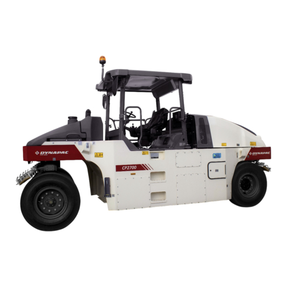
Introduction TABLE OF CONTENTS OPERATION Page Safety – Option items ......................8 Technical Specifications ..................... 10 Technical specifications -Dimensions ................12 Safety decals - description and location ................14 Identification plates ......................19 Instruments/controls ......................21 Instruments and Controls - Cab ..................38 A/C –... - Page 7 Introduction Introduction Dynapac CP2100 / CP2100W Dynapac CP2100 is a 21 tones rubber wheel roller, with 5,905 ft (1,800 m) width. CP2100 is also available on the wide base version (CP2100W), with larger tires and 7,480 ft (2,280 m) width.
- Page 8 Introduction General Information This manual contains instructions to operate and perform the maintenance of the machine. The machine's maintenance shall be made correctly in order to obtain the maximum performance and the equipment shall also be kept clean, so leakage, loosen bolts and connections can be found as soon as possible.
- Page 9 Introduction 2020-01-06 4812314580EN...
- Page 10 Safety - General instructions Safety - General instructions (you must also read the Safety Manual) Read and understand this Manual before starting and operating the machine. The operator must be familiar with the equipment contents before operating it. 2. Observe and follow all the Maintenance Section instructions. 3.
- Page 11 Safety - General instructions 19. For your own protection, always wear: - Helmet; - Working boots with steel toecaps; - Ear protectors; - Reflecting clothing; - Working gloves. 20. If there is a cab in the machine, operate it always with the doors closed and with the seat belt.
- Page 12 Safety Safety - When operating Avoid people entering at the danger area, that is, at a distance of at least 23 ft (7 m) in all the directions from the machine operating. The operator can allow one person to be at the danger area, but in this case, care must be taken and the machine can only be operated when this person is in a visible place or with clear indication of where he/she is.
- Page 13 Safety Transport on steep ground During the transport on steep ground (slope >5%), be careful to not exceed the roller's maximum speed. Take your foot off the throttle pedal and use the engine brake system. Also use the main brake if the speed keeps increasing. Selecting the low speed will increase the engine brake system efficacy and also the life of the braking system.
-
Page 14: Safety - Option Items
Safety - Option items Safety – Option items Air conditioning The system contains pressurized refrigerant. It is forbidden to release refrigerant to the atmosphere. The maintenance of the air conditioning system shall be carried out only by trained people and with the proper tools and equipment. - Page 15 Safety - Option items Working lights - Xenon CAUTION! High voltage! The working lights are Xenon type and have a high voltage auxiliary source of power. Any maintenance on the lighting system shall be performed by authorized technicians and the main power source shall be off. CAUTION! Environmentally hazardous waste! The xenon lamps of the working lights contain mercury (Hg).
-
Page 16: Technical Specifications
Safety - Option items Technical Specifications Vibrations – Operator station (ISO 2631) The vibration levels are measured according to the operational cycle described in the EU directive 2000/14/EC on machines equipped for the EU market with the operator’s seat in the transport position. - Page 17 Technical specifications 2020-01-06 4812314580EN...
-
Page 18: Technical Specifications -Dimensions
Technical specifications Technical specifications -Dimensions Dimensions Dimensions inches A – Between axles 4.000 B – Total width 2.032 – Height with attachment 3.344 – Total height 2.990 K – Height from the ground L – Total length 5.180 4812314580EN 2020-01-06... - Page 19 Technical specifications CP2100 Dimension Millimeter Inch R – Outer radius 7994 r – Inner radius 5249 x – Tire width 11,8 CP2100W Dimensions Millimeter Inch R – Outer radius 8164 r – Inner radius 5022 x – Tire width 14,1 Dimension Degree O –...
-
Page 20: Safety Decals - Description And Location
Safety decals - description and location Safety decals - description and location 15, 16 15, 16 2, 3 4812314580EN 2020-01-06... - Page 21 Safety decals - description and location Safety decals - Description and location (cont.) Always make sure that all the safety decals are completely legible and remove the dirt or request for new ones if they are illegible. Use the part number indicated on each decal.
- Page 22 Safety decals - description and location Safety decals - Description and location (cont.) Emergency exit - Cab. Fire extinguisher Hoisting plate Tire pressure Diesel oil Securing point Lifting point Hydraulic oil Bio-hydraulic oil (option) 4812314580EN 2020-01-06...
- Page 23 Safety decals - description and location Safety decals - Description and location (cont.) Handbook compartment Master switch Battery voltage Sound power level Water tank Hydraulic oil level 2020-01-06 4812314580EN...
- Page 24 Safety decals - description and location 4812314580EN 2020-01-06...
-
Page 25: Identification Plates
Identification plates Identification plates Machine plate. The machine plate (1) is on the top step, on the left side of the operator's platform. It specifies the manufacturer's name, the type of the machine, the serial number, the service weight, the engine power and the manufacturing year (machines delivered outside EU do not present CE marking and in some cases they also do not present the manufacturing year). - Page 26 Identification plates Explanation of the 17PIN (Product Identification 00123 123456 Number) A – Manufacturer's code (100 = Dynapac) B – Family/model code (00501 = CP2100) C – Check code D – Year of manufacturing (E=2014, F=2015...) E – Production's unit code (B = Sorocaba, Brazil) F –...
-
Page 27: Instruments/Controls
Instruments/controls Instruments/controls Control panel, side panel command keyboard. Fig. Control panel, side panel and command keyboard. 1. Ignition key 2. Forward/reverse lever 3. Command keyboard 4. Direction lights (OPTION) 5. Warning lights 6. High beam lights (OPTION) 7. "+" increase in the tire pressure (OPTION) 8. - Page 28 Instruments/controls Pedals The roller has two pedals: 1. Throttle pedal 2. Brake pedal Fig. – Pedals Steering column multiple switch (option) Switch functions: 1. Forward/reverse lever 2. Central warning lights 3. Direction lights Fig. - Steering column multiple switch (option) 4812314580EN 2020-01-06...
- Page 29 Instrument/controls - Description and function 2020-01-06 4812314580EN...
- Page 30 Instrument/controls - Description and function Instrument/controls - Description and function DESIGNATION SYMBOL FUNCTION Ignition key The electric circuit is off. All instruments and electric controls are on. The starter is activated. To start the machine, the lever shall be in Forward/reverse lever the "neutral"...
- Page 31 Instrument/controls - Description and function Instrument/controls - Description and function (cont.) DESIGNATION SYMBOL FUNCTION "-" decrease of the sprinkler The sprinkling frequency decreases each interval (timer) time the water volume on the wheels is also decreased. Working lights Press to turn on/off all the working lights. Horn switch Press to sound the horn.
- Page 32 Instrument/controls - Description and function Instrument/controls - Description and function (cont.) DESIGNATION SYMBOL FUNCTION It shows the engine and transmission Control panel functions. Refer to the Section: "Before Starting". Function buttons (5) Brake test pedal Press it to test the brakes. Parking brake When it is pressed, the parking brake is activated.
- Page 33 Instrument/controls - Description and function Control panel – General description When the ignition key is in the position "I", the start screen is visible on the display. It remains activated for a few seconds then it switches to the status screen. Fig.
- Page 34 Instrument/controls - Description and function Control panel – General description (cont.) A menu field is shown by pressing one of the selection buttons. It is visible for a short time, then it fades out if any selection is made. A menu field appears again by pressing one of the selection buttons (1).
- Page 35 Instrument/controls - Description and function Control panel - Alarms It is also possible to refer to a menu with the asphalt temperature when the asphalt temperature gauge (option) is installed. Set the upper and lower temperature limits with the function keys. If the asphalt effective temperature is outside the limits, the value shown in the top of the main screen starts to flash.
- Page 36 Instrument/controls - Description and function 4812314580EN 2020-01-06...
- Page 37 Instrument/controls - Description and function Control panel – Alarms (cont.) SYMBOL DESCRIPTION FUNCTION If the symbol appears with the engine in Warning symbol, hydraulic oil filter. maximum rpm, it shall be necessary to replace the hydraulic oil. If the symbol appears with the engine in Warning symbol, air filter.
- Page 38 Instrument/controls - Description and function Fail list Byte . Bit Description Action Hydraulic Filter Air Filter No Charging Low Fuel Low Spr. Water Engine Temp Hydraulic Temp (Temperatura hidráulica) Battery tension will be monitored. < 9 V ou > 36V = SAFE MODE Safe Mode <...
- Page 39 Instrument/controls - Description and function 2020-01-06 4812314580EN...
- Page 40 Instruments/controls - Cab Control panel – Alarms (cont.) Alarms received are stored/logged and can be seen by selecting Display Alarms. “ENGINE ALARM” Stored/logged engine alarms. “MACHINE ALARM” Stored/logged machine alarms. They come from other systems on the machine. 4812314580EN 2020-01-06...
- Page 41 Instrument/controls - Description and function “USER SETTINGS” Users can change lighting settings, choose between Metric or Imperial system and set warning sounds on/off. Adjustment of light and contrast settings on the display, including brightness of the panel light. Operator help when starting 2020-01-06 4812314580EN...
- Page 42 Emergency procedures When trying to turn on the machine without having set up to three necessary conditions to do so, the missing ones are shown in the display. The missing conditions must be set before turning on the machine. Conditions that must be set: - The parking brake shall be activated.
- Page 43 Emergency procedures Regeneration system (Emission Control) This equipment has a system of emission control and need special care during the operation. This system has a particulate filter (DPF) which accumulates pollutants throughout the operation and must go through a regeneration process that happens automatically, to eliminate the accumulated material.
-
Page 44: Instruments And Controls - Cab
Emergency procedures When the high level (High) contamination is achieved, the equipment will be turned off and the engine red alert will be triggered. Under these conditions, we recommend stop the machine immediately and let it perform the regeneration completely. Fig. - Page 45 Instruments/controls - Cab Radio/CD player (option) Radio/ Option 2020-01-06 4812314580EN...
- Page 46 Emergency procedures 4812314580EN 2020-01-06...
- Page 47 Instruments/controls - Cab Instruments and controls - Cab DESIGNATION SYMBOL FUNCTION Automatic Climate Control Air conditioning automatic control (see A/C operation for detail). Front wiper, intermittent Intermittent function for front wiper. Front wiper switch Press to operate the front windshield wiper.
-
Page 48: A/C - System Operation
Instruments/controls - Cab A/C – System operation Power/Enter By feeding the panel with 24VDC, the screen will be on, indicating that the product is in standby mode. Press to turn on the A/C, it will show the software version and then the temperature. - Page 49 Instruments/controls - Cab Ventilation The controller has two ventilation modes: manual and automatic ventilation. Manual ventilation The manual ventilation has three speeds. When some function (cooling, heating or automatic mode) is active, the ventilation function is always on. To change the fan speed, press the key (Ventilation mode) and after set the desired speed with the keys After press the key...
- Page 50 Instruments/controls - Cab 4812314580EN 2020-01-06...
-
Page 51: Operation - Before Starting
Operation - Before starting Operation - Before starting Daily maintenance Before starting your work shift and operating equipment, make sure daily maintenance was carried out. For further information, refer to the maintenance section in this manual. Master switch Check if the master switch is on. The master switch is located in the electric device compartment (1) on the right side of the machine. - Page 52 Operation - Before starting Standard operator's seat - adjustment Adjust the operator's seat so all the controls are within easy reach and the machine operation is comfortable. (1) Length adjustment. (2) Weight adjustment. (3) Back support adjustment. (4) Seat belt. ALWAYS make sure the seat is locked before starting the operation.
- Page 53 Operation - Before starting View Before starting the engine, make sure that the view around the machine is unobstructed. All the cab windows shall be clean and the rear view mirrors adjusted for a good rear view. Operator position If a ROPS (Roll Over Protective Structure) or a cab is fitted to the roller, always use the seat belt (1) and wear a protective helmet.
- Page 54 Operation Starting Screen - Control Sit down for all operations. Turn the ignition key (1) to the position I and the initial screen is shown in the Control panel (2). Fig.– Side panel 1. Ignition key 2. Control Panel Check if the voltmeter (3) appoints at least 24 volt and if the fuel (4) and water (5) levels show a percentage value.
- Page 55 Operation Starting the engine Make sure the emergency stop system (2) is off (upper position) and the parking brake is on. The forward/reverse lever (1) shall be in the neutral position. The Diesel engine cannot be started if the lever is not in this position.
-
Page 56: Display And Button Set
Operation Display and button set The parking brake symbol is shown when the parking brake is activated. = Low speed. = Automatic water control (AWC). The sprinkling is activated when the forward/backward lever is in the neutral position. = Tire pressure. = Sprinkler activation for edge cutter. - Page 57 Operation Operating the roller Under no circumstances the machine shall be operated away from the ground. The operator shall be seated inside the machine during the operation. Make sure the areas at the front and behind the machine are free. 1.
- Page 58 Operation Edge cutter (option) To activate the edge cutter, the machine must be in low speed. When the side panel button (1) is pressed with the machine in low speed, a hydraulic piston lowers down the edge cutter to the ground. The tool can also be lifted if the machine is in the transport position.
- Page 59 Operation Coconut mats (option) To apply the coconut mats (1) on the wheels, follow the instructions below: - Hold and lift the handle in the middle of the scraper holder (2). - Make sure the lock pin (4) releases properly from the locking hook (3) and allow the scraper to rest against the tires in the working position.
- Page 60 Operation Ballast box Fig.– Ballast box cover Water and wet sand ballast 1. Top covers 2. Side lower covers Remove the top covers (1) and side upper covers (3) and fill 3. Side upper covers 4. Draining plugs with water and sand through this opening. Keep the side lower covers (2) closed during the water filling.
- Page 61 Operation Removable steel ballasts The CP2100/CP2100W roller uses an innovative and patented system of steel ballasts, which can be removed and installed easily and quickly: 1. With the ballast box drained (without water and/or sand), remove four side covers (1) from the ballast box. 2.
- Page 62 Operation Ground pressure (driving) The tire contact surface can be changed by means of tire pressure. The high pressure on the tires provides a smaller contact surface (1) and the low pressure on the tire provides a larger contact surface (2). The contact surface with the ground is very important for the compaction result.
- Page 63 Operation Low tire pressure – 240 kPa (34,8 PSI) The lower the tires pressure, the lower the pressure on the contact surface, due to the larger surface area. Fig. - Low ground pressure, larger contact area Normal tire pressure – 480 kPa (69,6 PSI) Used for degradation session.
- Page 64 Operation Interlock/Emergency Stop/Parking Brake The interlock, emergency stop and parking brake shall be checked daily before starting the machine. To check if the emergency stop and interlock are working correctly, it is necessary to turn on and off the machine. To check if the Interlock works correctly, the operator shall rise from the seat with the roller moving forwards and backwards (perform the...
- Page 65 Operation Emergency braking The brake pedal is normally used to brake. For emergency braking, press the emergency stop button (1), hold the steering wheel and be ready for a sudden stop. The engine stops. The Diesel engine will be turned off and it must be turned on again, if necessary.
- Page 66 Operation Chocking the wheels Never leave the roller and let it with the engine running unless the parking brake is activated. Make sure the machine is parked in a safe area, without traffic. Chock the wheels when parking on slopes. In extremely cold weather, some components may freeze.
- Page 67 Operation 2020-01-06 4812314580EN...
- Page 68 Parking Long-term storage For long-term storage (more than a month) follow the instructions below: These measures are valid for storage for a period of up to 6 months. Before starting the machine again, the points stated below shall be performed before parking and store the roller. Wash the machine and touch up the painting finishing to prevent rusting.
- Page 69 Parking Hydraulic oil reservoir Fill the hydraulic reservoir until the uppermost level mark (refer to the section "Every 10 Hours of Operation"). Tires Make sure the tires pressure is at least 200 kPa (29 PSI). Place supports under the chassis so that the tires are not overloaded.
-
Page 70: Lifting
Towing Lifting Lifting the roller Make sure the front wheels are parallel with the frame before lifting the roller. Make sure the hooks are safely placed in the lifting eyes. The equipment shall only be lifted by the proper lifting eyes. Always use cables and steel chains according to the safety norms and make sure there are no worn components and that parts are not damaged during... -
Page 71: Towing
Towing Towing Short distance towing with the engine running The roller can be moved up to 984 feet (300 meters), according to the following instructions: To tow the machine, use the same lifting points. Park the roller on a flat and safe place. If necessary, chock the tires. - Page 72 Towing Short distance towing with engine inoperative As a safety measure, chock the wheels to prevent the machine to move when the brakes are hydraulically disengaged. The roller can be moved up to 984 feet (300 meters), according to the following instructions: 1.
- Page 73 Towing Towing the roller When towing, the roller shall be braked by the towing vehicle. Always use a towing bar, because the machine cannot brake. The roller must be towed slowly and must not be moved in a speed higher than 5 km/h and over 984 feet (300 meters).
-
Page 74: Transport
Transport Transport Preparing the roller for transport Apply the parking brake and make sure the machine is in the neutral position, that is, that the tires are pointing forwards. Chock (1) the tires in an angle of 37º and at a minimum height of 9,9 inches (25 cm). - Page 75 Transport 2020-01-06 4812314580EN...
-
Page 76: Operation Instructions - Overview
Operation instructions - Overview Operation instructions - Overview Follow the safety instructions specified in the Safety Manual. ● Make sure all the MAINTENANCE INSTRUCTIONS were carried out. further information, refer Maintenance section in this manual. ● Turn on the battery switch. ●... - Page 77 Operation instructions - Overview 2020-01-06 4812314580EN...
-
Page 78: Preventive Maintenance
Operation instructions - Overview Preventive maintenance Introduction It is necessary to carry out a complete maintenance so the machine can work satisfactorily and at the lowest possible costs. The Maintenance section includes the periodic maintenance that shall be carried out on the machine. The recommended maintenance intervals assume that the machine is being used in a normal environment and working conditions. - Page 79 Preventive maintenance 2020-01-06 4812314580EN...
-
Page 80: Preventive Maintenance - Symbols And Lubricants
Preventive maintenance - Symbols and lubricants Preventive maintenance - Symbols and lubricants Always use high quality lubricants and in the amounts required. Too much grease or lubricant oil can cause overheating and premature wear. ENGINE OIL ENGINE TIER III Shell Rimula R4 L 15W-40 or equivalent. Room temperature: 5 F to 122 F (-15ºC to 50ºC) ENGINE TIER IV... - Page 81 Preventive maintenance - Symbols and lubricants Engine, oil level Engine, oil filter Hydraulic fluid, level Air filter Hydraulic fluid, filter Transmission, oil level Fuel filter Battery Coolant level 2020-01-06 4812314580EN...
- Page 82 Preventive maintenance - Symbols and lubricants Lubricating oil Air pressure Sprinkler Sprinkler water Recycling 4812314580EN 2020-01-06...
-
Page 83: Specifications
Specifications Specifications WEIGHTS Operational weight with ROPS and series 9,450 kg equipment (20,828 lb) Weight without ballast 9,050 kg (19,947 lb) Weight with ballast, wet sand 15,810 kg (34,846 lb) Weight with maximum ballast 21,000 kg (46,285 lb) The roller can use 16 ballast blocks inside the frame. Each block is 1,102 lb (500 kg) and is used individually. - Page 84 Specifications Specifications (cont.) – Working capacity COMPACTION DATA Load on the tires: - Without ballast 1,400 kg - With wet sand ballast 2,100 kg - With the ballast at its max. 3,000 kg Torque Torque for oiled bolts tightened with a torque wrench. METRIC STRENGTH CLASS COARSE...
- Page 85 Specifications Torque (cont.) METRIC COARSE STRENGTH CLASS THREAD, ZINC- 10.9 10.9 12.9 12.9 TREATED oiled oiled (Dacromet/GEOMET) 12 N.m 15 N.m 14.6 N.m 18.3 N.m (8.8 lb.ft) (11.06 lb.ft) (10.7 lb.ft) (13.4 lb.ft) 28 N.m 36 N.m 34 N.m 43 N.m (20.6 lb.ft) (26.5 lb.ft) (25.07 lb.ft)
- Page 86 Specifications Specifications (cont.) Air conditioning (option) The system described in this manual is the ACC (Automatic Climate Control), that is, a system which maintains the set temperature in the cab provided that all the windows and doors are kept closed. Coolant designation: R134a Coolant weight when full: 1,000 g (2.20 lbs).
-
Page 87: Maintenance And Lubrication Points
Maintenance and lubrication points Maintenance and lubrication points Read carefully this manual section before carrying out any maintenance or lubrication on the machine. Always check the areas around and under the equipment. It is an easy way to detect earlier leakages and possible damages. -
Page 88: Scheduled Maintenance And Lubrication
Scheduled maintenance and lubrication Scheduled maintenance and lubrication Maintenance and lubrication procedures The maintenance and lubrication shall be carried out first based on the working hours. When they cannot be considered, use the periods, like daily, weekly, etc. Always clean around the covers, plugs, grease nipples or hoods before open or apply grease to them. - Page 89 Scheduled maintenance and lubrication WEEKLY (after the first 50 hours of operation) POSITION IN THE ACTION NOTES FIGURE 1, 2 Replace the Diesel engine oil and Refer to the engine manual the oil filter instructions. Check and replace the main air filter Refer to the engine manual instructions.
- Page 90 Scheduled maintenance and lubrication MONTHLY (Every 250 hours of operation) POSITION IN THE ACTION NOTES FIGURE 1, 2 Replace the Diesel engine oil and Refer to the engine the oil filter manual instructions. Check and clean the hydraulic If necessary water and Diesel engine water coolers.
- Page 91 Scheduled maintenance and lubrication 2020-01-06 4812314580EN...
- Page 92 Scheduled maintenance and lubrication EVERY SIX MONTHS (Every 1,000 hours of operation) POSITION IN THE ACTION NOTES FIGURE Check the Diesel engine valve Refer to the engine manual clearances instructions. Check the engine propulsion system Refer to the engine manual instructions.
-
Page 93: Daily (Every 10 Hours Of Operation)
Maintenance - Every 10 hours Daily (Every 10 hours of operation) Park the roller on a level surface. When checking and adjusting the machine, always turn off the engine and make sure the forward/backward lever is in the neutral position. When the engine is off in enclosed places, make sure there is a good ventilation, to prevent carbon monoxide poisoning. - Page 94 Maintenance - Every 10 hours Check the hydraulic oil level 1. Park the roller on a level ground and turn off the engine. 2. Check the hydraulic oil reservoir sight glass (1) located on the right side of the machine. 3.
- Page 95 Maintenance - Every 10 hours Fill the water tanks There are two filling caps above the water tank (1). Unscrew the tank cap and fill with clean water. Do not replace the filter. 1. Fill the tank; it holds 110 gal. (415 liters). Only recommended additive: small quantity of environmentally-friendly antifreeze.
- Page 96 Maintenance - Every 10 hours Adjust the scrapers Make sure the scrapers and tires are in good operation conditions, otherwise, replace them. If the scraper's wear is uneven, unscrew the adjusting bolt (3) in the back of the scraper attachment. Pull down the blade (1) until it is leveled with the tire.
- Page 97 Maintenance - Every 10 hours Check the brakes oil level Check daily if the oil level is within the max. and min. marks. Open the brake oil tank (1) under the plastic cap, on the right side of the steering column. Next, fill with hydraulic oil up to the tank's maximum level, if it is under the min.
- Page 98 Maintenance - Every 10 hours Check the alternator belt tension Use the pressure or Burroughs type gauge to check the belt tension. • The new belt tension shall be 200 lb (890 N). • The old belt tension shall be 80 – 160 lb (360 – 710 N). NOTE: The belt is considered used after 10 or more minutes of use.
-
Page 99: Weekly (Every 50 Hours Of Operation)
Maintenance - Every 50 hours Weekly (Every 50 hours of operation) Park the roller on a level surface. When checking and adjusting the machine, always turn off the engine and make sure the forward/backward lever is in the neutral position. When the engine is off in enclosed places, make sure there is a good ventilation, to prevent carbon monoxide poisoning. - Page 100 Maintenance - Every 50 hours Replace the Diesel engine oil filter Never perform any maintenance work under the machine while the engine is still operating. Always park the roller on a flat and safe place and chock the tires. The oil filter (1) is on the right side of the engine compartment. Refer to the Engine Instructions Manual to obtain information about the oil filter replacement.
- Page 101 Maintenance - Every 50 hours Check and replace the secondary air filter Replace the backup filter when the main air filter is replaced for the third time. To replace the backup filter for a new one, follow the instructions below: 1.
- Page 102 Maintenance - Every 50 hours Replace the hydraulic oil filters The hydraulic filters are located on the left side of the engine compartment, behind the battery disconnected. TAKE CARE OF THE ENVIRONMENT: All the used shall properly stored subsequent disposal. Do not dispose of oil on the ground, sewage system or other place which can harm the environment.
- Page 103 Maintenance - Every 50 hours Lubricate the upper/lower pivot bearing 1. Lubricate the grease fitting of the upper pivot bearing (1) and the grease fitting of the lower pivot bearing (2) by operating the grease gun manually with five pump strokes. 2.
- Page 104 Maintenance - Every 50 hours Check the air conditioning (if equipped) Park the roller on a level surface. When checking and adjusting the machine, always turn off the engine and make sure the forward/backward lever is in the "P" position. With the machine working and with the aid of the sight glass (1), check if there are no visible bubbles on the drying filter.
-
Page 105: Monthly (Every 250 Hours Of Operation)
Maintenance - Every 250 hours Monthly (Every 250 hours of operation) Park the roller on a level surface. When checking and adjusting the machine, always turn off the engine and make sure the forward/backward lever neutral position. When the engine is off in enclosed places, make sure there is a good ventilation, to prevent carbon monoxide poisoning. - Page 106 Maintenance - Every 50 hours 4812314580EN 2020-01-06...
- Page 107 Maintenance - Every 250 hours Replace the Diesel engine oil filter Never perform any maintenance work under the machine while the engine is still operating. Always park the roller on a flat and safe place and chock the tires. The oil filter (1) is on the right side of the engine compartment. Refer to the Engine Instructions Manual to obtain information about the oil filter replacement.
- Page 108 Maintenance - Every 250 hours Check the batteries When checking the batteries, never smoke or allow sparks or flame next to them. Usually the batteries produce explosive gases which can cause severe injuries. The batteries are sealed and maintenance-free. Never use open flames when checking the electrolyte level.
- Page 109 Maintenance - Every 250 hours Lubricate the upper/lower pivot bearing 1. Lubricate the grease fitting of the upper pivot bearing (1) and the grease fitting of the lower pivot bearing (2) operating the grease gun manually with five pump strokes. 2.
-
Page 110: Quarterly (Every 500 Hours Of Operation)
Maintenance - Every 500 hours Quarterly (Every 500 hours of operation) Park the roller on a level surface. When checking and adjusting the machine, always turn off the engine and make sure the forward/backward lever neutral position. When the engine is off in enclosed places, make sure there is a good ventilation, to prevent carbon monoxide poisoning. - Page 111 Maintenance - Every 1,000 hours Check the hydraulic oil tank cover To check the hydraulic oil tank cap: 1. Unscrew the tank cap and check if it’s obstructed. The air must flow freely throughout the cap in both ways. 2. If one way is obstructed, wash the filter with a small portion of Diesel oil and use compressed air until the obstruction is eliminated or replace the cap for a new one.
- Page 112 Maintenance - Every 1,000 hours Lubricate the upper/lower pivot bearing 1. Lubricate the grease fitting of the upper pivot bearing (1) and the grease fitting of the lower pivot bearing (2) operating the grease gun manually with five pump strokes. 2.
-
Page 113: Semiannually (Every 1,000 Hours Of Operation)
Maintenance - Every 1,000 hours Semiannually (Every 1,000 hours operation) Park the roller on a level surface. When checking and adjusting the machine, always turn off the engine and make sure the forward/backward lever is in the neutral position. When the engine is off in enclosed places, make sure there is a good ventilation, to prevent carbon monoxide poisoning. - Page 114 Maintenance - Every 1,000 hours Replace the hydraulic oil filters The hydraulic filters are located on the left side of the engine compartment, behind the battery switch. TAKE CARE OF THE ENVIRONMENT: All the used shall properly stored subsequent disposal. Do not dispose of oil on the ground, sewage system or other place which can harm the environment.
- Page 115 Maintenance - Every 1,000 hours Lubricate the upper/lower pivot bearing 1. Lubricate the grease fitting of the upper pivot bearing (1) and the grease fitting of the lower pivot bearing (2) operating the grease gun manually with five pump strokes. 2.
- Page 116 Maintenance - Every 1,000 hours Refill the wheel gear oil Drive the machine until the filling plug is in the right position. The opening must be a little above the horizontal position in order to make the filling easier. Unscrew the filling plug (1) and also the level plug (2), so the air can be released.
-
Page 117: Annually (Every 2,000 Hours Of Operation)
Maintenance - Every 2,000 hours Annually (Every 2,000 hours of operation) Park the roller on a level surface. When checking and adjusting the machine, always turn off the engine and make sure the forward/backward lever is in the neutral position. When the engine is off in enclosed places, make sure there is a good ventilation, to prevent carbon monoxide poisoning. - Page 118 Maintenance - Every 2,000 hours Clean the fuel tank NEVER perform maintenance work under the machine when the engine is working. Always park the roller on a flat and safe place and chock the tires. The fastest and simple way to clean the tank is when it is empty: 1.
- Page 119 Maintenance - Every 2,000 hours Clean the water tank Wash the water tank adding a small quantity of a suitable detergent for plastic surfaces. Close the drain cock (1), fill with water and check if there are leakages. water tank made plastic (polyethylene) and can be recycled.
- Page 120 Maintenance - Every 2,000 hours Replace the engine coolant Caution! Risk of severe burns! Wait until the engine temperature cools down to 122 F (50°C) before removing the coolant tank cap or draining the coolant system. 1. Open the expansion tank cap. NEVER open the coolant tank cap when the engine is hot.
- Page 121 Maintenance - Every 2,000 hours Check the air conditioning (if equipped) Park the roller on a level surface. When checking and adjusting the machine, always turn off the engine and make sure the forward/backward lever is in the "P" position. Use compressed air to clean the dust off the condenser element (1).
- Page 122 Maintenance - Every 2,000 hours Lubricate the upper/lower pivot bearing 1. Lubricate the grease fitting of the upper pivot bearing (1) and the grease fitting of the lower pivot bearing (2) operating the grease gun manually with five pump strokes. 2.
-
Page 123: Special Instructions
Special instructions Special instructions Standard oil and fluid When the roller leaves the plant, its several recommended systems are filled with oil or fluid indicated on the item "Symbols and Lubricants", which are proper operating places with temperatures between 5 F and 104 F (-15°C and 40°C). - Page 124 Special instructions Battery handling When removing the batteries, always turn off the negative cable first. When mounting them, always turn on the positive cable first. Dispose used batteries environmentally-friendly way. They do not contain toxic lead. Never use fast charging in the battery. There is a risk of reducing its useful life.
-
Page 125: Electrical System
Electrical system Electrical system The machine's main control box (1) is located on the rear of the operator platform. There is a plastic cap over it and the fuses. A 24V jack is available in the plastic cap. Fig. - Main control box 1. - Page 126 Electrical system Fuses F1 fuse box: Ignition key, main relay (5A) Main ECU, I/O unit, screen (5A) Main ECU, PWR 1 (10A) Main ECU, PWR 2 (10A) - option Main ECU, PWR 3 (20A) Main ECU, PWR 4 (20A) Jack, 24V (10A) Transmission ECU (10A) Fig.
- Page 127 Electrical system Cab fuse box 1. Indoors lighting (10A) 2. Radio/CD player (10A) 3. Air conditioning (15A) 4. Heating (15A) 5. Windscreen wiper/washers, front/rear (10A) 6. Windscreen wiper/washers, right (10A) 7. Empty 8. Empty Fig. - Cab fuse box Main fuses panel The main fuses panel is behind the battery master switch, on the battery compartment.
-
Page 128: Revision
Revision History Revision DATA VERSÃO MODIFICAÇÃO 19/02/2018 0 General. 06/11/2019 1 Correction of applicable oils in equipment. 4812314580EN 2020-01-06... - Page 130 Dynapac (China) Compaction & Paving Equipment Co., Ltd. No. 38, Quanwang Road, WuQing High Tech Industrial Park, 301700, Tianjin, China www.dynapac.com © 2014 - MSV TECH DO BRASIL LTDA.
Need help?
Do you have a question about the Dynapac CP2100 and is the answer not in the manual?
Questions and answers