
Related Manuals for Fayat Group DYNAPAC CC425


Summary of Contents for Fayat Group DYNAPAC CC425
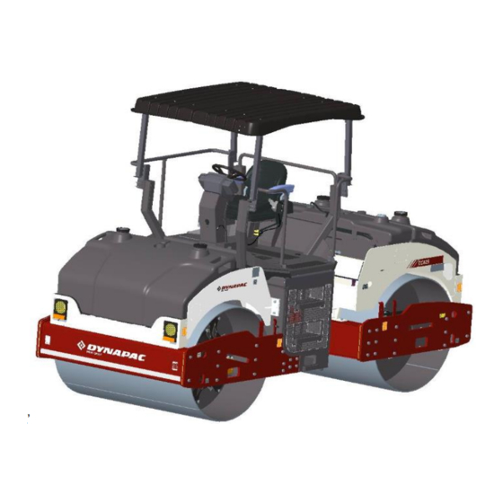
- Page 1 INSTRUCTION MANUAL Operating and Maintenance Vibratory rollers CC425 Engine: KOEL-4R1190NA1 – CEV Stage IV Serial number: *10300616CME010845- K’ 4812332527_A June-2021...
- Page 2 Manual Revisions Table 1: Revision History REV. DATE REVISION June 2021 New release Customer Acknowledgment • Dynapac reserves the right to make any changes or modifications without prior notice and without incurring any liability to retrofit machines previously shipped from the factory.
-
Page 3: Table Of Contents
Table of Contents Section 1: Introduction 1.1 General Information ................... Instruction Manual Location ..................Receiving the Roller ....................Identification Data ....................Roller Identification ....................Engine Identification ....................1.2 Roller Description ....................Identification of Major Components ................ Diesel Engine ......................Electrical System ....................Main and Light Fuses ...................... - Page 4 Table of Contents Section 3: Special Instructions 3.1 Operational Limitations ..................Standard Lubricants and Other Recommended Oils and Fluids ......Higher Ambient Temperatures ................Lower Ambient Temperature - Freeze Risk ............Temperatures ....................... High Pressure Cleaning ..................Ambient Temperature Range ................Operating Conditions For Stability ................
- Page 5 Table of Contents Rotating Beacon Switch (Optional) ............... Direction Indicator Switch ..................Parking Brake On/Off Switch ................Electrical Control Panel ..................Functional description - Display ..................31 Transport mode ......................31 Direction of work ......................31 Hour meter ........................31 Fuel level ........................
- Page 6 Table of Contents Towing ........................... 46 6.6 Transporting the Roller ..................Transportation Procedures ................... Safety Precautions ......................49 Operator Checklist ......................49 Start Up ......................... 49 Before Driving ....................... 49 Roller preparation for Transport ................... 50 6.7 Special Conditions ................... Cold Weather Conditions ..................
- Page 7 Table of Contents Fuel Tank ......................Coolant system ........................67 Water Tank .......................... 67 Fixed scrapper ........................67 Brakes ........................Sprinkler System ....................7.6 Lubrication and Filters ..................Hydraulic Reservoir ....................Check Hydraulic Oil Level ..................... 69 Steering Cylinder and Steering Joint ..............Drum - Oil Level ....................
- Page 8 This page is intentionally blank...
-
Page 9: Section 1: Introduction
1.1 General Information This manual contains basic safety information, basic operation instructions, and preventive maintenance information of the Dynapac CC425 roller. The purpose of this manual is to provide the knowledge of the fundamental rules and criteria to be followed for on-site use and maintenance of the CC425 roller for the operator and site maintenance personnel. -
Page 10: Instruction Manual Location
Instruction Manual Location Identification Data The instruction manuals are located behind the An exact description of the model type and the operator seat within easy access. serial number of the roller facilitates fast and efficient response from our parts and service support operations. -
Page 11: Roller Identification
Roller Identification The roller product identification number (PIN) plate is located on left hand side of the engine frame. The PIN number is a 17 digit number which provides information about manufacturer, family model, check letter, no coding, production unit, and serial number. Figure 1-2: Location PIN Manufacturer Family/Model... -
Page 12: Engine Identification
Engine Identification Figure 1-4: Identification Plate Engine identification plate The engine identification plate is affixed to the right side of the engine. The engine identification plate provides model identification and other important data about the engine. Refer to the engine operation and maintenance manual for further information on the identification information. -
Page 13: 1.2 Roller Description
1.2 Roller Description The roller is a two self-propelled vibratory tandem rollers in the nine-metric tonnes class featuring 1690-mm wide drums. The roller is equipped with drive, brakes, and vibration on both drums. To permit optimum performance on a wide range of applications and site requirements, the roller is equipped with: •... -
Page 14: Diesel Engine
Figure 1-6: Major Components Left Side Rear light Rear light Cylinder Water tank Scraper Drum Seat Vibration motor Propulsion motor Sprinkler pump Platform Steering hitch Fuel tank Diesel Engine The roller is equipped with the water-cooled, straight four-cylinder BS IV diesel engine. Introduction... -
Page 15: Electrical System
Electrical System Figure 1-8: Fuses-View A The roller is equipped with 12V DC electrical system and 90A alternator. Figure 1-7: Electric System 10A -Fuse D and E 40A - Main and Light fuse 30A - Mini Relay Battery Disconnector Switch 100A - Starter Relay 30A- Engine ECU fuse Battery disconnector... - Page 16 Figure 1-9: Fuses- View B Figure 1-10: Fuse Boxes in Switch Box Fuse box Fuse for Driving Lights Fuse The flat pin, type C (medium) fuses and 20A fuse are used for driving lights. Table 1-2: Fuse Function and Amperage Function Amperage Main fuse...
-
Page 17: Propulsion System/Transmission
Roller Applications Propulsion system/ Transmission The roller is built in accordance with international standards and recognized safety rules. The propulsion system is a hydrostatic system Nevertheless, misuse may constitute a risk to the life with a hydraulic pump supplying two motors with and limb of the user or third parties, and may cause gear box connected in parallel. - Page 18 This page is intentionaly left blank...
-
Page 19: Section 2:Safety First
Section 2:Safety First 2.1 General Information This information is intended as a guide for trained and qualified personnel who are aware of the dangers involved in handling potentially hazardous equipment. It is not intended to contain a complete list of all safety precautions which should be observed by personnel using this equipment. -
Page 20: Warnings And Cautions
Warnings and Cautions Personnel Protective Equipment Throughout the manual, Warnings, Cautions, and Notes symbols are used to designate instructions Anyone working around the roller must wear of particular importance. Look for these symbols approved safety equipment (safety shoes or which point out items of extreme importance to protective footwear, safety glasses, hearing you and your co-workers’... -
Page 21: Operating Safety
Operating Safety Driving Near Edges Know the working area. Familiarize with work site While driving near an edge make sure to maintain obstructions and any other potential hazards in 2/3 of the drum width on the solid ground. the area. N o t e The roller's center of gravity moves outwards when steering. -
Page 22: Slopes
Slopes Hydraulic Maintenance Safety The slope angle is measured on a hard, flat surface with the roller stationary. The steering The normal operating temperature of hydraulic oil angle was zero, the vibration was switched OFF is hot enough to cause serious burns. Use and all tanks were full. -
Page 23: Transporting
Transporting • Use only appropriate means of transport and lifting gear of adequate capacity. • Fastening of loads and instructing the crane operators should be entrusted to the experienced persons only. The person giving the instructions must be within sight or sound of the operator. -
Page 24: 2.2 Equipment Safety Decals
2.2 Equipment Safety Decals Before you operate, maintain, work around, or in any other way use this roller, read and understand the safety decals and safety labels located on the roller. Follow all directions on the labels. Do not remove or deface the labels. -
Page 25: Section 3:Special Instructions
Section 3:Special Instructions 3.1 Operational Limitations Standard Lubricants and Other Recommended Oils and Fluids Before leaving the factory, the systems and components are filled with the oils and fluids specified in the lubricant specification. These are suitable for: • Ambient temperatures in the range of 4°C to +50°C (39.2°F to 122°F) •... -
Page 26: High Pressure Cleaning
N o t e High Pressure Cleaning Specifications represented are calculated values at 100% efficiency. Do not spray water directly onto electrical Operator life may be endangered if the components or the instrument panels. following is not complied with. Do not add attachments to the roller that intrude into Place a plastic bag over the fuel filler cap and the operator protective area, reduce... -
Page 27: Jump Starting
Jump Starting Do not connect the negative cable to the negative terminal on the dead battery. A spark can ignite the oxy-hydrogen gas formed around the battery. Check the battery used for jump starting has the same voltage as the dead battery. 1. - Page 28 This page is intentionaly left blank...
-
Page 29: Section 4: Specifications
Section 4: Specifications 4.1 Weight and Dimensions Figure 4-1:Dimensions, Side View Table 4-1:Weight and Dimensions Side View Wheel base 2785 mm (109.6 in) Length 4340 mm (170.9 in) Height, with canopy 3140 mm (123.6 in) Height, without canopy 2460 mm (96.9 in) Thickness 17 mm (0.7 in) Operating mass... -
Page 30: Diesel Engine
Figure 4-2:Dimensions Top View Table 4-2:Weight and Dimensions Top View Turning radius outer 6500 mm (255.9 in) Turning radius inner 4800 mm (188.9 in) Drum width 1690 mm (66.5 in) Steering angle +/- 28 degree Diesel Engine Table 4-3: Diesel Engine Engine Model HP (kW) rpm... -
Page 31: Fluid Volume
Fluid Volume Table 4-4:Fluid Volumes Fuel tank 180 L (47.5 gal) Water tank Front side 400 L (105.6 gal) Rear side 400 L (105.6 gal) Hydraulic tank 62 L (16.3 gal) Hydraulic system 13 L (3.4 gal) Drum oil 14 L (3.7 gal) each Coolant - Premixed coolant 18.5 L (4.89 gal) Working Capacity... - Page 32 This page is intentionaly left blank...
-
Page 33: Section 5: Operation Controls
Section 5: Operation Controls 5.1 Instruments and Controls This section provides basic information about the operating controls, instruments, and indicators located on the consoles and around the roller. The operator console is located in front of the operator seat under the steering wheel. The slim profile and quick opening side panels provide easy access for maintenance and service. -
Page 34: Functional Description - Keypad
Functional Description – Keypad Working mode Amplitude, hight/low Working lights Rotating beacon (Not Applicable) Sprinkler Timer Sprinkler Manual/Auto Engine speed selector Horn Symbol Designation Function LED color LED OFF → Transport mode Work mode LED LEFT → Working mode, vibration LED LEFT →... -
Page 35: Starter Switch
Starter Switch Speed selector The Starter switch starts and stops the engine. The Speed selector regulates the speed of the There are three positions in the starter switch: engine. In the ON LED Left position, the engine idles and in the ON LED Right position the •... -
Page 36: Emergency Stop
Sprinkler Switch Emergency Stop Figure 5-7: Sprinkler Manual/Auto The Emergency stop button is used to stop the A. Sprinkler Manual/Auto engine in an emergency situation which cannot be B. Sprinkler timer shut off in an usual manner. It switches off the engine and activates the brakes. -
Page 37: Horn Button
Horn Button Drum Selector Switch Depending on the Drum selector, the vibration is The Horn button is located on the activated in the following places. keypad button no 7 Press the button to activate the horn. Left side button Activates vibration for front drum. -
Page 38: Working Light Switch
Working Light Depress the switch to turn on the rotating beacon. Switch Figure 5-15: Rotating Beacon Switch Depress the Working light switch to turn on the working lights. Figure 5-13: Working Lights Direction Indicator Switch The direction indicators are blinking lamps mounted near the left and right, front and rear corners of the roller. -
Page 39: Functional Description - Display
Electrical control system Functional Description – Display When the ignition key is activated to position 1, the start screen appears on the display (Fig. 1). This is shown for a two seconds and then switches over to the status screen. Transport mode Fig. -
Page 40: Vibration Status
Vibration status Vibration status activated on the drum (8). Automatic Vibration Control – AVC If AVC is activated from display selector switch, machine will runs with automatic vibration meaning that every time you don’t need to press vibration switch on FNR lever. Refer beside snap for this & follow below conditions. 1) Select button of display in front of AVC=it will appear on display as shown in beside-encircled snap. -
Page 41: Control Panel Warnings Symbols
Control Panel Warnings Symbols Warning lights turn on when the starter switch is turned to the on position and turn off when the engine is started. If the lights turn on even when the engine is running indicates a faulty condition. Table 5-1:Warning Lights Designation Function... -
Page 42: Control Panel Notification Symbols
Control Panel Notification Symbols Notifications are displayed when the starter switch is turned to the on position and notifies that corresponding systems are operating. Table 5-2:Notification Lights Designation Function Description The lamp illuminates when the parking brake is Parking brake indicator activated. - Page 43 Control Panel Notification Symbols Table 5-2:Notification Lights Designation Function Description If by mistake P-Brake Sw.is ON (disabled) & if Cranking Attempt when P- anyone trying to crank the engine-then beside Brake disabled warning symbol should appear on display. Whenever FNR lever either in forward or Cranking Attempt when FNR reverse direction &...
- Page 44 Control Panel Notification Symbols Table 5-2:Notification Lights Designation Function Description Symbolic representation of machine position (in Neutral Check & ensure Neutral symbol as 'N' & 'N', Non neutral: Check & whenever FNR lever comes in correct neutral ensure Neutral symbol as 'N' position.
-
Page 45: Section 6: Inspections And Operations
Section 6: Inspections and Operations 6.1 General Information N o t e If you are not experienced with the roller controls, read and understand Section 5 - Operation Controls. The following operational hints should be observed: • Do not speed the engine when it is cold. •... -
Page 46: Check Engine Oil Level
Check Engine Oil Level Check Engine Coolant Level • Hot oil and hot components can cause Check the coolant level through transparent personal injury. Do not allow hot oil or plastic of expansion tank. Fill the cooling system hot components to contact the skin. when coolant is empty. -
Page 47: Check Fuel Level
Check Fuel Level Check Batteries Fuel is flammable and may cause serious Batteries contain an acid and can cause injury or death. Shut off the engine, injury. Battery fumes can ignite and extinguish all open flames, and do not explode. Do not smoke when observing smoke while filling the tank. -
Page 48: Before Starting The Engine
6.2 Before Starting the If any controls, instruments, or devices do Engine not function correctly report the defects to the proper personnel. Defects must be corrected before starting and operating Remember to carry out daily maintenance before the roller. starting the engine. Refer to Section 7 - Maintenance. -
Page 49: Check The Instruments And Lamps
Check the Instruments and Lamps N o t e Make sure that the Emergency stop is pulled out and the parking brake is activated. If the forward/reverse lever is in neutral, the automatic brake function is engaged. 1. Turn on the switch. 2. -
Page 50: 6.3 Operating The Roller
6.3 Operating the Roller 6. Make sure the Engine RPM switch is turned to low position. Operation Figure 6-5: Engine RPM 1. Before the roller start up, a pre-operational general inspection of the roller must be performed in accordance with those instructions previously mentioned and in the instructions found in Section 7 - Maintenance. -
Page 51: Vibration On Selected Drum
N o t e As a general rule, do not operate the Vibration on Selected Drum starter motor more than 30 seconds at a time without pausing to allow the 1. Activate the Working mode and High/low starter motor to cool for at least two amplitude from keypad button 1 and 2. -
Page 52: Switching Off
Switching Off 1. Press the Vibration control button to the off position. 2. Set the FNR lever to the neutral position. 3. Turn the Engine RPM switch to low and allow the engine to idle for a few minutes to cool. 4. -
Page 53: 6.4 Lifting And Handling
6.4 Lifting and Handling Lifting the Roller • Use a crane/forklift to lift the equipment. Locking the Articulation • Pay attention when lifting and balancing the N o t e Lock the steering joint, before lifting equipment. the roller. • Seek a person to guide the way when lifting 1. -
Page 54: 6.5 Towing The Roller
6.5 Towing the Roller Towing The roller can be moved up to 300 meters Towing Information (1,000 ft) using the instructions below. Proper equipment must be used to prevent N o t e Chock the drum to prevent the roller damage to the vehicle and the roller during any from moving when the brakes are tow. - Page 55 4. Tighten the knob 3 clockwise Engaging the Brakes 1. Turn knob 3 counter clockwise after towing. Figure 6-11:Tighten Step 2. Tighten the Allen screw 2 to original position and then tighten nut 3. Figure 6-13:Towing Knob 3 5. Operate the lever for 10 to 12 times to manually release the brake.
-
Page 56: Transporting The Roller
6.6 Transporting the Start Up Roller 1. Before starting the engine, check inside, outside, and underneath the roller for people or obstructions. Transportation Procedures 2. Always horn before starting the roller to alert Safety Precautions everyone in the area. Before moving the roller on public roads, check for 3. - Page 57 Roller preparation for Transport Figure 6-14: Securing for Loading Lashing wire Chocks 1. Chock the drums securely. 2. Support the drum frame firmly to prevent overloading of the rubber suspension of the drum. 3. Anchor the roller securely with lashing wire at all the four corners. Inspections and Operations...
-
Page 58: Roller Preparation For Transport
Figure 6-15: Securing the Vibratory Roller For Transport Table 6-1:Lashings' Permitted Distance The lashings' permitted distance interval in meters (1 - 4: Double lashings, LC at least 1.7 tonnes (1700 daN), STF 300 kg (300daN)) Double L Double L 0,6 - 3,0 0,1 - 3,0 The distance L above is between points D and E. -
Page 59: 6.7 Special Conditions
6.7 Special Conditions Cold Weather Conditions • Refer to Section 7 - 7.3 Refill Capacities/Lubricants in the maintenance section for information regarding cold weather lubricants, hydraulic fluids, coolants, fuel, and the like. • Use winter grade diesel fuel for operation at subzero temperatures. •... -
Page 60: Long-Term Parking
• Lubricate the steering joint bearings and both bearings on the steering cylinder with grease. Grease the steering cylinder piston with conservation grease. Grease the hinges on the doors to the engine compartment and the cab. Grease both ends of the forward/reverse control (bright parts). -
Page 61: Section 7:Maintenance
Section 7:Maintenance 7.1 General Information Safety should be the main concern for anyone working on or around the roller. Do not perform any function that could put someone in danger. Always wear proper safety gear while working on or around the roller. This includes an approved hard hat, safety glasses, steel toe shoes, gloves, respirator, and ear protection. -
Page 62: 7.2 Maintenance Schedule
7.2 Maintenance Schedule Maintenance Schedule Information The maintenance schedule shows those items requiring regular service and the interval at which they are performed. A regular service program is geared to the items listed under each interval. These intervals are based on average operating conditions. Before each consecutive interval is performed, all of the maintenance requirements from the previous interval must also be performed. - Page 63 Table 7-4: Maintenance at 250 Hours/750 Hours/Three Months Description Action Lubrication See engine manual Engine V Belt Condition Check Table 7-5: Maintenance at 500 Hours/Six Months Description Action Lubrication Engine oil filter element Change See engine manual Engine oil Change See engine manual Pre fuel filter element Change...
- Page 64 Table 7-7: Maintenance at 2,000 Hours/Two Years Description Action Lubrication Engine oil filter element Change See engine manual Engine oil Change See engine manual Pre fuel filter element Change See engine manual Main fuel filter Change See engine manual Engine primary air filter Change Safety filter Change...
-
Page 65: 7.3 Refill Capacities/Lubricants
7.3 Refill Capacities/Lubricants General Information Lubrication is an essential part of preventive maintenance, affecting to a great extent the useful life of the unit. Periodic lubrication of the moving parts reduces to a minimum the possibility of the mechanical failures. The lubrication chart that follows in this section shows those items requiring regular service and the interval at which they should be performed. -
Page 66: Lubrication Chart
Lubrication Chart Periodic lubrication requirements are listed in the following Lubrication Chart. These requirements include lubricant checks and greasing designated areas of the roller. Description Part Number Remarks Quantity Engine oil 4812161866 Dynapac engine oil 50 5 L (1.3 gallons) Hydraulic oil D971800001 Dynapac hydraulic 300... - Page 67 Table 7-8: Maintenance Symbols Symbol Description Symbol Description Engine oil level Air filter Engine oil filter Battery Hydraulic reservoir level Sprinkler Hydraulic fluid filter Sprinkler water Recycling Drum oil level Lubrication oil Fuel filter Maintenance...
-
Page 68: 7.4 Standard Torque Values
7.4 Standard Torque Values Use only the proper tools (inches) on hardware. Other tools may not fit properly and may slip and cause injury. Head Markings Fasteners should be replaced with the same grade or a higher grade. If higher grade fasteners are used, these should only be tightened to the strength of the original grade fastener. - Page 69 Metric coarse screw thread, bright galvanized (fzb): M-thread Size 12.9, 8.8 Oiled 8.8 Dry 10.9 Oiled 10.9, Dry 12.9, Dry Oiled 1080 1130 1260 1580 1770 1900 2100 Metric coarse thread, zinc-treated (Dacromet/GEOMET) M-thread Size 10.9 Oiled 10.9 Dry 12.9 Oiled 12.9 Dry 1010 1215...
-
Page 70: Maintenance As Required
7.5 Maintenance as Loose Bolted Connections Required If any loose nuts or bolts are found during the frequent walk-around and the daily inspections, Service as Required make sure they are properly torqued. Refer to 7.4 Standard Torque Values for the required torque The preventive maintenance and service in this for all bolt sizes and grades. -
Page 71: Air Cleaner Pre-Cleaner
Air Cleaner Pre- Cleaner Figure 7-2: Air Cleaner Elements Wipe clean the inside of the cover and the filter housing. Wipe also both surfaces for the outlet pipe. N o t e Check that the hose clamps between the filter housing and the suction hose are tight and that the hoses are intact. -
Page 72: Cleaning The Filter Element
N o t e 8. Carefully install the cleaned or new main Replace air filter element after two filter. cleaning interval Air Circulation Figure 7-3: Air Filter Check that the engine has free circulation of cooling air through the grille in the engine compartment. -
Page 73: Engine
Engine Batteries Refer to the engine service and maintenance The following battery maintenance must be manuals for specific information on the engine carried out as part of the 250 hour routine maintenance. maintenance schedule. N o t e Switch off the engine before filling the Batteries contain an acid and can cause oil. -
Page 74: Check Electrolyte Level
Check Electrolyte Level Fuel Tank 1. Shut off the engine. Refuel the tank every day before starting the roller. 2. Lockout/tagout the roller as per the site specific procedure. 1. Unscrew the lockable tank cap. 3. Check the electrolyte level and keep the electrolyte level above the plates. -
Page 75: Coolant System
Coolant System Water Tank Unscrew the tank cap and fill with clean water. Do Check that all hoses/hose connectors are intact not remove the strainer. See technical and tight. Fill with coolant as specified in the specifications for the tank volume. lubricants specification. -
Page 76: Brakes
4. Tighten all the screws after adjustment. Sprinkler System Start the sprinkler system and make sure that Figure 7-11: Drum nozzles are clogged. If necessary, clean clogged nozzles and the coarse filter located by the water pump. The sprinkler system should be drained if there is a risk of freezing. -
Page 77: Lubrication And Filters
7.6 Lubrication and Check Hydraulic Oil Level Filters If the hydraulic oil level is low, add hydraulic oil. Hydraulic Reservoir 1. Level the roller. 2. Check the reservoir oil level by viewing the The hydraulic reservoir oil level must be checked sight gauge. -
Page 78: Steering Cylinder And Steering Joint
Steering Cylinder and Drum - Oil Level Steering Joint 1. Run the roller slowly until the oil plug is opposite to one of the inspection holes. The steering cylinder is located under the operator platform. There is a grease fitting near the base 2. -
Page 79: Check Drum Gear Oil Level
Check Drum Gear Oil Level Housekeeping 1. Move the roller until the inspection/filling The complete roller must be given a weekly holes are in position for filling. cleaning. Daily cleaning will be required if material is adhering to the roller working parts. 2. - Page 80 This page is intentionaly left blank...
- Page 81 www.dynapac.com Dynapac Road Construction Equipment (India) Pvt. Ltd Plot no 01, Gat no. 163-168, Alandi Markal road, Village: Fulgaon, Taluka: Haveli, Dist: Pune- 412216, India...
Need help?
Do you have a question about the DYNAPAC CC425 and is the answer not in the manual?
Questions and answers