Table of Contents
Advertisement
Instruction manual
Instruction manual
Operating & Maintenance
Operating & Maintenance
4812163901_A.pdf
4812163901_A.pdf
Vibratory roller
Vibratory roller
Honda GX630RH QYD
Honda GX630RH QYD
Serial number
Serial number
10000303xxA023833 -
10000303xxA023833 -
Translation of original instruction
Translation of original instruction
Reservation for changes
Reservation for changes
Printed in Sweden
Printed in Sweden
CC900G
CC900G
Engine
Engine
Advertisement
Table of Contents

Related Manuals for Fayat Group Dynapac CC900G


Summary of Contents for Fayat Group Dynapac CC900G
- Page 1 Instruction manual Instruction manual Operating & Maintenance Operating & Maintenance 4812163901_A.pdf 4812163901_A.pdf Vibratory roller Vibratory roller CC900G CC900G Engine Engine Honda GX630RH QYD Honda GX630RH QYD Serial number Serial number 10000303xxA023833 - 10000303xxA023833 - Translation of original instruction Translation of original instruction Reservation for changes Reservation for changes Printed in Sweden...
-
Page 3: Table Of Contents
Table of Contents Introduction ..........................1 The machine ....................1 Intended use ....................1 Warning symbols..................1 Safety information ..................1 General ....................... 2 Safety - General instructions....................5 Safety - when operating ......................7 Work driving ....................7 Driving near edges ..................8 Seated position ................... - Page 4 Hydraulic system..................17 Tightening torque ..................18 ROPS - bolts ..................... 19 Machine description ....................... 21 Gasoline engine ..................21 Electrical system ..................21 Propulsion system/Transmission .............. 21 Brake system .................... 21 Steering system ..................21 ROPS ......................21 Identification ......................22 Product and component plates ..............
- Page 5 Emergency stop ..................34 Operator position..................34 Starting ........................35 Starting the engine ..................35 Driving ........................36 Operating the roller ................... 36 Interlock/Emergency stop/Parking brake - Check ........37 Vibration ........................37 Manual vibration - Switching on ..............37 Braking ........................
- Page 6 Maintenance - Maintenance schedule ................... 55 Service and maintenance points ............... 55 General ..................... 56 Every 10 hours of operation (Daily)............56 After the first 20 hours of operation............57 After the FIRST 50 hours of operation ............57 Every 50 hours of operation ..............57 Every 100 hours of operation ..............
- Page 7 Maintenance - 200 / 400 / 600 / 800 h ................... 71 Spark plug - Replace................. 71 Engine's fuel filter - Check................. 72 Hydraulic fluid cooler - Cleaning (Option) ..........72 Engine oil and oil filter - Change ............... 73 Forward/Reverse controls and joints - Check and lubrication....
- Page 8 Air cleaner - replace insert ................ 90 Hydraulic fluid filter - Change ..............91 Engine oil and oil filter - Change ............... 91 Engine's fuel filter - Check................. 92 Hydraulic reservoir - fluid change.............. 93 Front drum - Changing the oil ..............94 Water tank - Cleaning ................
-
Page 9: Introduction
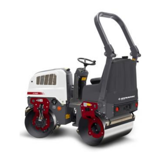
Introduction Introduction The machine Dynapac CC900G is a vibratory tandem roller in the 1,3 metric tonnes class featuring 900 mm wide drums. The machine is equipped with drive and brakes on both drums, and vibration on front drum. Intended use... -
Page 10: General
Introduction Replace immediately the instruction manuals if Replace immediately the instruction manuals if lost, damaged or unreadable. lost, damaged or unreadable. Ensure good ventilation (extraction of air by fan) Ensure good ventilation (extraction of air by fan) where the engine is run indoors. where the engine is run indoors. - Page 11 Introduction THINK ENVIRONMENT ! Do not release oil, THINK ENVIRONMENT ! Do not release oil, fuel and other environmentally hazardous fuel and other environmentally hazardous substances into the environment. Always send substances into the environment. Always send used filters, drain oil and fuel remnants to used filters, drain oil and fuel remnants to environmentally correct disposal.
- Page 12 Introduction 4812163901_A.pdf 2019-09-23...
-
Page 13: Safety - General Instructions
Safety - General instructions Safety - General instructions (Also read the safety manual) • • The operator must be familiar with the contents of the OPERATION section The operator must be familiar with the contents of the OPERATION section before starting the roller. before starting the roller. - Page 14 Safety - General instructions • • Do not make any changes or modifications to the roller that could affect Do not make any changes or modifications to the roller that could affect safety. Changes are only to be made after written approval has been given safety.
-
Page 15: Safety - When Operating
Safety - when operating Safety - when operating Prevent persons from entering or remaining in Prevent persons from entering or remaining in the danger area, i.e. a distance of at least 7 m the danger area, i.e. a distance of at least 7 m (23 ft) in all directions from operating machines. -
Page 16: Driving Near Edges
Safety - when operating Driving near edges Never operate with roller outside the edge, if the Never operate with roller outside the edge, if the substrate does not have full bearing strength or is substrate does not have full bearing strength or is close to a slope. -
Page 17: Special Instructions
Special instructions Special instructions Standard lubricants and other recommended oils and fluids Before leaving the factory, the systems and components are filled with the oils and fluids specified in the lubricant specification. These are suitable for ambient temperatures in the range -15°C to +40°C (5°F - 105°F). -
Page 18: Fire Fighting
Special instructions Fire fighting If the machine catches fire, use an ABC-class powder fire extinguisher. A BE-class carbon dioxide fire extinguisher can also be used. Roll Over Protective Structure (ROPS) Never carry out any welding or drilling in the Never carry out any welding or drilling in the Roll Over Protective Structure (ROPS). -
Page 19: Jump Starting
Special instructions Jump starting Do not connect the negative cable to the Do not connect the negative cable to the negative terminal on the dead battery. A spark negative terminal on the dead battery. A spark can ignite the oxy-hydrogen gas formed can ignite the oxy-hydrogen gas formed around the battery. - Page 20 Special instructions 4812163901_A.pdf 2019-09-23...
-
Page 21: Technical Specifications
Technical specifications Technical specifications Vibrations - Operator station (ISO 2631) The vibration levels are measured in accordance with the operational cycle described in The vibration levels are measured in accordance with the operational cycle described in EU directive 2000/14/EC on machines equipped for the EU market, with vibration switched EU directive 2000/14/EC on machines equipped for the EU market, with vibration switched on, on soft polymer material and with the operator’s seat in the transport position. -
Page 22: Dimensions, Side View
Technical specifications Dimensions, side view Dimensions Dimensions Wheelbase Wheelbase 1350 1350 53,1 53,1 Drum diameter Drum diameter 23,0 23,0 Height, with ROPS Height, with ROPS 2300 2300 90,5 90,5 Height, w/o ROPS Height, w/o ROPS 1585 1585 62,4 62,4 Ground clearance Ground clearance 10,3 10,3... -
Page 23: Dimensions, Top View
Technical specifications Dimensions, top view Dimensions Dimensions Width Width 38,2 38,2 Overhang Overhang 1,38 1,38 Turning radius, outside Turning radius, outside 2700 2700 106,3 106,3 Turning radius, inside Turning radius, inside 2660 2660 104,7 104,7 Drum shell thickness Drum shell thickness 35,4 35,4 α... -
Page 24: Weights And Volumes
Technical specifications Weights and volumes Weights Weights Operating mass (ISO6016) Operating mass (ISO6016) 1250 kg 1250 kg 2767 lbs 2767 lbs Fluid volumes Fluid volumes Fuel tank Fuel tank 23 liters 23 liters 6,0 gal 6,0 gal Water tank Water tank 190 liters 190 liters 50 gal... -
Page 25: Hydraulic System
Technical specifications Hydraulic system Opening pressure Opening pressure Drive system Drive system 27,0 27,0 3915 3915 Supply system Supply system Vibration system Vibration system 22,0 22,0 3190 3190 Control systems Control systems 1015 1015 Brake disengagement Brake disengagement 2019-09-23 4812163901_A.pdf... -
Page 26: Tightening Torque
Technical specifications Tightening torque Tightening torque in Nm for oiled or dry bolts tightened with a torque wrench. Metric coarse screw thread, bright galvanized (fzb): STRENGTH CLASS: 8.8, Oiled 8.8, Oiled 8.8, Dry 8.8, Dry 10.9, Oiled 10.9, Oiled 10.9, Dry 10.9, Dry 12.9, Oiled 12.9, Oiled... -
Page 27: Rops - Bolts
Technical specifications ROPS - bolts Bolt dimensions : Bolt dimensions : M12 (PN 4700508063) M12 (PN 4700508063) Strength class : Strength class : Tightening torque : Tightening torque : 70 Nm 70 Nm ROPS-bolts which are to be torque tightened ROPS-bolts which are to be torque tightened must be dry. - Page 28 Technical specifications 4812163901_A.pdf 2019-09-23...
-
Page 29: Machine Description
Machine description Machine description Gasoline engine The machine is equipped with a air-cooled, four-stroke, gasoline engine with V-twin design and horisontal axle. Electrical system The machine has the following control units (ECU, Electronic Control Unit) and electronic units. • Main ECU (for the machine) Propulsion system/Transmission The propulsion system is a hydrostatic system with a hydraulic pump supplying two motors connected in... -
Page 30: Identification
Machine description ROPS structure without first having discussed the modification with Dynapac's production unit. Dynapac determines whether the modification could result in the approval according to the ROPS standards becoming invalid. Identification Product and component plates Product plate - Product Identification Number (PIN), model/type designation Product plate - Product Identification Number (PIN), model/type designation Engine plate - Type description, product and serial numbers Engine plate - Type description, product and serial numbers... -
Page 31: Product Identification Number On The Frame
Machine description Please state the machine’s PIN when ordering spares. Product identification number on the frame The machine PIN (Product Identification Number) (1) is punched on the right edge of the front frame. Fig. PIN Front frame 2019-09-23 4812163901_A.pdf... -
Page 32: Engine Plates
Machine description Engine plates The engine serial number (1) is punched below the starter. Please specify the engine serial number when ordering spares. Refer also to the engine manual. The engine's EPA plate (2). Figure. Engine 1. Serial number 2. EPA plate (USA) 4812163901_A.pdf 2019-09-23... -
Page 33: Decals
Machine description Decals Location - decals 1, 9 Fig. Location, decals and signs Warning, Crush zone Warning, Crush zone 4700903422 4700903422 Lifting point Lifting point 4700357587 4700357587 Warning, Rotating engine components 4700903423 Warning, Rotating engine components 4700903423 Hydraulic fluid level Hydraulic fluid level 4700272373 4700272373... -
Page 34: Location - Decals, California
Machine description Location - decals, CALIFORNIA Proposition 65 Warning, CALIFORNIA Warning, CALIFORNIA 4812130471 4812130471 Proposition 65 Proposition 65 Fig. Location Safety decals Always make sure that all safety decals are completely legible, and remove dirt or order new decals if they have become illegible. - Page 35 Machine description 4700903459 Warning - Instruction manual The operator must read the safety, operation and maintenance instructions before operating the machine. 4700908229 Warning - Risk of crushing The articulation must be locked when lifting. Read the instruction manual. 2019-09-23 4812163901_A.pdf...
- Page 36 Machine description 4812130471 Warning CALIFORNIA - Proposition 65 4812163901_A.pdf 2019-09-23...
-
Page 37: Info Decals
Machine description Info decals Handbook compartment Handbook compartment Gasoline Gasoline Lifting point Lifting point Hydraulic oil level Hydraulic oil level Hoisting plate Hoisting plate Securing point Securing point Instruments/Controls Locations - Instruments and controls 1. Ignition key 1. Ignition key 7. -
Page 38: Function Description
Machine description Function description Designation Designation Symbol Symbol Function Function Starter switch Starter switch The electric circuit is broken. The electric circuit is broken. All instruments and electrical controls are supplied All instruments and electrical controls are supplied with power with power Starter motor activation. -
Page 39: Electrical System
Machine description Electrical system Relays and fuses on the machine The figure shows the positions of the various fuses and relays. The table below gives their amperage and function. All fuses are flat pin fuses. Relays Relays Starting Starting 12V 30A 12V 30A Start, vibration, brake Start, vibration, brake... - Page 40 Machine description 4812163901_A.pdf 2019-09-23...
-
Page 41: Operation
Operation Operation Before starting Operator’s seat - Adjusting Adjust the operator’s seat so that the position is comfortable and so that the controls are within easy reach. The seat can be adjusted lengthways (1). Fig. Operator's seat 1. Length adjustment Sprinkler - Check Make sure that the parking brake (3) is activated. -
Page 42: Parking Brake
Operation Parking brake Activate the parking brake (3) before leaving the Activate the parking brake (3) before leaving the machine. machine. The machine can be started with the parking brake deactivated. Emergency stop The machine can only be started if the emergency stop (10) is deactivated. -
Page 43: Starting
Operation Starting Starting the engine Make sure that the parking brake (3) is activated. Sit down in the operator's seat and set the forward/reverse lever (6) in neutral. You cannot start the gasoline engine with the lever in any other position. Set the RPM control (2) to idle. -
Page 44: Driving
Operation Driving Operating the roller Under no circumstances is the machine to be Under no circumstances is the machine to be operated from the ground. The operator must be operated from the ground. The operator must be seated at the machine during all operation. seated at the machine during all operation. -
Page 45: Interlock/Emergency Stop/Parking Brake - Check
Operation Interlock/Emergency stop/Parking brake - Check The interlock, emergency stop and parking brake must The interlock, emergency stop and parking brake must be checked daily before operating. A function check of be checked daily before operating. A function check of the interlock and emergency stop requires a restart. -
Page 46: Service Brake
Operation Service brake When starting and driving a machine that is cold, When starting and driving a machine that is cold, remember that the hydraulic fluid is also cold and remember that the hydraulic fluid is also cold and that braking distances can be longer than normal that braking distances can be longer than normal until the machine reaches the working temperature. -
Page 47: Switching Off
Operation Switching off Turn the engine speed control (2) back to idling.Allow the engine to idle for few minutes to cool. Activate the parking brake (3). Turn the starter switch (1) to the left to shut off position. Fig. Instrument panel 1. - Page 48 Operation 4812163901_A.pdf 2019-09-23...
-
Page 49: Miscellaneous
Miscellaneous Miscellaneous Locking the articulation Turn the steering wheel to the straight ahead position. Raise the locking arm (1) and turn 180 degrees downward. Ensure that the cotter pin (2) is guided into its lower position correctly for locking the articulation. Fig. -
Page 50: Securing Cc900G For Loading
Miscellaneous Securing CC900G for loading Securing the CC900G vibratory roller from Dynapac for transport. Roller loaded in forward direction Direct of travel 1 - 2 1 - 2 = double lashings, i.e. one lashing with two parts secured to two different lashing mounts, = double lashings, i.e. -
Page 51: Retractable Rops (Optional)
Miscellaneous Load carrier Load carrier When loaded, the vibratory roller is centered laterally on the platform (± 5 cm). When loaded, the vibratory roller is centered laterally on the platform (± 5 cm). The parking brake is applied and in good working condition, and the articulated joint lock is The parking brake is applied and in good working condition, and the articulated joint lock is closed. -
Page 52: Towing
Miscellaneous To retract the ROPS, release the tensioning screw (1), and pull out the pin (2) and stud (3). Do the same on both sides. Lower the ROPS backwards if there is space. Remember to dismantle the rotating warning light Remember to dismantle the rotating warning light before lowering the ROPS. -
Page 53: Releasing The Brake
Miscellaneous Releasing the brake 1. Remove the 2 plugs (191). Figure. Releasing the brake 2. Press the screws (192) inwards to compress the springs (193) so that the screw reaches the brake (107) inner thread. 3. Tighten the two screws (192) alternately a little at a time so that the brake piston (107) loose (screw approximately 2 turns). -
Page 54: Towing The Roller
Miscellaneous Restored brake Restored brake Undo the two screws (192) alternately, and then insert Undo the two screws (192) alternately, and then insert the plugs (191). the plugs (191). Tightening torque Tightening torque Screws (192) Screws (192) Plugs (191) Plugs (191) Towing the roller A towing bar must be used when towing, as the A towing bar must be used when towing, as the... -
Page 55: Operating Instructions - Summary
Operating instructions - Summary Operating instructions - Summary Follow the SAFETY INSTRUCTIONS specified in the Safety Manual. Follow the SAFETY INSTRUCTIONS specified in the Safety Manual. Make sure that all instructions in the MAINTENANCE section are followed. Make sure that all instructions in the MAINTENANCE section are followed. Set the Emergency stop to its pulled-out position. - Page 56 Operating instructions - Summary 4812163901_A.pdf 2019-09-23...
-
Page 57: Preventive Maintenance
Preventive maintenance Preventive maintenance Complete maintenance is necessary for the machine to function satisfactorily and at the lowest possible cost. The Maintenance section includes the periodic maintenance that must be carried out on the machine. The recommended maintenance intervals assume that the machine is used in a normal environment and working conditions. - Page 58 Preventive maintenance CALIFORNIA Proposition 65 Decal and location of decal shown in section Machine description. 4812163901_A.pdf 2019-09-23...
-
Page 59: Maintenance - Lubricants And Symbols
Maintenance - Lubricants and symbols Maintenance - Lubricants and symbols Always use high-quality lubricants and the Always use high-quality lubricants and the amounts recommended. Too much grease or amounts recommended. Too much grease or oil can cause overheating, resulting in rapid oil can cause overheating, resulting in rapid wear. - Page 60 Maintenance - Lubricants and symbols ENGINE OIL ENGINE OIL Air temperature -15°C - +50°C Air temperature -15°C - +50°C Dynapac Engine 200 Dynapac Engine 200 P/N 4812161855 (5 liters) P/N 4812161855 (5 liters) (5°F-122°F) (5°F-122°F) P/N 4812161856 (20 liters) P/N 4812161856 (20 liters) HYDRAULIC FLUID HYDRAULIC FLUID Air temperature -15°C - +40°C...
-
Page 61: Maintenance Symbols
Maintenance - Lubricants and symbols Maintenance symbols Engine, oil level Engine, oil level Air filter Air filter Engine, oil filter Engine, oil filter Battery Battery Hydraulic reservoir, level Hydraulic reservoir, level Sprinkler Sprinkler Hydraulic fluid, filter Hydraulic fluid, filter Sprinkler water Sprinkler water Drum, oil level Drum, oil level... - Page 62 Maintenance - Lubricants and symbols 4812163901_A.pdf 2019-09-23...
-
Page 63: Maintenance - Maintenance Schedule
Maintenance - Maintenance schedule Maintenance - Maintenance schedule Service and maintenance points 12, 13 Fig. Service and maintenance points 1. Water tank, filling 1. Water tank, filling Air cleaner Air cleaner Hydraulic fluid, filling Hydraulic fluid, filling 2. Forward/Reverse lever 2. -
Page 64: General
Maintenance - Maintenance schedule General Periodic maintenance should be carried out after the number of hours specified. Use the daily, weekly etc. periods where number of hours cannot be used. Remove all dirt before filling, when checking Remove all dirt before filling, when checking oils and fuel and when lubricating using oil or oils and fuel and when lubricating using oil or grease. -
Page 65: After The First 20 Hours Of Operation
Maintenance - Maintenance schedule After the first 20 hours of operation Refer to the contents to find the page number of the sections referred to ! Pos. Pos. Action Action Comment Comment in fig in fig Change the engine oil Change the engine oil Refer to the engine manual Refer to the engine manual... -
Page 66: Every 200 / 400 / 600 / 800 Hours Of Operation
Maintenance - Maintenance schedule Every 200 / 400 / 600 / 800 hours of operation Refer to the contents to find the page number of the sections referred to ! Pos. Pos. Action Action Comment Comment in fig in fig Replace the spark plugs Replace the spark plugs Refer to the engine manual. -
Page 67: Every 1000 Hours Of Operation
Maintenance - Maintenance schedule Every 1000 hours of operation Refer to the contents to find the page number of the sections referred to ! Pos. Pos. Action Action Comment Comment in fig in fig Replace the spark plugs Replace the spark plugs Refer to the engine manual. -
Page 68: Every 2000 Hours Of Operation
Maintenance - Maintenance schedule Every 2000 hours of operation Refer to the contents to find the page number of the sections referred to ! Pos. Pos. Action Action Comment Comment in fig in fig Replace the spark plugs Replace the spark plugs Refer to the engine manual Refer to the engine manual Check idling revs... -
Page 69: Maintenance, 10H
Maintenance, 10h Maintenance, 10h Every 10 hours of operation (Daily) Park the roller on a level surface. Park the roller on a level surface. The engine must be switched off and the The engine must be switched off and the parking brake activated when checking or parking brake activated when checking or adjusting the roller, unless otherwise specified. -
Page 70: Refueling
Maintenance, 10h Refueling Refuel the tank every day before starting work. Open the tank cap and fill through the filler pipe (1). Never refuel while the engine is running. Do not Never refuel while the engine is running. Do not smoke and avoid spilling fuel. -
Page 71: Air Circulation - Check
Maintenance, 10h Air circulation - Check Ensure that the gasoline engine has free circulation of cooling air through the vents in the hood. Fig. Engine cover 1. Cooling air grille/engine Scrapers - Check, adjustment Make sure that the scrapers are undamaged. Adjust the scrapers if necessary in the following way: For firmer application of the scraper, undo the locking nut (2) and turn it to the right until the desired... -
Page 72: Warning Lamps - Check
Maintenance, 10h Warning lamps - Check Check that the warning lamp on the control panel is functional (12). Fig. Control panel 3. Parking brake 12. Parking brake warning lamp Air cleaner - check Check that hoses and couplings are not leaking and that the air cleaner cover is on properly. -
Page 73: Maintenance - 20H
Maintenance - 20h Maintenance - 20h Park the roller on a level surface. Park the roller on a level surface. The engine must be switched off and the The engine must be switched off and the parking brake activated when checking or parking brake activated when checking or adjusting the roller, unless otherwise specified. - Page 74 Maintenance - 20h Fit the drain plug (2) to the end of the hose. Fill with fresh engine oil (see under Lubricants heading for the correct oil grade), refit the filler cap (4) and check the level on the dipstick. Start the engine and check the tightness around the oil filter.
-
Page 75: Maintenance - 50H
Maintenance - 50h Maintenance - 50h Every 50 hours of operation (Weekly) Park the roller on a level surface. Park the roller on a level surface. The engine must be switched off and the The engine must be switched off and the parking brake activated when checking or parking brake activated when checking or adjusting the roller, unless otherwise specified. -
Page 76: Air Cleaner - Cleaning
Maintenance - 50h Air cleaner - cleaning Unclip the four lock catches (1) and lift the air cleaner's cover (2). Lift out the plastic foam and clean it in warm soapy water, rinse and dry. Clean the air filter by tapping it with the palm of the hand or blow compressed air (not exceeding 207 kPa (2,1 kgf/cm2, 30 psi)) through the filter element from the air cleaner case side. -
Page 77: Maintenance - 100H
Maintenance - 100h Maintenance - 100h Park the roller on a level surface. Park the roller on a level surface. The engine must be switched off and the The engine must be switched off and the parking brake activated when checking or parking brake activated when checking or adjusting the roller, unless otherwise specified. - Page 78 Maintenance - 100h 4812163901_A.pdf 2019-09-23...
-
Page 79: Maintenance - 200 / 400 / 600 / 800 H
Maintenance - 200 / 400 / 600 / 800 h Maintenance - 200 / 400 / 600 / 800 h Park the roller on a level surface. Park the roller on a level surface. The engine must be switched off and the The engine must be switched off and the parking brake activated when checking or parking brake activated when checking or... -
Page 80: Engine's Fuel Filter - Check
Maintenance - 200 / 400 / 600 / 800 h Engine's fuel filter - Check Switch off the engine and push in the Switch off the engine and push in the reserve/parking brake knob. reserve/parking brake knob. Use caution. Wear gloves. Use caution. -
Page 81: Engine Oil And Oil Filter - Change
Maintenance - 200 / 400 / 600 / 800 h Engine oil and oil filter - Change Run the engine until it is warm before draining the oil. Switch off the engine and push in the Switch off the engine and push in the reserve/parking brake knob. -
Page 82: Forward/Reverse Controls And Joints - Check And Lubrication
Maintenance - 200 / 400 / 600 / 800 h Forward/Reverse controls and joints - Check and lubrication Unscrew the protective plate. Check the friction on the forward/reverse lever. The friction nut (1) should be applied with sufficient pressure to keep the forward/reverse lever in the set position during operation. -
Page 83: Maintenance - 500H
Maintenance - 500h Maintenance - 500h Park the roller on a level surface. Park the roller on a level surface. The engine must be switched off and the The engine must be switched off and the parking brake activated when checking or parking brake activated when checking or adjusting the roller, unless otherwise specified. -
Page 84: Hydraulic Reservoir - Check/Venting
Maintenance - 500h Hydraulic reservoir - Check/venting Unscrew and make sure that the reservoir cap is not blocked. Air must have unobstructed passage through the cap in both directions. If blocked in either direction, clean with a little diesel oil and blow with compressed air until unblocked or replace the cap with a new one. -
Page 85: Air Cleaner - Replace Insert
Maintenance - 500h Air cleaner - replace insert Pull the air cleaner cover latch (1) to the unlocked position and remove the cover (2). Remove the wing nut (3) from the filter element (4). Lift out the foam filter element (8) and the filter element (4). - Page 86 Maintenance - 500h 4812163901_A.pdf 2019-09-23...
-
Page 87: Maintenance - 1000H
Maintenance - 1000h Maintenance - 1000h Performed after 1000 operating hours (each year) Park the roller on a level surface. Park the roller on a level surface. The engine must be switched off and the The engine must be switched off and the parking brake activated when checking or parking brake activated when checking or adjusting the roller, unless otherwise specified. -
Page 88: Engine's Fuel Filter - Check
Maintenance - 1000h Engine's fuel filter - Check Switch off the engine and push in the Switch off the engine and push in the reserve/parking brake knob. reserve/parking brake knob. Use caution. Wear gloves. Use caution. Wear gloves. Replace the fuel filter (1). Refer to the engine manual for detailed Refer to the engine manual for detailed Fig. -
Page 89: Forward/Reverse Controls And Joints - Check And Lubrication
Maintenance - 1000h Forward/Reverse controls and joints - Check and lubrication Unscrew the protective plate. Check the friction on the forward/reverse lever. The friction nut (1) should be applied with sufficient pressure to keep the forward/reverse lever in the set position during operation. -
Page 90: Front Drum - Checking The Oil Level
Maintenance - 1000h Front drum - Checking the oil level Park the roller on a level surface, and drive the roller slowly until the oil plug (1) is in the middle of the semicircle shaped notch in the drum suspension. Switch off the engine, disconnect the power and Switch off the engine, disconnect the power and push in the reserve/parking brake knob. -
Page 91: Steering Joint - Check
Maintenance - 1000h Steering joint - Check Inspect the steering joint to detect any damage or cracks. Check and tighten any loose bolts. Check also for any stiffness and play in the steering joint. Rectify if necessary. Fig. Steering joint Air cleaner - replace insert Pull the air cleaner cover latch (1) to the unlocked position and remove the cover (2). -
Page 92: Hydraulic Fluid Filter - Change
Maintenance - 1000h Hydraulic fluid filter - Change Remove the filter (1) and deliver to special waste Remove the filter (1) and deliver to special waste handling. This is a single-use filter and cannot be handling. This is a single-use filter and cannot be cleaned. -
Page 93: Engine's Fuel Filter - Check
Maintenance - 1000h Undo the oil filler cap (4) and remove the plug (2) from the end of the drain hose (1); allow all the engine oil to run out. Deliver the drained oil to special waste handling. Deliver the drained oil to special waste handling. Refer to the engine manual for detailed Refer to the engine manual for detailed instructions when changing oil and filters. - Page 94 Maintenance - 1000h 4812163901_A.pdf 2019-09-23...
-
Page 95: Maintenance - 2000H
Maintenance - 2000h Maintenance - 2000h Performed after 2000 operating hours (every two years) Park the roller on a level surface. Park the roller on a level surface. The engine must be switched off and the The engine must be switched off and the parking brake activated when checking or parking brake activated when checking or adjusting the roller, unless otherwise specified. -
Page 96: Engine's Fuel Filter - Check
Maintenance - 2000h Engine's fuel filter - Check Switch off the engine and push in the Switch off the engine and push in the reserve/parking brake knob. reserve/parking brake knob. Use caution. Wear gloves. Use caution. Wear gloves. Replace the fuel filter (1). Refer to the engine manual for detailed Refer to the engine manual for detailed Fig. -
Page 97: Forward/Reverse Controls And Joints - Check And Lubrication
Maintenance - 2000h Forward/Reverse controls and joints - Check and lubrication Unscrew the protective plate. Check the friction on the forward/reverse lever. The friction nut (1) should be applied with sufficient pressure to keep the forward/reverse lever in the set position during operation. -
Page 98: Steering Joint - Check
Maintenance - 2000h Steering joint - Check Inspect the steering joint to detect any damage or cracks. Check and tighten any loose bolts. Check also for any stiffness and play in the steering joint. Rectify if necessary. Fig. Steering joint Air cleaner - replace insert Pull the air cleaner cover latch (1) to the unlocked position and remove the cover (2). -
Page 99: Hydraulic Fluid Filter - Change
Maintenance - 2000h Hydraulic fluid filter - Change Remove the filter (1) and deliver to special waste Remove the filter (1) and deliver to special waste handling. This is a single-use filter and cannot be handling. This is a single-use filter and cannot be cleaned. -
Page 100: Engine's Fuel Filter - Check
Maintenance - 2000h Undo the oil filler cap (4) and remove the plug (2) from the end of the drain hose (1); allow all the engine oil to run out. Deliver the drained oil to special waste handling. Deliver the drained oil to special waste handling. Refer to the engine manual for detailed Refer to the engine manual for detailed instructions when changing oil and filters. -
Page 101: Hydraulic Reservoir - Fluid Change
Maintenance - 2000h Hydraulic reservoir - fluid change Use an external drainage pump when draining/emptying the hydraulic reservoir. Danger of being burned when draining hot oil. Danger of being burned when draining hot oil. Wear gloves and eye protectors. Wear gloves and eye protectors. Unscrew the reservoir cap. -
Page 102: Front Drum - Changing The Oil
Maintenance - 2000h Front drum - Changing the oil Loosen the oil plug (1) slightly, when it is in position for level check (2), so that it can subsequently be unscrewed by hand. Park the roller on a level surface, and drive the roller slowly until the plug (1) is in the bottom position. - Page 104 Dynapac Compaction Equipment AB Box 504, SE 371 23 Karlskrona, Sweden www.dynapac.com...
Need help?
Do you have a question about the Dynapac CC900G and is the answer not in the manual?
Questions and answers