
Related Manuals for Fayat Group Dynapac CA30D


Summary of Contents for Fayat Group Dynapac CA30D
- Page 1 Instructions Manual 4812134740EN-Rev A Operating & Maintenance Vibratory Roller CA30D/PD Engine Cummins F 3.8 (Stage V) Starting with series 10300198VNE012056- Reservation for changes Printed in India...
- Page 2 Manual Revisions Table 1: Revision History Sr No Date Revision June 2022 New Released...
-
Page 3: Table Of Contents
Introduction CONTENT OPERATION Page Introduction ............................10 The machine ............................10 Intended use ............................10 Training..............................10 Warning symbol............................. 10 Safety information ..........................10 California ..............................11 General ..............................11 CE marking and decalaration of conformity ..................12 Safety - General instructions ........................13 Safety –... - Page 4 Introduction Technical specifications – Weights and volumes ................... 26 Technical specifications – Working capacity ................... 26 Machine speed ............................27 Machine speed adjustment ........................27 Technical specifications – General ......................28 Tire water blasting procedure ....................... 28 Hydraulic system ........................... 28 ROPS bolts .............................
- Page 5 Introduction Vibration status ..........................46 Automatic vibration control - AVC .....................46 Sub menu – Error code ........................47 Function description ...........................47 Instruction and control, cab ........................54 A/C – System operation .......................... 55 Introduction............................56 Using the cab Controls ........................56 Defroster ............................56 Heat ............................56 AC ...............................56 Electronic control unit ..........................
- Page 6 Introduction Reserve brake ............................ 67 Emergency stop ..........................67 Switching off ............................68 Parking of the machine .......................... 68 Master switch ............................ 68 Chocking the drums ........................... 68 Long-term parking ..........................69 Engine ..............................69 Battery ............................... 69 Air cleaner, exhaust pipe ........................69 Fuel tank ............................
- Page 7 Introduction Service and inspection points ........................ 79 Scheduled maintenance and lubrication....................80 Service and maintenance point ....................... 80 Every 10 hours of operation (Daily) ....................81 Every 50 hours of operation (weekly) ....................81 After the First 50 hours of operation ....................81 Every 250/750/1250/1750 hours of operation (Monthly) ..............82 Every 500/1500 hours of operation (Every three Months) ..............82 Every 1000 hours of operation (Every six Months) ................83...
- Page 8 Introduction Maintenance First 50 hours ........................93 Change the hydraulic fluid filter ......................93 Rear Axle differential – change the oil ....................94 Rear Axle planetary gears– change the oil ..................94 Drum Gearbox (D/PD) – change the oil ..................... 95 Steering hitch –...
- Page 9 Introduction Drum cartridge – cleaning the ventilation screw ................106 Maintenance 2000Hrs (Yearly) ......................107 Hydraulic reservior – fluid change....................107 Drum – oil change ..........................107 Control - lubrication .........................108 Automatic climate control ........................108 Diesel engine – oil & filter change ....................108 Fuel filter replacement ........................109 Water separator repalcement ......................109 Belt tension check engine drive system ..................109...
-
Page 10: Introduction
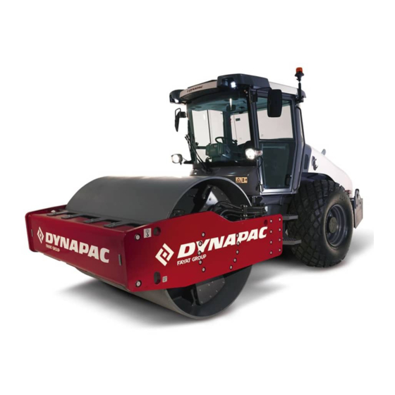
Introduction Introduction The machine Dynapac CA30D is a single drum roller in the 11 tons class respectively, with a useful drum width of 2130 mm. They are available in D (Smooth drum) and PD (padfoot) version. Intended use CA30D is commonly for compaction during work on road construction, airports, ports, and industrial areas, etc. -
Page 11: California
Introduction Only the operator is allowed to be on the roller. Make sure there is good ventilation when the engine is on in closed spaces. CALIFORNIA Proposition 65 Decal and location of decal shown in section Machine description. General This manual contains instructions for machine operation and maintenance. -
Page 12: Ce Marking And Decalaration Of Conformity
Introduction This manual contains instructions for periodic maintenance, where maintenance after every 10 and 50 hours of operation can be performed by the machine operator. Other maintenance intervals must be carried out by accredited (Dynapac) service personnel. Other instructions for the engine may be found in the manufacturer’s manual. -
Page 13: Safety - General Instructions
Safety – General instructions Safety - General instructions (Also read the safety manual) The Operator must be familiar with the contents of the OPERATION section before starting the roller . Ensure that all instructions in the MAINTENANCE section are followed. Only the operator is allowed to be on the roller. - Page 14 Safety – General instructions 14. Before repair or service: - Chock the drums/wheels. - Lock the articulation if necessary. - Please block under overhanging equipment, such as strike-off blade, edge cutter/compactor or chip spreader 15. Hearing protection is recommended if the noise level exceeds 80 dB(A). The noise level can vary depending on the equipment on the machine and the surface the machine is being used on.
-
Page 15: Safety - When Operating
Special instructions Safety – When operating Prevent persons from entering or remaining in the risk zone, i.e. a distance of at least 7 m (23 ft) in all directions from operating machines. The operator may allow a person to remain in the risk zone, however he/she must be attentive and operate the machine only when the person is fully visible or has given a clear indication of... -
Page 16: Safety (Optional)
Special instructions Safety (Optional) Air conditioning The system described in this manual is an AC/ACC type (Automatic climate control) The system contains pressurized refrigerant. It is forbidden to release refrigerants into the atmosphere. The cooling system is pressurized. Incorrect handling can result in serious personal injury. Do not disconnect or undo the hose couplings. - Page 17 Special instructions 01-06-2022 4812134740EN...
-
Page 18: Special Instructions
Special instructions Special instructions Standard lubricants and other recommended oils and fluids Before leaving the factory, the systems and components are filled with the oils and fluids specified in the lubricant specification. These are suitable for ambient temperatures in the range -15°C to +40°C (5°F -104°F). -
Page 19: High Pressure Cleaning
Special instructions High pressure cleaning Do not spray directly into electrical components. Do not use a high-pressure water jet on the instrument panel/display. Detergent that can destroy electrical parts, or which is conductive, must not be used. In certain cases there is an electrical control lever and associated electronic control unit (ECU) in the engine compartment, which must not be washed with a high-pressure jet or with any water... -
Page 20: Precaution During Welding
Special instructions Precaution during Welding When carrying out welding on the machine, the battery must be disconnected and the electronics disconnected from the electrical system. If possible, remove the part(s) to be welded from the machine. 01-06-2022 4812134740EN... -
Page 21: Battery Handling
Special instructions Battery handling When removing batteries, always disconnect the negative cable first. When fitting batteries, always connect the positive cable first. Dispose of used batteries in an environmentally friendly manner. Batteries contain toxic lead. Never use fast charge to charge the battery. This may shorten battery life. -
Page 22: Orientation Of Rotating Beacon On The Machine
Special instructions Orientation of Rotating beacon on the Machine The beacon should be fitted with then lens (amber coloured) mounted at uppermost (sky direction) i.e. never bend the beacon towards the down This will avoid rainwater entry & its accumulated through its drain holes if beacon bended at bottom. -
Page 23: Technical Specifications
Technical specifications – Noise/Vibrations/Electrical Technical specifications Noise/Vibrations Vibrations - Operator station (ISO 2631) The vibration levels are measured in accordance with the operational cycle described in EU Directive 2000/14/EC on machines equipped for the EU market, with vibration switched on, on soft polymer material and with the operator's seat in the transport position. -
Page 24: Technical Specifications - Dimensions
Technical specifications – Dimensions Technical specifications – Dimensions Dimensions – Side view Dimensions Wheelbase, drum and wheel 2990 117.7 Length, roller with standard equipment 5560 218.9 Height, with ROPS/cab (D) 2890 113.8 Height, with ROPS/cab (PD, Pad shell) 2890 113.8 Diameter, drum 1500 Thickness, drum amplitude, Nominal... -
Page 25: Dimensions - Top View
Technical specifications – Dimensions Dimensions – Top view Dimensions Front width 2256 88.8 Back width 2130 83.9 Overhang, left frame side 2.48 Overhang, right frame side 2.48 Turning radius, outside 5650 222.4 Turning radius, inside 3255 128.1 Width, drum 2130 83.9 01-06-2022 4812134740EN... -
Page 26: Technical Specifications - Weights And Volumes
Technical specifications – General Technical specifications – Weights and Volumes Weight Service Weight ROPS 11300 CA30D 11200 24912 24691 12900 CA30 PD shell 12800 28440 28219 CA30D with Pad 12100 12000 drum 26676 26455 Fluid capacities Fluid capacities D/PD Rear axle - Differential 12.5 litres... -
Page 27: Machine Speed
Technical specifications – General Centrifugal force, high amplitude (Pad Drum) 60.698 lb Centrifugal force, low amplitude (D/PD Shell) 27.651 lb Centrifugal force, low amplitude (Pad Drum) 33.721 Lb Machine Speed Propulsion PD/Pad shell Speed range Km/h (mph) 0 to 10.8 0 to 11 +/- 0.5 Speed (max.) -
Page 28: Technical Specifications - General
Technical specifications – General Technical specifications – General Engine Manufacturer/Model Cummins F 3.8 Turbo diesel engine, water-cooled Power (SAE J1995) Engine speed, idling Engine speed, loading/unloading 1,600 Engine speed, working/transport 2,200 Electrical system Battery 180Ah Alternator 135A See section “Electrical system” – fuses Fuses Tire Tire dimensions:... -
Page 29: Hydraulic System
Technical specifications – General Hydraulic System Opening pressure Drive system Supply system Vibration system Steering systems Release the brakes Air conditioning The System Described in this manual is an AC type. The System contains fluorinated greenhouse gases. Coolant designation: HFC-134a Coolant weight when full: 1.350kg -equivalent: 1.930 ton GWP : 1430... -
Page 30: Torque
Technical specifications – General Torque Tightening torque in Nm (lbf.ft) for oiled or dry bolts tightened with a torque wrench. Metric coarse screw thread, bright galvanised (fzb): STRENGTH CLASS: M – thread 8.8 – oiled 8.8 – dry 10.9 – oiled 10.9 – dry 12.9 – oiled 12.9 – dry 13.4 14.6 16.3... -
Page 31: Machine Description
Machine description Machine description Diesel engine The machine is equipped with a water-cooled, straight four cylinder, four-stroke, turbocharged diesel engine with direct injection and a charge air cooler. The engine is also equipped with Cummins® Diesel oxidation catalyst, a diesel particulate filter and a selective catalytic reduction (DOC/DPF and SCR) System for exhaust gas after- treatment. -
Page 32: Vibration System
Machine description Vibration system The vibration system is a hydrostatic system in which a hydraulic motor drives the eccentric shaft, which generates the drum's vibrations. High amplitude or low amplitude are determined by the hydraulic motor's direction of rotation. Optional systems for variable amplitude are available. -
Page 33: Machine Plate - Identification
Machine description – Stickers Machine plate – Identification 1. Product plate - Product Identification Number (PIN), model/type designation 2. Engine plate - Type description, product and serial numbers 3. Cab/ROPS plate - Certification, product and serial numbers 4. Component plate, rear axle - Product and serial numbers 5. -
Page 34: Machine Type Plate
Machine description – Stickers Machine type plate The machine type plate (1) is attached to the front left of the back frame, beside the articulated joint. The plate shows the manufacturer's name and address, type of machine, PIN (serial number), working weight, engine power and year of manufacturing. -
Page 35: Machine Description - Decals
Machine description – Stickers Machine description – Decals Location – Decals 1. Warning - Crush zone Hydraulic fluid 15. Coolant Warning, rotating engine Lift point 16. Hydraulic fluid level components 3. Warning, very hot surfaces Fixing point 17. Locking the articulation 4. - Page 36 Machine description – Stickers 10/9/17 1. Warning - Crush zone Hydraulic fluid 15. Coolant Warning, rotating engine Lift point 16. Hydraulic fluid level components 3. Warning, very hot surfaces Fixing point 17. Locking the articulation 4. Warning, ballasted tire Main switch 18.
-
Page 37: Safety Decals
Machine description – Stickers Safety decals 4700903422 Warning – Crush zone, articulation/drum. Keep a safe distance from the crush zone. 4700903423 Warning – Rotating engine components. Keep your hands at a safe distance from the danger zone. 4700903424 Warning – Hot surfaces in the engine compartment. Keep your hands at a safe distance from the danger zone. - Page 38 Machine description – Stickers Warning CALIFORNIA - Proposition 65 01-06-2022 4812134740EN...
-
Page 39: Information Decals
Machine description – Stickers Information Decals Coolant Diesel Fuel Lift point Lifting plate Manual compartment Master switch Hydraulic fluid Tire pressure Fixing point Hydraulic fluid level Fire extinguisher Grease Fuel with a low sulphur AdBlue®/DEF content Battery voltage 01-06-2022 4812134740EN... -
Page 40: Machine Description - Instruments/Controls
Machine Description – Instruments/Controls Machine Description – Instruments/Controls Locations – Instruments and controls Fig. Instruments and control panel Ignition key Keypad Emergency Stop Traffic lights Vibration Switch Hazard lights Handbook compartment Direction indicators Forward/reverse control Switch Parking brake Seat switch Display Instrument guard 01-06-2022... - Page 41 Machine Description – Instruments/Controls No. Designation Symbol Function Ignition key Positions 1-2: Shut off position, key can be removed. Position 3a: All instruments and electric controls are supplied with power. The machine is equipped with automatic glowing which occurs in this position. Position 3c: Actuation of starter motor.
- Page 42 Machine Description – Instruments/Controls No. Designation Symbol Function 10. Turn indicators, switch When pressed in one of the two directions, the (optional) respective light will blink with green illumination. In central position, the function is switched off. 11. Parking brake switch Push the button to activate the parking brake;...
-
Page 43: Functional Description - Keypad Panel
Machine Description – Instruments/Controls Functional Description – Keypad panel Working mode Amplitude, hight/low Working lights Rotating beacon High speed switch Low speed switch Engine speed selector Horn Symbol Designation Function LED colour Activates working mode, which makes it possible to use vibration and edge cutter (optional). - Page 44 Machine Description – Instruments/Controls Symbol Designation Function LED colour Press to activate the rotating beacon Rotating beacon LED OFF → (Option) LED LEFT → On Yellow LED OFF → Working mode Low speed switch LED LEFT → Tortoise mode on the drum Activate the change function of the machines LED OFF Hi speed switch...
-
Page 45: Functional Description - Display
Machine Description – Instruments/Controls Functional Description – Display When the ignition key is activated to position 1, the start screen appears on the display (Fig. 1). This is shown for a two seconds and then switches over to the status screen. Fig. -
Page 46: User Setting
Machine Description – Instruments/Controls Transport with machine speed (Applicable to DCM) User can see the machine speed (12) in travel and working mode. It’s applicable in DCM machine. User settings Users can change the lighting configurations (6), Brightness & contrast. Machine speed (7) Applicable in Compaction meter. SW: - 4812133751–... -
Page 47: Sub Menu - Error Code
Machine Description – Instruments/Controls Sub menu – Error codes 1. The alarm symbols are shown on the left hand side of the display. At the top is the red warning symbol and at the bottom the yellow (1). 2. The side menu is displayed, when the sub-menu is selected. Fig. - Page 48 Machine Description – Instruments/Controls Functional Description – Tell- Tales & Alarms W n ng D gn t n F nct n Warning symbol, When Hydraulic fluid filter clogged; hydraulic fluid immediately symbol will come & the filter hydraulic fluid filter must be changed.
- Page 49 Machine Description – Instruments/Controls W n ng D gn t n F nct n Warning symbol, If this symbol is shown, the engine's oil low oil pressure, pressure is too low. diesel engine Switch off the engine immediately & fix it. Warning symbol, If this symbol is shown, the engine must water in the fuel...
- Page 50 Machine Description – Instruments/Controls W n ng D gn t n F nct n The High Exhaust System Warning symbol, Temperature (HEST) Lamp will HEST (High Exhaust illuminate during manual (non- System mission) exhaust system cleaning. Temperature) In addition, the HEST Lamp will also illuminate if the exhaust temperature exceeds the calibrated temperature threshold.
- Page 51 Machine Description – Instruments/Controls W n ng D gn t n F nct n Parking brake When the parking brake applied symbol should come red tell- tale When the parking brake released Parking Brake and try to start the machine, symbol should appear to indicate the Parking switch need to applied in machine starting...
- Page 52 Machine Description – Instruments/Controls W n ng D gn t n F nct n Switched ‘ON’ Low speed button Symbolic and check symbol as per beside representation with tortoise curve inside the of working mode drum (this will appear when low speed activated) Switched ‘ON’...
- Page 53 Machine Description – Instruments/Controls W n ng gn t n F nct n “Exhaust Cleaning” "MACHINE SETTINGS” Normally not necessary always to use. Initiate cleaning can be used if the Exhaust System Cleaning Lamp/Popup is shown in the display as per beside snap.
-
Page 54: Instruction And Control, Cab
Machine Description – Instruments/Controls Instruments and control, Cab No. Designation Symbol Function AC/Heater control Turn to right increase heating. Turn to centre reduce heating. Turn to left Increase the cooling. Ventilation fan, Switch In the left position, the fan is off. Turning the knob to the right increases the volume of air entering the cab Air conditioning switch... - Page 55 Machine Description – Instruments/Controls Front and rear windshield Press the button on top to activate the front windshield washers switch washers. Fuse box Contains fuses for the electrical system in the cab. 14. Air vents Position the air vents in the best way for you. 15.
-
Page 56: A/C - System Operation
Machine Description – Instruments/Controls A/C – System operation Introduction This air conditioning system was designed to provide safety and comfort for the equipment operator while working, consequently improving productivity. Using the cab Controls Defroster To Quickly remove ice or mist, make sure that only the front and rear air nozzle are open. -
Page 57: Electronic Control Unit
Machine description – Electrical system Electronic control unit The electronic control unit (ECU) (14) is place behind Left side the operator’s seat. The ECU controls, Vibration, Engine, start-stops & machine safety interlocks. Fig. Driving compartment 14. Control unit (ECU) 15,16,17 Main fuses There are three main fuses These are on the battery... -
Page 58: Relays
Machine description – Electrical system Relays The table below shows fuse amperage and function. Fig. Relays and fuse board Fuse Amperage Function Spare Spare Display, Keypad, Dyn@link, P-Brake Switch Neutral switch, Seat switch, alternator, vibration switch (joystick) Compaction Meter (Option) Front Working Lights Relay Rear Working Lights Relay Line heater relay... -
Page 59: Operation - Start-Up
Operation – Start-up Operation – Start-up Before starting Master switch – Activation Always perform daily maintenance. See the maintenance instructions. The battery master switch is located in the engine compartment. Open the engine cover and set the key (20) to the ON position. The whole circuit of the machine gets electric power. -
Page 60: Before Starting
Operation – Start-up Before starting Make sure that the emergency stop (2) is pulled out. When the roller is in neutral or there is no load on the operator's seat, the automatic brake function is engaged. Fig. Instrument panel: Pull out the emergency stop (2). Emergency stop;... -
Page 61: View
Operation – Start-up View Before starting, make sure that the view forwards and backwards is unobstructed. All cab windows must be clean and rear-view mirrors properly adjusted. Interlock The machine is equipped with a locking system. The engine switches off 4 seconds after the operator rises from the seat at the same time as the forward/reverse lever Fig. -
Page 62: Operation - Start-Up
Operation – Start-up Operation – Start-up Start of diesel engine Make sure that the emergency stop (2) is pulled out. Make sure that the parking brake switch (12) is activated. Set the forward/reverse lever (5) in neutral. The engine can only be started when the lever is in neutral. -
Page 63: Operation - Driving
Operation - Driving Operation – Driving Operating the roller The machine should never be controlled from the ground. The operator should remain seated at all times. Set speed selector (26) in high operation position. Release the parking brake (12). Fig. Control panel: Check that the steering is working properly by turning the Ignition key;... -
Page 64: Operation - Vibration
Operation - Vibration Operation – Vibration Vibration switch To activate or deactivate the vibration, activate the high or low amplitude selector (8). The operator should activate it using the vibration switch, located under the forward/reverse lever (5). Fig. Control panel: Amplitude switch. -
Page 65: Dynapac Compaction Meter (Dcm) Including Dynapac Bouncing Control (Dbc) - Optional
Operation - Vibration Dynapac Compaction Meter (DCM) including Dynapac Bouncing Indication (DBI) – Optional The Compaction Meter is an accessory used to improve compaction efficiency and efficacy. Its system allows to choose different types of materials as a parameter, adapting the system to the material being compacted. If the machine is equipped with the meter, an extra display indicates the stiffness of the surface as CMV (compaction meter value). - Page 66 Operation - Vibration Some reference CMV for some compacted materials: Material Rockfill 40 - 200 Rock fill 25 - 100 Sand 20 - 60 Silt 5 -30 Clay 0 - 80 The water content in the compacted soil, except for rockfill, has a large influence on stiffness;...
-
Page 67: Operation - Stopping
Operation – Stopping Operation – Stopping Braking Service brake Press the switch (3) to switch off the vibration. Place the forward/reverse lever (5) to neutral position to stop the machine. Set Throttle control to idle running position. Set the parking brake switch in the ‘ON’ position. Always use the parking brake when the machine is stationary on a sloping surface. -
Page 68: Switching Off
Operation – Stopping Switching off Check the controls and warning lights to see if any faults are indicated (29). Switch off all lights and other electrical functions. Set Speed selector (26) in low idle position and let the engine run for about one minute. Activate the parking brake (12). -
Page 69: Long-Term Parking
Long-term parking Long-term Parking The following instructions should be followed for long-term parking (more than one month). These measures apply when parking for a period of up to 6 months. Wash the machine and touch up the paint finish to avoid rusting. -
Page 70: Hoods, Tarpaulin
Long-term parking Hoods, tarpaulin Place the control cover over the control panel. Cover the whole machine with protective tarpaulin. A gap must be left between the tarpaulin and the ground. If possible, store the machine indoors and ideally in a building where the temperature is constant. -
Page 71: Miscellaneous
Miscellaneous Miscellaneous Lifting Locking the steering articulation Steering articulation must be locked to prevent inadvertent turning before lifting the machine. Turn the steering wheel so the direction is straight forward. Press the emergency/parking brake button. Pull out the lowermost safety pin with a wire (35). Fig. -
Page 72: Unlocking The Articulation
Miscellaneous Unlocking the articulation Remember to unlock the articulation before the start of operation. Fold the locking arm (31) back and secure it in the locking articulation (33) with the locking pin (30). Install the safety pin with the cable (31) to attach the locking pin (32). The locking articulation (33) is located on the frame of the machine. -
Page 73: Towing The Roller
Miscellaneous Towing the Roller When the roller is towed/recovered, the towing vehicle will have to break it. If necessary, use a towing bar, since the machine will have no breaks. The machine has to be towed slowly at a max. speed of 3 km/h (2 mph), and only for short distances, of max. -
Page 74: Securing In Closed Container For Loading
Miscellaneous Securing in closed Container for loading Securing the CA30D/PD Vibratory roller from Dynapac for transport. 1 – 3= Double lashing, i.e one lashing with two parts secured to two different lashing mounts, symmetrically located on the right and left sides. 4 –... -
Page 75: Operating Instructions - Summary
Operating instructions - Summary Operating instructions – Summary 1. Follow the SAFETY INSTRUCTIONS specified in the safety manual; 2. Make sure that all instructions in the MAINTENANCE section are followed; 3. Activate the battery switch; 4. Set the forward/reverse lever in neutral; 5. -
Page 76: Preventive Maintenance
Preventive maintenance Preventive maintenance Complete maintenance is necessary for the machine to function satisfactorily and at the lowest possible cost. The Maintenance section includes periodic maintenance that must be carried out on the machine. The recommended maintenance intervals assume that the machine is used in a normal environment and working conditions. -
Page 77: Maintenance - Lubricants And Symbols
Maintenance – Lubricants and symbols Maintenance – Lubricants and symbols Always use high-quality lubricants in the recommended amounts. Too much grease or oil can cause overheating, resulting in premature wear. Ambient temperature 0°C +50°C Shell Rimula R4L 15W40, API CJ4 or CK4 PN 4812161855 –... -
Page 78: Maintenance Symbols
Maintenance – Lubricants and symbols Maintenance symbols Engine, oil level Tire pressure Engine, oil filter Air cleaner Hydraulic reservoir Battery Hydraulic fluid, filter Recycling Transmission, oil level Fuel filter Drum, oil level Coolant Oil for lubrication Urea (DEF) 01-06-2022 4812134740EN... -
Page 79: Maintenance - Planned Maintenance
Maintenance – Planned maintenance Maintenance – Planned maintenance Service and inspection points Carefully read this section of the manual before performing any maintenance service or lubrication of the machine. Get in the habit of examining the areas around and under the equipment. -
Page 80: Scheduled Maintenance And Lubrication
Maintenance – Planned maintenance Scheduled maintenance and lubrication The maintenance and lubrication services should be performed firstly based on the number of operation hours, and secondly, based on periods of time such as days, weeks, etc. Always clean around covers, caps, fittings or plugs before opening them or applying grease. -
Page 81: Service And Maintenance Point
Maintenance – Planned maintenance Service and maintenance point Check the Dobbs meter on the machine to know what type of maintenance is needed. Every 10 hours of operation (Daily) Refer to the contents to find the page number of the sections referred to ! Pos. -
Page 82: Every 250/750/1250/1750 Hours Of Operation (Monthly)
Maintenance – Planned maintenance Change oil in the rear axle planetary gearing Change the oil in the gearbox Steering Hitch tightening Every 250/ 750/ 1250/ 1750 hours of operation (Monthly) Refer to the contents to find the page number of the sections referred to ! Pos. -
Page 83: Every 1000 Hours Of Operation (Every Six Months)
Maintenance – Planned maintenance Every 1000 hours of operation (Every six months) Refer to the contents to find the page number of the sections referred to ! Pos. in Action Comment Replace the air cleaner's main filter and backup filter Change the hydraulic fluid filter Drain the condensate from hydraulic reservoir Drain condensate from fuel tank... - Page 84 Maintenance – Planned maintenance Check belt tension for Engine drive Refer to the engine manual system Steering Hitch tightening Cleaning the ventilation screws in the drum cartridges Drum cartridge – oil level glass change Replace the filter in Urea tank Replace the filter in Urea pump 01-06-2022 4812134740EN...
-
Page 85: Every 10 Hours Of Operation (Daily)
Maintenance – Planned maintenance Maintenance, 10h Every 10 hours of operation (Daily) Park the roller on a level surface. When checking and making adjustments, the engine should be switched off and the emergency/parking brake should be applied, if not otherwise specified. Ensure that there is good ventilation (air extraction) if the engine is run indoors. -
Page 86: Air Circulation
Maintenance – Planned maintenance Air circulation Ensure that the engine has free circulation of cooling air through the protective grille in the hood. To open the engine hood, turn the hood latch (1) upward. Raise the hood to its fully open position, checking that the red safety catch on the left gas spring is latched. -
Page 87: Fuel Tank Filling
Maintenance – Planned maintenance Fuel tank – Filling Refuel daily with diesel fuel up to the lower edge of the filler pipe (1). Follow the engine manufacturer’s specifications with respect to fuel quality. Stop the engine. Short-circuit the filler gun against a non-insulated part of the machine before refuelling, and against the filler pipe (1) while refuelling. -
Page 88: Emergency Stop
Maintenance – Planned maintenance Emergency stop Drive the machine slowly forward. Hold the steering wheel firmly and brace yourself for a sudden stop. Press the emergency stop (1). The machine will stop abruptly and the engine will be switched off. After testing the brakes, set the forward/reverse lever in neutral. -
Page 89: Urea Tank - Refilling
Maintenance – Planned maintenance Urea tank – Refilling Top up the urea tank every day. Follow the engine manufacturer's specifications for urea usage The urea solution must only be filled in the tank provided for this. Accidentally filling the tank with another operating medium (e.g. -
Page 90: Maintenance 50 Hrs
Maintenance – Planned maintenance Maintenance - 50h Every 50 hours of operation (Weekly) Park the roller on a level surface. When checking and making adjustments, the engine should be switched off and the emergency/parking brake should be applied, if not otherwise specified. Ensure that there is good ventilation (air extraction) if the engine is run indoors. -
Page 91: Air Cleaning
Maintenance – Planned maintenance Air cleaner – Cleaning Wipe the inside of the cover and filter housing. Wipe also both surfaces of the outlet pipe. Check that the hose clamps between the filter housing and the suction hose are tight and that the hoses are intact. -
Page 92: Tire - Air Pressure - Wheel Nut - Tightening
Maintenance – Planned maintenance Tires – Air pressure – Wheel nuts – Tightening Check the tire pressures using a pressure gauge. When the tire is filled with fluid, the valve (1) should be positioned at “12 o’clock”, once the specified pressure is reached. -
Page 93: Maintenance First 50 Hours
Maintenance – Planned maintenance Maintenance – First 50h Park the roller on a level surface. When checking and making adjustments, the engine should be switched off and the emergency/parking brake should be applied, if not otherwise specified. Ensure that there is good ventilation (air extraction) if the engine is run indoors. -
Page 94: Rear Axle Differential - Change The Oil
Maintenance – Planned maintenance Rear axle differential – Change oil level Do not work under the roller with the engine running. Park on a level surface. Clean and remove the three filler/level plugs (1) and (3) and the three drain plugs (2). The filler/level plugs are located in the front and back of the axle and the drain plugs are located on the lower and back part. -
Page 95: Drum Gearbox (D/Pd) - Change The Oil
Maintenance – Planned maintenance Drum gearbox (D/PD) – Changing the oil Wipe clean, unscrew the plugs (1, 2 and 3) and drain the oil into a suitable receptacle with a capacity of about 5.0 litres (5.3 qts). Refit the drainage plug (1) and top up with oil up to the level plug (3). -
Page 96: Maintenance 250/750/1250/1750 Hrs
Maintenance – Planned maintenance Maintenance – 250/750/1250/1750h Park the roller on a level surface. When checking and making adjustments, the engine should be switched off and the emergency/parking brake should be applied, if not otherwise specified. Ensure that there is good ventilation (air extraction) if the engine is run indoors. -
Page 97: Drum - Checking The Oil Level
Maintenance – Planned maintenance Drum – Checking the oil level Place the roller on a level surface so that the plug (1) and the drum's number plate are visible on the right side. The oil level should now reach the sight glass (3). If necessary, remove the plug (1) and fill to halfway up the sight glass. -
Page 98: Bolted Joints - Checking Tightening
Maintenance – Planned maintenance Bolted joints – Checking tightening Steering pump for the diesel engine (1) 55 Nm, lightly oiled. Rear axle suspension (2), 330 Nm (243 ft/lbf) oiled. Engine shock mount (3). Check that all the M12 bolts (20 pieces) are tightened with 70 Nm and lightly oiled. -
Page 99: Check Battery Cell
Maintenance – Planned maintenance Check – Battery cell Take off the cap (1) and make sure that electrolyte level (2) is about 10 mm above the plates. If the level is lower, top up to the correct level with distilled water. If the ambient temperature is below freezing, run the engine for a while after topping up with distilled water. -
Page 100: Maintenance 500/1500 Hrs (Every Three Months)
Maintenance – Planned maintenance Maintenance – 500/1500h Park the roller on a level surface. When checking and making adjustments, the engine should be switched off and the emergency/parking brake should be applied, if not otherwise specified. Ensure that there is good ventilation (air extraction) if the engine is run indoors. -
Page 101: Hydraulic Reservior-Bleeder Filter Check
Maintenance – Planned maintenance Hydraulic reservoir – bleeder filter check If passage in either direction is blocked, clean the filter with a little diesel oil and blow through with compressed air until the block is removed, or replace the cap with a new one. Always wear protective goggles when working with compressed air. -
Page 102: Maintenance 1000Hrs (Every Six Months)
Maintenance – Planned maintenance Maintenance - 1000h Park the roller on a level surface. When checking and making adjustments, the engine should be switched off and the emergency/parking brake should be applied, if not otherwise specified. Ensure that there is good ventilation (air extraction) if the engine is run indoors. -
Page 103: Draining The Hydraulic Fluid Filter
Maintenance – Planned maintenance Draining the hydraulic fluid tank Condensate in the hydraulic tank is drained via the plug (2). Drainage must be performed when the machine has been stationary for an extended period, e.g. overnight. Drain as follows: Remove the plug (2); Place an empty container under the Knob;... -
Page 104: Rear Axle Differential - Change The Oil
Maintenance – Planned maintenance Rear axle differential – Oil change Do not work under the machine with the engine running. Park on a level surface. Lock the wheels. Clean and remove the three filler/level plugs (1) and (3) and the three drain plugs (2). The filler/level plugs are located in the front and back of the axle and the drain plugs are located on the lower and back part. -
Page 105: Diesel Engine - Oil And Filter Change
Maintenance – Planned maintenance Diesel engine – Oil and filter change Take great care when draining fluid and oil at high temperatures. Wear protective gloves and goggles. It is easier to handle the oil drain plug (1) from under the engine. -
Page 106: Belt Tension Check Engine Drive System
Maintenance – Planned maintenance Check the engine belt tension Check positioning of the belt on the tensioner, which should be centred, and if the belt shows signs of too much wear, it should be replaced. Check the engine manual for more information. Fig. -
Page 107: Maintenance 2000Hrs (Yearly)
Maintenance – Planned maintenance Maintenance - 2000h Park the roller on a level surface. When checking and making adjustments, the engine should be switched off and the emergency/parking brake should be applied, if not otherwise specified. Ensure that there is good ventilation (air extraction) if the engine is run indoors. -
Page 108: Control - Lubrication
Maintenance – Planned maintenance Controls – Lubrication Lubricate the forward/reverse throttle mechanism. Remove the external cover at the bottom of the seat by loosening the screws (2). Lubricate the drive elements. Fig. Forward/reverse control Screws Automatic Climate Control Regular inspection and maintenance are necessary to ensure satisfactory long term operation. -
Page 109: Fuel Filter Replacement
Maintenance – Planned maintenance Fuel filter replacement Remove the threaded fuel filter (1) using the filter wrench. Lubricate the O ring with clean lubricating oil. Do not prefill the engine fuel filter. Install the filter on the filter head. Press the filter until the seal touches the surface of the filter head. -
Page 110: Change The Hydraulic Fluid Filter
Maintenance – Planned maintenance Change the hydraulic fluid filter Always wear protective goggles when working with compressed air. Carefully clean around the hydraulic filter. Remove the filter (1) and take to an environmentally- compliant waste disposal station. The filter is of the disposable type and cannot be cleaned. -
Page 111: Rear Axle Differential - Oil Change
Maintenance – Planned maintenance Rear axle differential – Oil change Do not work under the machine with the engine running. Park on a level surface. Lock the wheels. Clean and remove the three filler/level plugs (1) and (3) and the three drain plugs (2). The filler/level plugs are located in the front and back of the axle and the drain plugs are located on the lower and back part. -
Page 112: Steering Hitch - Tightening
Maintenance – Planned maintenance Steering hitch – Tightening The easiest way to identify if you have this type of steering hitch is that it has a new type of nut (1) at the top as shown. Actual torque (Nm) should be when the machines position is straight ahead 270 Nm Drum cartridge - Cleaning the ventilation screw... -
Page 113: Replacing The Urea Pump Filter
Maintenance – Planned maintenance Replacing the urea tank suction filter The urea tank is located on the right side of the machine. Loosen and remove the tank multifunction unit (1), then remove the suction filter (2) that is located in the bottom of the unit. - Page 114 Dynapac Road Construction Equipment (India) Pvt. Ltd. Plot no 01, Gat no. 163-168, Alandi Markal road, Village: Fulgaon, Taluka: Haveli, Dist: Pune- 412216, India www.dynapac.com...
Need help?
Do you have a question about the Dynapac CA30D and is the answer not in the manual?
Questions and answers