
Subscribe to Our Youtube Channel
Related Manuals for Micromeritics AccuPyc 1330


Summary of Contents for Micromeritics AccuPyc 1330
- Page 1 AccuPyc 1330 Pycnometer Operator’s Manual V3.03 Part No. 133-42808-01 January 2005...
- Page 2 AccuPyc is a trademark of Micromeritics Instrument Corporation. ©Micromeritics Instrument Corporation 2005. All rights reserved. The software described in this manual is furnished under a license agreement and may be used or copied only in ac- cordance with the terms of the agreement.
- Page 3 MICROMERITICS shall not be liable for consequential or other type damages resulting from the use of any of its products other than the liability stated above. This warranty is in lieu of all other warranties, express or implied, including, but not limited to the implied warranties of merchantability or fitness for use.
-
Page 4: Table Of Contents
Unpacking and Inspection ......2-1 Lifting the Accupyc 1330 ......2-1 Unpacking the Cartons . - Page 5 Table of Contents AccuPyc 1330 Entering Commands ......4-5 Performing an Analysis ......4-6 Reviewing and Editing Data .
-
Page 6: Organization Of The Manual
CHAPTER 1 GENERAL INFORMATION • Organization of the Manual • Conventions • Equipment Description... - Page 7 AccuPyc 1330 Organization of the Manual GENERAL DESCRIPTION Organization of the Manual This manual describes how to install, operate, and maintain the AccuPyc 1330 Pycnometer. The manual is divided into six chapters. Chapter 1 Provides a general description and specifications of the pycnometer.
-
Page 8: Equipment Description
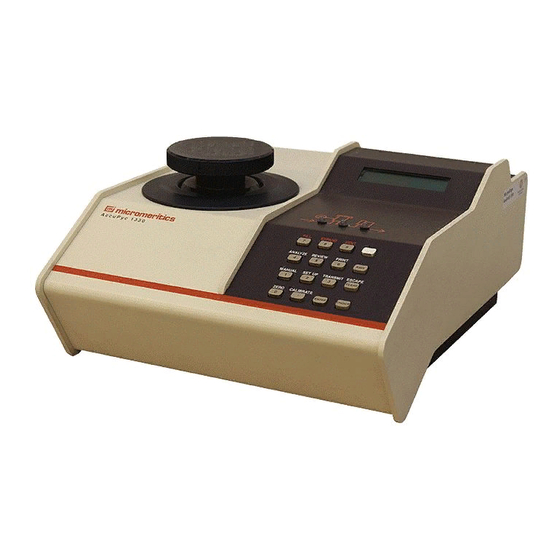
Equipment Description AccuPyc 1330 Equipment Description The AccuPyc 1330 Pycnometer is an easy-to-use, fully-automatic gas displace- ment pycnometer. Analyses are initiated with a few keystrokes. Once an analy- sis is initiated, data are collected, calculations performed, and results displayed without further operator intervention. The pycnometer may be oper- ated in any of five languages: English, French, German, Italian, or Spanish. - Page 9 AccuPyc 1330 Equipment Description Cell Chamber Expansion Chamber Expansion Fill Valve Vent Valve Valve Indicator Indicator Indicator Figure 1-2. Schematic Diagram In addition to analysis, there are two other automatic operations performed by the pycnometer: calibration and transducer zero reset.
-
Page 10: Pycnometer Keypad
Equipment Description AccuPyc 1330 Pycnometer Keypad FILL EXPAND VENT PRINT ANALYZE REVIEW SAVE SETUP MANUAL TRANSMIT ESCAPE CLEAR ZERO CALIBRATE • ENTER CHOICE Figure 1-3. Pycnometer Keypad Most keys on the keypad perform one primary and one alternate function. The primary function of any key is indicated by the number or command on the face of the key. - Page 11 AccuPyc 1330 Equipment Description Tables 1-1 and 1-2 describe how the keys are used to control and monitor the pycnometer. Table 1-1. Standard Keys Used To Enter the numbers 0 through 9. • Enter a decimal point, a dash for sample ID, a slash for date, or a colon for time.
- Page 12 Equipment Description AccuPyc 1330 Table 1-2. Key Combinations Function Keys Used To ZERO Zero the pressure transducer. • CALIBRATE Calibrate the pycnometer. MANUAL Manually control the valves. After pressing the Manual key, you may use the FILL, EXPAND, and VENT commands to open and close the valves.
-
Page 13: Specifications
AccuPyc 1330 Specifications Specifications Table 1-3. AccuPyc 1330 Pycnometer Specifications Characteristic Specification Stable between 15 and 35 °C (59 to 96 °F) Temperature Humidity 20 to 80% relative, non-condensing Voltage 90 to 264 VAC Power 30 VA Frequency 50/60 Hz Sample Volume 0.5 - 100 cm... -
Page 14: Installation
CHAPTER 2 INSTALLATION • Unpacking and Inspection • Selecting the Location • Gas Requirements • Equipment Setup • Verifying Operation... -
Page 15: Lifting The Accupyc 1330
Pycnometer. Unpacking and Inspection Lifting the Accupyc 1330 The Accupyc 1330 can be lifted by one person using two hands placed on op- posite sides of the instrument. As always, proper lifting techniques should be used to prevent injury. Unpacking the Cartons... - Page 16 Make reference to the sales order or purchase order for the equipment, and provide the date the equipment was received. Notify a Micromeritics Service Representative of the defect and request shipping instructions. The Service Department will assign a Return Mate- rial Authorization (RMA) number to your return and provide shipping in- formation.
-
Page 17: Equipment Setup
AccuPyc 1330 Equipment Setup Equipment Setup The pycnometer should be checked to make sure it is operating properly be- fore actual analyses are attempted. The remainder of this chapter describes how to install the pycnometer and verify operation. Selecting the Location When selecting the location of the pycnometer, keep the following in mind: The pycnometer performs best in a constant temperature environment. -
Page 18: Rear Panel Connections
Equipment Setup AccuPyc 1330 Rear Panel Connections Attach an appropriate regulator to the gas supply cylinder. Leave the gas cylinder shut-off valves closed until instructed otherwise. Cylinder Shut-Off Two-Stage Valve Pressure Reducing Regulator Shut-Off Valve Nut Gas Cylinder Regulator Shut-Off Valve... - Page 19 AccuPyc 1330 Equipment Setup Software Card Printer Printer Connector AccuPyc 1330 Pycnometer Inlet RS-232 Vent Flexible Tubing (optional) To Power Source Gas Cylinder Figure 2-8. Rear Panel Connections Turn the nut on the tubing clockwise until it is finger-tight. Then use a 7/16-in.
- Page 20 OFF (O). Do NOT install or remove the software card while the power is turned ON. 11. Hold the AccuPyc 1330 Software Card with the label facing up. Insert the card (notched end first) into the connector on the rear panel of the pycnometer and press firmly to lock into place.
-
Page 21: Turning On The Pycnometer
AccuPyc 1330 Equipment Setup Turning On the Pycnometer To turn on the pycnometer, place the power ON/OFF switch on the rear panel in the ON ( | ) position. The system is automatically vented and the fol- lowing prompt is displayed:... -
Page 22: Entering Report And Analysis Parameters
Equipment Setup AccuPyc 1330 Entering Report and Analysis Parameters The pycnometer is shipped with the following default values for analysis pa- rameters: Number of purges Purge fill pressure 19.5 psig Number of runs Run fill pressure 19.5 psig Equilibration rate 0.005 psig/min... -
Page 23: Selecting Units Of Pressure Measurement And Operating Language
AccuPyc 1330 Equipment Setup Selecting Units of Pressure Measurement and Operating Language The units of measurement for pressure may be displayed in pounds-per- square-inch gauge (psig) or kilopascal gauge (kPag). In this manual, psig is used in the examples shown. The pycnometer may be operated in any of five languages: English, French, German, Italian, or Spanish. -
Page 24: Greasing The Chamber Cap O-Ring
Equipment Setup AccuPyc 1330 Greasing the Chamber Cap O-Ring A greasing disk is included in the accessory kit shipped with the pycnometer. Use the disk to grease the O-ring as described below. Rubber gloves should be worn to prevent contaminating the grease with oil from your fingertips. -
Page 25: Verifying Operation
If the pycnometer responds as described above, it is ready to operate. If it does not, check installation procedures, then repeat the verification proce- dures. If it still does not respond as described above, service to the system or operational assistance may be required. Contact a Micromeritics Service Rep- resentative. September 1996... -
Page 26: Setting Regulator Pressure
CHAPTER 3 PERFORMING AN ANALYSIS • Setting Regulator Pressure • Preparing and Loading a Sample • Starting the Analysis • Viewing or Printing Analysis Results... - Page 27 PERFORMING AN ANALYSIS This chapter briefly describes how to perform an analysis. Chapter 4 de- scribes in detail how to use all the functions of the AccuPyc 1330 Pycnometer. The cell chamber and cap must be kept clean at all times. Particles on the cap seating surface, in the sample cup, under the sample, or clinging to the sample chamber wall may cause inaccurate results.
- Page 28 Preparing and Loading a Sample AccuPyc 1330 Preparing and Loading a Sample Preparing the sample is the first step in obtaining accurate results from the pycnometer. Samples must be free of moisture in order to obtain true sample weight and to avoid the distorting effect of water vapor on the volume meas- urement.
- Page 29 AccuPyc 1330 Preparing and Loading a Sample Remove the cell chamber cap. When you remove the chamber cap, place it on a clean, dry surface with the greased side down so that particles will not accumulate on the greased surface. If the cap is placed on a dirty surface, analysis errors may result.
- Page 30 Starting an Analysis AccuPyc 1330 Starting an Analysis Using the Default Parameters To start an analysis using the analysis and report parameters shipped with the pycnometer: Press The following prompt is displayed: [Enter] to start [Escape] to cancel Press to begin the analysis.
- Page 31 AccuPyc 1330 Starting an Analysis The following prompt is displayed. [Enter] to start Press to begin the analysis. ENTER Viewing or Printing Analysis Results As the analysis is performed, operational status messages are displayed. (Refer to Monitoring the System in Chapter 4 for a description of the messages.)
- Page 32 CHAPTER 4 GENERAL OPERATING INSTRUCTIONS • Monitoring the System • Canceling an Automatic Operation • Entering Commands • Printing Reports • Transmitting Reports • Calibrating the Pycnometer • Zeroing the Pressure Transducer • Manually Controlling the Valves • Editing the Setup Parameters...
- Page 33 AccuPyc 1330 Monitoring the System GENERAL OPERATING INSTRUCTIONS The pycnometer remains in the display mode until you enter a command by pressing the appropriate keys. This chapter describes how to read the display and enter commands. Keep the cap on the cell chamber except when actually inserting or re- moving a sample.
- Page 34 Monitoring the System AccuPyc 1330 Table 4-1. Automatic Operation Status Messages Abbreviation Item Description Displayed Operation Type Anls Analysis Cal 1 Calibration Pass 1, which is the first pass during calibration with the cell chamber empty. Cal 2 Calibration Pass 2, which is the...
- Page 35 AccuPyc 1330 Monitoring the System Error and Report Messages Error and report messages generated during the operation are placed in a queue in chronological order, with error messages having the highest priority (refer to Figure 4-1). When the automatic operation is complete, the Reload prompt is displayed.
- Page 36 Canceling an Automatic Operation AccuPyc 1330 Canceling an Automatic Operation You may cancel an automatic operation that is in progress by pressing . The following message is displayed: CLEAR Press ENTER to cancel automatic operation Press within five seconds to cancel the operation.
- Page 37 AccuPyc 1330 Entering Commands Entering Commands The pycnometer remains in display mode until you enter a command by pressing the appropriate keys on the keypad. Commands start an analysis or other automatic operations and allow you to modify operating parameters.
- Page 38 Performing an Analysis AccuPyc 1330 Performing an Analysis Press to perform an analysis. Display Entry This prompt is displayed only when Sample ID: Sample ID was enabled in the Set-Up function (refer to Report Options later in this chapter). The sample ID can contain from 1 to 20 numbers and dashes.
-
Page 39: Reviewing And Editing Data
AccuPyc 1330 Reviewing and Editing Data Reviewing and Editing Data The Review function enables you to review and edit the results of the last analysis or calibration along with its entered parameters. Reviewing and Editing Analysis Results and Parameters Press to review or edit analysis results. - Page 40 Reviewing and Editing Data AccuPyc 1330 Either density or volume is displayed Den [N] = (density) depending on the selection made for Dev [N] = (deviation) display mode (refer to Report Options). [N] is replaced with the number of the run.
-
Page 41: Reviewing And Editing Calibration Results And Parameters
AccuPyc 1330 Reviewing and Editing Data Reviewing and Editing Calibration Results and Parameters Press to review or edit calibration results. Display Entry The volume of the calibration standard is Cal std volume: displayed. (volume) Select either cell chamber or expansion... -
Page 42: Printing Reports
Printing Reports AccuPyc 1330 Printing Reports Reports are generated after analysis and calibration and remain available for viewing or printing until another automatic operation (other than zero) is per- formed. When you perform an automatic operation, reports from the previous operation are deleted. - Page 43 AccuPyc 1330 Printing Reports The following is a calibration report. The calibration standard used must be at least 10% of nominal cell volume. We recommend 60 to 70% for the best results. Figure 4-1. Calibration Report September 1996 4-11...
- Page 44 Printing Reports AccuPyc 1330 The following report represents an analysis that was performed on the calibra- tion standard used for the previous report. Figure 4-2. Analysis Report 4-12 September 1996...
- Page 45 AccuPyc 1330 Printing Reports The following report represents an analysis that was performed on an un- treated (not dried) sample with run precision enabled. The run precision fea- ture eliminates data from all but five runs that are within a specified tolerance.
-
Page 46: Transmitting Reports
Transmitting Reports AccuPyc 1330 Transmitting Reports The AccuPyc RS-232 interface transmits report data to a computer using the standard ASCII file format. Once captured with an asynchronous serial com- munications program such as COTERM, which is available from Mi- cromeritics (part no. 003-20632-00), the report data can be used in popular spreadsheet and data manipulation programs. -
Page 47: Calibrating The Pycnometer
AccuPyc 1330 Calibrating the Pycnometer Calibrating the Pycnometer You should check or calibrate the pycnometer anytime you restart it. For a quick check, run an analysis with an empty cup to see how close the average volume is to 0. It should be ±0.05% of full-scale. If it is not within ±0.05% of full-scale, calibrate according to the instructions given below. -
Page 48: Zeroing The Pressure Transducer
Zeroing the Pressure Transducer AccuPyc 1330 Zeroing the Pressure Transducer The transducer offset may be reset to zero in order to perform diagnostics or to operate the pycnometer manually. The transducer is automatically set to zero for each run in an analysis or calibration. -
Page 49: Manually Controlling The Valves
AccuPyc 1330 Manually Controlling the Valves Manually Controlling the Valves This function enables you to perform a manual analysis by controlling the valves. Press to enter manual mode. Display Entry When Manual is shown in the display, you Manual can manually open and close the fill,... -
Page 50: Editing The Setup Parameters
Editing the Setup Parameters AccuPyc 1330 Editing the Setup Parameters The set-up function enables you to enter parameters to be used for analysis, calibration, reporting, and data transmission. There are five sets of parameters: Analysis or calibration parameters Report options... -
Page 51: Analysis Or Calibration Parameters
AccuPyc 1330 Editing the Setup Parameters Analysis or Calibration Parameters Press to display or edit analysis or calibration parameters. Display Entry Press until Analysis parameters is CHOICE Set-up type? displayed. Then press ENTER Analysis parameters Enter the number of purges to be performed... - Page 52 Editing the Setup Parameters AccuPyc 1330 Display Entry Enter the equilibration rate and press ENTER Equilibration rate: 0.005 psig/min Range: 0.0001 to 9.0000 psig/min 0.0007 to 62.05 kPag/min A high rate will produce faster results, but results may not be as precise as desired.
- Page 53 AccuPyc 1330 Editing the Setup Parameters Display Entry This prompt is displayed only if the number Percent full-scale: of runs is greater than five. 0.05% Enter the run precision volume tolerance which is expressed as a percent of nominal cell volume, then press...
-
Page 54: Report Options
Editing the Setup Parameters AccuPyc 1330 Report Options Press to display or edit report options. Display Entry Press until Report options is CHOICE Set-up type? displayed. Then press ENTER Report options Select the mode, either density or volume, Anls display mode? - Page 55 AccuPyc 1330 Editing the Setup Parameters Display Entry A display report is always calculated regardless of the destination. Choose one of the following options: Set-up type? Report options Press to save the information you SAVE entered and return to display mode.
-
Page 56: Calibration Data
Editing the Setup Parameters AccuPyc 1330 Calibration Data Press to display or edit calibration data. Display Entry Press until Calibration data is CHOICE Set up type? displayed. Then press ENTER Calibration data When the pycnometer is calibrated, cell volume and expansion volume are updated automatically. - Page 57 AccuPyc 1330 Editing the Setup Parameters Choose one of the following options: Set up type? Calibration data Press SAVE to save the information you entered andreturn to display mode. Enter another set-up type. Press to discard the CLEAR information you entered and return to display mode.
-
Page 58: Data Transmission
Editing the Setup Parameters AccuPyc 1330 Data Transmission Press to display or edit data transmission parameters. Display Entry Press until Data transmission is CHOICE Set-up type? displayed. Then press ENTER Data transmission Baud rate specifies the rate of data Baud rate? transmission. -
Page 59: Unit Types, Operating Language, Date, And Time
AccuPyc 1330 Editing the Setup Parameters Unit Types, Operating Language, Date, and Time Press to display or edit unit types, operating language, date, or time. Display Entry Press until Unit types is displayed. CHOICE Set up type? Then press Unit types... - Page 60 Editing the Setup Parameters AccuPyc 1330 Display Entry The time (in 24-hour format) at which an Time (HH:MM:SS) analysis was started and completed is (pre-set time) shown on all printed and transmitted reports. If the time shown is incorrect, you may enter the correct time as follows: hours/minutes/seconds.
-
Page 61: Troubleshooting And Maintenance Troubleshooting
CHAPTER 5 TROUBLESHOOTING AND MAINTENANCE • Troubleshooting • Error and Status Messages • Maintenance... - Page 62 TROUBLESHOOTING AND MAINTENANCE This chapter describes common operational problems and their solutions, er- ror and status messages, and maintenance procedures. If further assistance is needed after following the procedures in this chapter, contact a Micromeritics Service Representative. Troubleshooting Operating problems encountered with the pycnometer are usually easily cor- rected.
- Page 63 Troubleshooting AccuPyc 1330 What Happened What To Do Nothing happens when Loose internal Contact a power switch is turned connection, broken Micromeritics Service on (ie: no lights on wire, or failure of Respresentative for schematic display, noth- internal power supply.
- Page 64 AccuPyc 1330 Troubleshooting What Happened What To Do Specified pressure not Helium tank empty. Check tank. Minimum reached or maintained. recommended pressure (continued) is 200 psig. Cylinder Shut Off Check that valve is Valve closed. open. Pressure regulator Check regulator to be defect or pressure set sure it is set properly.
- Page 65 Troubleshooting AccuPyc 1330 What Happened What To Do Unit will not Unit was left in Close all valves, then equilibrate, or manual mode with all attach a new tank of reproducibilty results the valves open or the helium. falter. fill valve open and the chamber cap off.
-
Page 66: Queued Messages
AccuPyc 1330 Error and Status Messages Error and Status Messages The following error messages may appear in the display area of the pycnome- ter. Some of the messages contain the statement: “NN/ZZ runs completed.” When this appears, NN will be replaced with the number of runs completed when the error occurred and ZZ will be replaced with the number of runs re- quested. - Page 67 2.0 psig. Cause: A pressure overrange occurred during an analysis because an error occurred in the pressure measurement electronics. Action: Call a Micromeritics Service Representative. ANLSERR: Underrange NN/ZZ runs completed Cause: A pressure underrange occurred during an analysis be- cause an error occurred in the pressure measurement elec- tronics.
- Page 68 A pressure overrange occurred during the first pass of cali- bration because an error occurred in the pressure measure- ment electronics. Action: Call a Micromeritics Service Representative. CAL1ERR: Underrange NN/ZZ runs completed Cause: A pressure underrange occurred during the first pass of calibration because an error occurred in the pressure meas- urement electronics.
- Page 69 A pressure overrange occurred during the second pass of calibration because an error occurred in the pressure meas- urement electronics. Action: Call a Micromeritics Service Representative. CAL2ERR: Underrange NN/ZZ runs completed Cause: A pressure underrange occurred during the second pass of calibration because an error occurred in the pressure meas- urement electronics.
- Page 70 Action: Use a calibration standard of sufficient size (calibration standards are available from Micromeritics). The calibra- tion standard should occupy at least 10% of the nominal cell chamber volume and the more nearly filled the cell is, the better the calibration.
- Page 71 Error and Status Messages AccuPyc 1330 MAN_ERR: Pressure overrange Cause: The fill valve was left open until the maximum system pressure was exceeded. Action: Close the fill valve and open the vent and expansion valves. Allow the pressure to stabilize.
- Page 72 Check for a fill valve leak. If there is none, contact a Micromeritics Service Representative. ZEROERR: Underrange Cause: An error occurred in the pressure measurement electronics while zeroing, causing a pressure underrange to occur. Action: Call a Micromeritics Service Representative. March 2000 5-11...
-
Page 73: Messages Displayed During An Automatic Operation
Error and Status Messages AccuPyc 1330 Messages Displayed During an Automatic Operation When an automatic operation is in progress, status messages are continually displayed. Automatic operation has been canceled Cause: The automatic operation has been canceled by the user. Action:... - Page 74 AccuPyc 1330 Error and Status Messages Transmission port waiting for Xon Cause: The receiving device stopped transmission by sending an Xoff, and hasn’t resumed the transmission by sending an Xon. Action: None; when the receiving device is ready for more data, it should send the pycnometer an Xon.
-
Page 75: Maintenance
Maintenance AccuPyc 1330 Maintenance Greasing the Chamber Cap O-Ring The cell chamber cap contains an O-ring that requires routine maintenance be- cause it is so often exposed. The chamber cap O-ring should be greased at the beginning of each period of use. -
Page 76: Replacing The Chamber Cap O-Ring
AccuPyc 1330 Maintenance Replacing the Chamber Cap O-Ring Fine fibers and particles between the O-ring and its sealing surfaces can cause leaks, as can scratches or cuts in the O-ring or in the metal surfaces. When it is necessary to replace the O-ring, follow these steps. -
Page 77: Checking The Cell And Expansion Chambers For Leaks
Maintenance AccuPyc 1330 Clean the groove in the chamber cap using a small brush or lint-free tis- sue and isopropyl alcohol. Figure 5-3. Cleaning the Chamber Cap Allow the chamber cap to dry thoroughly. Grease the O-ring using Dow Corning vacuum grease (or equivalent). - Page 78 Vent the system, then repeat steps 4 through 7 several times to verify that a leak is indicated. If a leak is indicated, call a Micromeritics Service Representative. Press to open the expansion valve and to open the fill valve.
-
Page 79: Replacing The Gas Inlet Filters
Maintenance AccuPyc 1330 Replacing the Gas Inlet Filters The gas inlet contains a filter that may become contaminated after extended periods of use. If you are getting very low or erratic values for volume and density, the filter may be contaminated. Replace it as follows. - Page 80 AccuPyc 1330 Maintenance Remove the printer cable and the serial cable (if used) from the rear panel of the pycnometer. Remove the rear panel by removing the retaining screws that hold the panel in place. Figure 5-5. Removing Rear Panel Lift the side panels at the rear of the pycnometer and rotate forward.
- Page 81 Maintenance AccuPyc 1330 Gas Inlet Entrance Assembly Figure 5-7. Gas Inlet Entrance Assembly 10. Remove the filter and O-ring. Filter and O-ring Figure 5-8. Removing Filter and O-ring 11. Wipe the interior of the gas entrance block with lint-free cloth to remove any grease that may still be present.
-
Page 82: Cleaning The Pycnometer
AccuPyc 1330 Recovering from a Power Failure 13. Insert the new filter and O-ring into the gas entrance block. 14. Replace the two screws that secure the gas inlet entrance assembly. 15. Lower the side panels of the pycnometer. 16. Replace the rear panel of the pycnometer and secure with the screws removed in step 7. -
Page 83: Ordering Information
CHAPTER 6 ORDERING INFORMATION... - Page 84 AccuPyc 1330 Ordering Information ORDERING INFORMATION Part Number Item and Description 133-00000-00 AccuPyc 1330, fully-automatic gas displacement pycnometer with 10-cm sample capacity. 133-00002-00 AccuPyc 1330, fully-automatic gas displacement pycnometer with 100-cm sample capacity. 133-34802-00 Sample Module, 10 cm 133-34803-00 Sample Module, 1 cm...
- Page 85 Ordering Information AccuPyc 1330 Part Number Item and Description 133-25825-00 Greasing Disk 003-20616-01 RS-232 Cable, F/F 10-ft shielded 133-42701-01 French Template 133-42701-02 German Template 133-42701-03 Spanish Template 133-42701-04 Italian Template 133-42808-00 Operator’s Manual January 2005...
- Page 86 APPENDIX A CHANGING THE ANALYSIS MODULE...
- Page 87 AccuPyc 1330 APPENDIX A CHANGING THE ANALYSIS MODULE Analysis modules, which house the cell chamber, are available in various sizes, enabling you to analyze different size samples with precision. To change the analysis module: Turn off the gas supply at the regulator mounted to the gas cylinder by turn- ing the Cylinder Shut-Off Valve fully clockwise.
- Page 88 APPENDIX A AccuPyc 1330 FILL EXPAND VENT ANALYZE PRINT REVIEW SAVE MANUAL SETUP TRANSMIT ESCAPE CLEAR CALIBRATE ZERO • CHOICE ENTER Figure A-2. Pycnometer Keypad Disconnect the gas supply line from the rear panel of the pycnometer by turning the nut on the INLET connector counterclockwise with a 7/16 in.
- Page 89 AccuPyc 1330 APPENDIX A Remove the rear panel by removing the retaining screws that hold the panel in place. Figure A-3. Removing Rear Panel Lift the side panels at the rear of the pycnometer and rotate forward as shown in Figure A-4A. After about 100 degrees rotation, the assembly should lock in an upright position as shown in Figure A-4B.
- Page 90 APPENDIX A AccuPyc 1330 10. Remove the screws securing the module mounting rails to the baseplate. Mounting Rails Standoffs Figure A-5. Module Mounting Rails 11. Grasp the module and pull it straight up. A convenient method of removing the module is to replace the cap completely and use the knob as a handle to pick up the module.
- Page 91 AccuPyc 1330 APPENDIX A 13. Remove the cable from the electronics module at the point it attaches to the printed circuit board underneath the module. 14. Attach the cable removed in step 13 to the new module’s printed circuit board.
- Page 92 APPENDIX B ANALYSIS THEORY...
- Page 93 APPENDIX B ANALYSIS THEORY The AccuPyc 1330 Pycnometer is a gas displacement pycnometer, a type of instrument which measures the volume of solid objects of irregular or regular shape whether powdered or in one piece. A greatly simplified diagram of the instrument is shown in Figure B-1.
- Page 94 APPENDIX B AccuPyc 1330 When the valve is opened, the pressure will fall to an intermediate value, P and the mass balance equation becomes − V ) = n CELL SAMP Substituting from equations (1) and (2) into (3): − V ) = P −...
- Page 95 AccuPyc 1330 APPENDIX B Since P , and P are expressed in equations (1) through (9) as absolute pressures and equation (9) is arranged so that P is subtracted from both P and P before use, new P and P may be redefined as gauge pressures −...
- Page 96 APPENDIX C CALIBRATION THEORY...
- Page 97 APPENDIX C CALIBRATION THEORY Prior to running samples on the AccuPyc 1330 Pycnometer, the volume of the sample cell and the expansion volume must be known. The derivation that follows permits these internal volumes to be measured with respect to a removable, accurately known standard volume.
- Page 98 APPENDIX C AccuPyc 1330 *, and P * are assumed to be known or measurable. V CALIB CELL and V are to be found. Solving equation (1) for V yields − P CELL Substitution of equation (3) into equation (2) yields −...
- Page 99 APPENDIX D FORMAT OF TRANSMITTED DATA...
- Page 100 AccuPyc 1330 APPENDIX D FORMAT OF TRANSMITTED DATA Calibration and analysis data can be transmitted in one of two user-selectable formats: single column or spreadsheet. The data are in ASCII-delimited for- mat. Spreadsheet format is suitable for direct import into many popular spreadsheets (using COTERM or similar serial communication software).
- Page 101 APPENDIX D AccuPyc 1330 Record Information Conveyed Form Number Included in average calculation (all 1 integer included data) 0 = Excluded 1 = Included “AccuPyc 1330 VX.XX” “Calibration” “18/08/92”, “07:59:43” “18/08/92”, “08:22:48” 25.799398 6.371870 0.005000 12.247808 0.000417 8.432275 0.000547 19.580629 19.564293...
- Page 102 AccuPyc 1330 APPENDIX D Table D-2. Calibration Report Format - Spreadsheet Record Information Conveyed Form Number Version number 20 characters Serial number 1 integer Report type = calibration 11 characters Start (reported on one line as ASCII comma- delimited data)
- Page 103 APPENDIX D AccuPyc 1330 “AccuPyc 1330 VX.XX” “Calibration” “18/08/92”, “07:59:43” “18/08/92”, “08:22:48” 25.799398 6.371870 0.005000 12.247808 0.000417 8.432273 0.000547 1,19.580629, 11.296484, 19.627428, 8.060401, 1, 12.248280, 0.000472, 8.432904, 0.000631 2, 19.564293, 11.587052, 19.618446, 8.056624,1, 12.247489, -0.000319, 8.431926, -0.000347 3, 19.553852, 11.580896, 19.600245, 8.049247, 1, 12.247654, -0.000154, 8.431990, -0.000283...
- Page 104 AccuPyc 1330 APPENDIX D Table D-3. Analysis Report Format - Single Column Record Information Conveyed Form Number Version number 20 characters Serial number 1 integer Report type = analysis 8 characters Start Date 8 characters Time 8 characters Stop Date...
- Page 105 APPENDIX D AccuPyc 1330 “AccuPyc 1330 VX.XX" “Analysis” “18/08/92", ”07:12:41" “18/08/92", ”07:20:19" 25.7685642 6-10-97—12-57 40.5110 0.005000 12.249167 8.432934 6.372971 0.000332 0.000000 0.000000 0.050000 19.570705 19.555931 19.544651 8.037209 8.030797 8.025983 Figure D-3. Single Column Format for Analysis June 1997...
- Page 106 AccuPyc 1330 APPENDIX D Table D-4. Analysis Report Format -Spreadsheet Record Information Conveyed Form Number Version number 20 characters Serial number 1 integer Report type = analysis 8 characters Start (reported on one line as ASCII comma- delimited data) Date...
- Page 107 Number Elapsed time 1 unsigned integer Volume 1 floating point Volume deviation 1 floating point Density 1 floating point Density deviation 1 floating point “AccuPyc 1330 VX.XX" “Analysis” “18/08/92”, “07:12:41” “18/08/92”, “07:20:19” 25.685642 6-10-97—12-57 40.5110 0.000000 0.005000 12.249167 8.432934 6.372971 0.000332...
- Page 108 APPENDIX E PRINTER CHARACTER SET...
- Page 109 AccuPyc 1330 APPENDIX E PRINTER CHARACTER SET The following list contains the characters that the AccuPyc 1330 may send to the printer. Check your printer manual to ensure that your printer supports these characters. Decimal Value Character Decimal Value Character “...
- Page 110 APPENDIX E AccuPyc 1330 Decimal Value Character Decimal Value Character ’ ü ä ñ ß September 1996...
- Page 111 INDEX...
- Page 112 AccuPyc 1330 Index INDEX Cleaning the pycnometer, 5-21 Cylinder shut-off valve, 2-4 Alternate function keys, 1-4 Analysis defined, 1-3 performing, 3-1 report, 4-12 Damaged or lost equipment, 2-1 report with run precision, 4-13 Data bits, editing the parameters, 4-26 Analysis display mode...
- Page 113 Index AccuPyc 1330 Function key Minimum helium tank pressure, 2-3 See Alternate function key Monitoring the system, 4-1 Notes, 1-1 inlet filter, replacing, 5-18 Number of purges recommendations, 1-7 editing parameters, 4-19 requirements, 2-3 system default, 2-8 supply connections, 2-4...
- Page 114 AccuPyc 1330 Index Software card, installing, 2-6 Specifications, 1-7 Rear panel connections, 2-4 Spreadsheet report format, 4-14 Reducer fitting, 2-4 Starting a calibration, 4-15 Regulator Starting an analysis pressure, 3-1 using default parameters, 3-4 shut-off valve, 2-4 using defaults, 3-4...
- Page 115 Index AccuPyc 1330 Warm-up period, 2-7 Warnings, 1-1 Weighing the sample, 3-2 Xon/Xoff, 4-26 Zero function, defined, 1-3 Zero pressure offset, 1-3 Zeroing the pressure transducer, 4-16 Index-4 January 1999...
Need help?
Do you have a question about the AccuPyc 1330 and is the answer not in the manual?
Questions and answers