KEB Combivert F5 series Instruction Manual
0.5...200 hp
Hide thumbs
Also See for Combivert F5 series:
- Instruction manual (116 pages) ,
- Instructions for use manual (72 pages) ,
- Installation manual (46 pages)

Related Manuals for KEB Combivert F5 series


Summary of Contents for KEB Combivert F5 series
- Page 1 0.5...200 hp POWER STAGE INSTRUCTION MANUAL Read this instruction manual completely before attempting to operate the unit! 05/2003...
- Page 2 This Instruction Manual describes the power circuit of the KEBCO COMBIVERT F5 Series Motor Control. It is only valid together with the Instruction Manual Control Stage. Both Instruction Manuals must be made available to the user. Prior to performing any work on the unit the user must familiarize himself with the unit.
-
Page 3: Table Of Contents
Table of Contents Table of Contents 1. General ..........4 3.1.3 Parallel Connection of Braking Resistors ........30 1.1 Product description ......4 3.1.4 Back Mount Braking Resistor..31 1.2 Safety Precautions ......5 3.2 Input Filters........33 1.3 Part number system ......6 3.2.1 Line Choke ........ -
Page 4: General
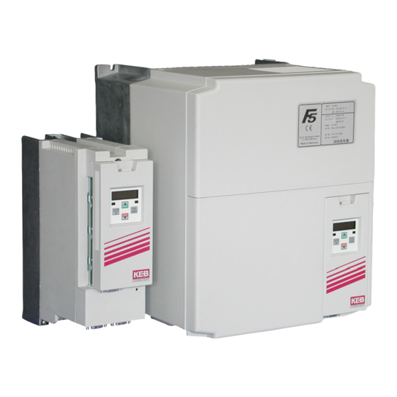
General 1. General 1.1 Product description In selecting the COMBIVERT F5 series inverter, you have chosen a frequency inverter with the highest quality and dynamic performance. It is exclusively designed for smooth speed regulation of a three phase motor. The operation of other electrical loads is forbidden and can lead to destruction of the unit. -
Page 5: Safety Precautions
1.2 Safety Precautions AC motor controls and servo drives contain dangerous voltages which can cause death or serious injury. During operation they can have live "ener- Danger to Life gized" un-insulated parts, moving parts, as well as hot surfaces. Care should be taken to ensure correct and safe operation in order to minimize risk to personnel and equipment. -
Page 6: Part Number System
General 1.3 Part number system 10.F5.G1B–3200 Heatsink & PCB coating 0: Standard A: Conformal Coated & Standard 1: Flat rear B: Conformal Coated & Flat Rear 2: Water-cooled C: Conformal Coated & Water-cooled 3: Convection D: Conformal Coated & Convection Feedback interface (if installed) 0: no Interface 5: Resolver a. -
Page 7: Mounting Instructions
General 1.4 Mounting instructions 1.4.1 Classification The COMBIVERT F5 is classified as an "Open Type" inverter with an IP20 rating and must be mounted inside of a control cabinet. 1.4.2 Physical Mounting Install the inverter in a stationary location offering a firm mounting point with low vibration. -
Page 8: Ambient Conditions
6,560 ft (2000 m) The relative humidity should be limited to 95% without condensation. 1.3.5 Cooling systems The KEB COMBIVERT F5 is available with different cooling systems: Standard - Standard design with heat sink and thermostatically controlled two speed fan. -
Page 9: Electrical Connections
General 1.5 Electrical connections 1.5.1 Safety First RISK OF ELECTRIC SHOCK! Always disconnect supply voltage before servicing the COMBIVERT F5. After disconnecting the supply voltage, always wait 5 minutes before attempting to change the wiring. The internal DC BUS capacitors must discharge. 1.5.2 Voltage Supply The F5 series inverters are suitable for use on a circuit capable of delivering not more than 10kA rms symmetrical amperes, at the inverter's rated maximum voltage. -
Page 10: Fusing
General 1.5.4 Fusing A circuit breaker or a disconnect switch with fuses must be provided as branch circuit protection in accordance with the National Electric Code (NEC) and all local codes. The F5 is to be connected to the supply voltage using Class J fuses (BUSSMANN type LPJ or equivalent) or using a magnetic trip circuit breaker with type D characteristic. -
Page 11: Motor Thermal Protection
General 1.5.6 Motor Thermal Protection The F5 series inverters by default provide motor overload protection at 130% of the inverter's UL rated current. The F5 series inverters are classified as a UL approved solid state overload protection device. It is necessary to activate the function in the software of the inverter. The function meets the requirements set forth in VDE 0660 Part 104, UL508C section 42, and NEC 430 part C. -
Page 12: Dc Supply Connections
General 1.5.8 DC Supply Connections When connecting the F4 series inverter from a DC supply or when connecting several F4 series inverters to a common DC bus the following points should be observed. Each inverter must be fused on both the + and - conductors. BUSSMANN DC fuse type FWP are recommended. -
Page 13: 10High Frequency Shielding
General 1.5.10 High Frequency Shielding Use of shielded cable is recommended when high frequency emissions or easily disturbed signals are present. Examples are as follows: - motor wires connected to inverters: connect shield to ground at both the inverter and motor, NOTE the shield should never be used as the protective ground conductor required by NEC. -
Page 14: 11Example Shield Connections
General 1.5.11 Example shield connections Use shield clamps to make 360° contact on shield. Digital Signals ground at both ends Analog signals ground at one Unshielded signals Local grounding point within 8 inches of the terminal connection 1.5.12 Example control cabinet layout 1. -
Page 15: Technical Data
Technical Data 2. Technical Data 2.1 Technical Data 230V Class Inverter Size Recommended Motor Power [hp] Housing size Input Ratings Supply voltage 180...260 ±0 (230 V rated voltage) Supply voltage frequency [Hz] 50 / 60 +/- 2 Input phases Rated input current [A] 4,0 4,0 2,8 8,0 8,0 5,6 14 9,5 14 9,5 19 13 19 13 [A] –... - Page 16 Technical Data Technical Data 230V Class Continued Inverter Size Recommended Motor Power [hp] Housing size Input Ratings Supply voltage 180...260 ±0 (230 V rated voltage) Supply voltage frequency [Hz] 50 / 60 +/- 2 Input phases Rated input current Recommended maximum input fuse [awg] Recommended wire gauge Output Ratings...
-
Page 17: Technical Data 460V Class
Technical Data 2.2 Technical Data 460V Class Inverter Size Recommended Motor Power [hp] 1/2 Housing size B B D B D B D E G D E Input Ratings Supply voltage 305...500 ±0 (460 V Nominal voltage Supply voltage frequency [Hz] 50 / 60 +/- 2 Input phases... - Page 18 Technical Data Technical Data 460V Class continued Inverter Size Recommended Motor Power [hp] Housing size Input Ratings Supply voltage 305...500 ±0 (460 V Nominal voltage ) Supply voltage frequency [Hz] 50 / 60 +/- 2 Input phases Rated input current Recommended maximum input fuse [awg] Recommended wire gauge...
- Page 19 Technical Data Technical Data 460V Class continued Inverter Size Recommended Motor Power [hp] 50 Housing size Input Ratings Supply voltage 305...500 ±0 (460 V Nominal voltage ) Supply voltage frequency [Hz] 50 / 60 +/- 2 Input phases Rated input current Recommended maximum input fuse [awg] Recommended wire gauge...
- Page 20 Technical Data Inverter Size Recommended Motor Power [hp] Housing size Input Ratings Supply voltage 305...500 ±0 (460 V Nominal voltage ) Supply voltage frequency [Hz] 50 / 60 +/- 2 Input phases Rated input current Recommended maximum input fuse [kcmil] Recommended wire gauge Output Ratings Rated output power [kVA]...
-
Page 21: Dimensions And Weight
Dimensions and Weight 2.3 Dimensions and Weight Ø F Ø F Housing C (with Operator) Weight (width) (height) (depth) 3.00 7.52 * 5.67 (6.22) 0.197 – 6.89 2.0 lbs 2.4 lbs w/filter 3.54 8.66 * 6.30 (6.85) 0.197 – 8.27 4.4 lbs 3.54 9.84 *... -
Page 22: Survey Of Power Circuit Terminals
2.4 Survey of Power Circuit Terminals Housing size A 1 phase Supply side Motor side U, V, W Motor connection L1, N 1 phase supply connection PA, PB Connection for braking resistor (L2) (connect two hot leads e.g. L1,L2 from T1, T2 Connection for temperature sensor a 208V 3 phase system... - Page 23 Power Circuit Terminals Housing size H Note always verify input voltage with name plate for proper connection 230V or 460V PE ++ PE U T1 T2 L1, L2, L3 3 phase supply voltage T1, T2 Connection for temperature sensor + +, - - DC supply connection U, V, W Motor connection...
-
Page 24: Connection Of Power Circuit
Connection of Power Circuit 2.5 Connection of Power Circuit If the supply voltage is connected to the motor Pay attention to the supply voltage 230/460V terminals, the unit will be destroyed! and the correct polarity of the motor! 1-phase connection Use type LPJ fuses for branch circuit N/L2... - Page 25 Connection of Power Circuit On F5 B/G units it is necessary to activate the function through External motor temperature sensor parameter CP.28. (for all units) Don't install temperature sensor wires with other control wires. Must use double shield when running Temperature sensor (PTC ) F5-M/S: temperature sensor wires with motor...
-
Page 26: Accessories
Accessories 3. Accessories The COMBIVERT F5 inverter can be equipped with an external braking 3.1 Braking Resistor resistor for limited 4 quadrant operation. The energy the motor regens into the inverter during deceleration is dissipated through the internal braking transistor to the braking resistor. The braking resistor heats up during braking. - Page 27 Accessories Braking time The braking time is adjusted in the frequency inverter through the deceleration parameters. If the selected deceleration time is too short, either the peak inverter current level or the maximum DC bus voltage will be exceeded. The error message E.OC or E.OP will result. The following formulas can be used to determine an allowable braking time.
-
Page 28: Panel Mount Brake Resistors
Accessories 3.1.2 Panel Mount Brake Resistors Technical data braking resistor Part number COMBIVERT Nominal power Rated [OHM] [kW] 25 s 40 s 230 V - Class 07.BR.100-1180 05, 07 09.BR.100-1100 07, 09 1500 10.BR.100-1683 07, 09, 10, 13(E) 2200 12.BR.100-1333 10, 13(G) 4400 1300... - Page 29 Accessories Part number 07.BR.100-xxxx 0.95 1.57 5.67 0.20 39.0 09.BR.100-xxxx 0.95 1.57 8.74 0.20 39.0 10.BR.100-xxxx 0.95 11.8 1.57 11.22 0.20 39.0 12.BR.100-xxxx 11.8 3.15 11.22 0.20 39.0 13.BR.100-xxxx 15.75 3.15 15.16 0.20 39.0 14.BR.100-xxxx 15.75 3.15 15.16 0.20 39.0 15.BR.110-xxxx 2.48 14.6...
-
Page 30: Parallel Connection Of Braking Resistors
Accessories 3.1.3 Parallel Connection of ϑ=240°C Braking Resistors Terminal strip braking resistor OH2 OHC PA1 PA PA2 PB1 PB PB2 PE PE PE PA1 PA PA2 PB1 PB PB2 PE PE PE OH1 OH2 OHC R2...Rn-1 PA1 PA PA2 PB1 PB PB2 PE PE PE OH1 OH2 OHC PA1 PA PA2... -
Page 31: Back Mount Braking Resistor
Accessories 3.1.4 Back Mount Braking Resistor The inverter mounted braking resistor is designed with space savings in mind. The resistor is mounted directly under the heatsink of the inverter. The heat generated flows vertically out the top of the unit. It should be used only in applications where the braking time is kept to a minimum. - Page 32 Accessories 2 x 20 awg to the terminals T1/T2 (white) 2 x 16 awg to the terminals ++ / PB (red) Frequency Inverter Braking resistor filter 16 awg (red) Housing -> [in] Dimensions 11.4 Back mount braking resis- [in] tors [in] 10.8 [in]...
-
Page 33: Input Filters
Supply fuse Disconnect switch or contactor Line choke Interference suppression filter KEB COMBIVERT F5 Sub panel in control cabinet Line Chokes - Additional Information Interference and or voltage spikes on the supply voltage are created when large loads such as heaters, motors, arc-welders etc. are turned on and off. In some... - Page 34 Accessories Line choke dimensional drawing 230V-Class For Phases I Part number Imp. Dimensions [inches] Wire Weight loss [lb] U0.90.290-0401 14.5 U0.90.290-0402 2.75 1.98 1.44 0.31 x 0.56 22-14 U0.90.290-0801 19.5 U0.90.290-0802 4.75 0.31 x 0.62 22-14 U0.90.290-1201 U0.90.290.1202 3.25 0.31 x 0.62 22-5 U0.90.290-1801 3.25...
- Page 35 Accessories 460V-Class Phases Imp. Part number Dimensions Wire Weight loss [awg] [lb] U0.90.290-0201 U0.90.290-0202 11.3 2.75 4.1 1.98 1.44 0.31 x 0.56 22..14 U0.90.290-0402 4.75 1.98 U0.90.290-0403 3.12 2.35 1.44 0.31 x 0.56 22..14 U0.90.290-0402 4.75 1.98 U0.90.290-0403 3.12 2.35 1.44 0.31 x 0.56 22..14...
-
Page 36: Emi (Ce) - Filter
Accessories 3.2.2 EMI (CE) - Filter The KEBCO COMBIVERT frequency inverters are optionally available with EMI filters. Depending on the housing size they are available from the factory already mounted to the inverter or as filter kits for installation by the user. These filters allow the KEBCO COMBIVERT to meet the CE EMC directive 89/ 339. - Page 37 Accessories Fig. 1 Fig. 2 Rated current LINE INVERTER Voltage V max. Fig. A Weight Shielded [lbs] KEB Art.No.: [V] [A] Terminal Strip Cable 07.E5.T60-0061 2x 4mm² 2x AWG 14 10.E5.T60-0001 1x250 22 2x AWG 10 10.E5.T60-0002 2x AWG 10 4.33...
- Page 38 Accessories Rated Current LINE INVERTER Maximum Voltage KEB Art.Nr.: [lbs] [A] [W] [mm] [mm] 20.E4.T60-1001 110 58 3x25 15.8 10.6 15.7 1.57 0.47 15.2 7.87 0.26 15.7 M8 3x 50 22.E4.T60-1001 500 130 90 3x35 17.4 Dimensions in inches unless specified otherwise...
-
Page 39: Output Filters
EMI on the line. As a result, with longer shielding cables the inverter and KEB EMI filter may no longer comply with the EN norm regarding conducted interference. Thus it is necessary to use a motor choke to reduce these levels. - Page 40 Accessories Motor choke dimensional drawing 230V-Class For Phases I Part number Imp. Dimensions [inches] Wire Weight loss [lb] U0.90.290-0401 14.5 U0.90.290-0402 2.75 1.98 1.44 0.31 x 0.56 22-14 U0.90.290-0801 19.5 U0.90.290-0802 4.75 0.31 x 0.62 22-14 U0.90.290-1201 U0.90.290.1202 3.25 0.31 x 0.62 22-5 U0.90.290-1801 3.25...
- Page 41 Accessories 460V-Class Phases Imp. Part number Dimensions Wire Weight loss [awg] [lb] U0.90.290-0201 U0.90.290-0202 11.3 2.75 4.1 1.98 1.44 0.31 x 0.56 22..14 U0.90.290-0402 4.75 1.98 U0.90.290-0403 3.12 2.35 1.44 0.31 x 0.56 22..14 U0.90.290-0402 4.75 1.98 U0.90.290-0403 3.12 2.35 1.44 0.31 x 0.56 22..14...
-
Page 42: Pwm To Sine Filter
Accessories 3.3.2 PWM to Sine Filter When controlling the motor with pulse width modulation (PWM), the motor can be subject to very rapid voltage rise times, dv/dt of 5…10kV/ uSec. This rapid turn on can create many side effects with long cable runs greater than 150 feet, the primary problem being voltage peaks either at the motor or at the inverter. -
Page 43: Annex
Annex 4. Annex 4.1 Overload Characteristic Curve 1 Curve 2 Time [s] Time [s] Load [%] Load [%] 105 110 115 120 125 130 135 140 145 150 105 110 115 120 125 130 135 140 145 150 160 170 180 190 200 210 220 The characteristic declines device-dependently in this range (see rating plate) On exceeding a load of 105% the overload timer starts. - Page 44 NOTES...
- Page 45 NOTES...
- Page 46 NOTES...
- Page 47 Special Notice to Customer Prior to delivery all products pass several quality and performance inspections in order to guarantee the product is free from defects in manufacturing. When used in accordance with the operating instructions, failure of the unit is not likely. However, if you have reason for concern please contact KEBCO at 651-454-6162 and ask for "inverter technical support".
- Page 48 Telefon 00 49 / 52 63 / 4 01 - 0 • Fax 00 49 / 52 63 / 4 01 - 1 16 Internet: www.keb.de • E-mail: info@keb.de KEB Antriebstechnik GmbH & Co. KG Wildbacher Str. 5 • D - 08289 Schneeberg Telefon 0049 / 37 72 / 67 - 0 •...
Need help?
Do you have a question about the Combivert F5 series and is the answer not in the manual?
Questions and answers