Table of Contents
Advertisement
C O M B I V E R T
D
BETRIEBSANLEITUNG
GB
INSTRUCTION MANUAL
F
MANUEL D'INSTRUCTIONS
I
MANUALE D'ISTRUZIONE
E
MANUAL DE INSTRUCCIONES
Erst Betriebsanleitung Teil 1 lesen !
Read Instruction manual part 1 first !
STOP
Lisez d'abord le manuel d'instructions partie 1 !
Prima leggere le manuale di istruzione 1 parte !
Leer manual de instrucciones parte 1 antes !
0,37...0,75 kW
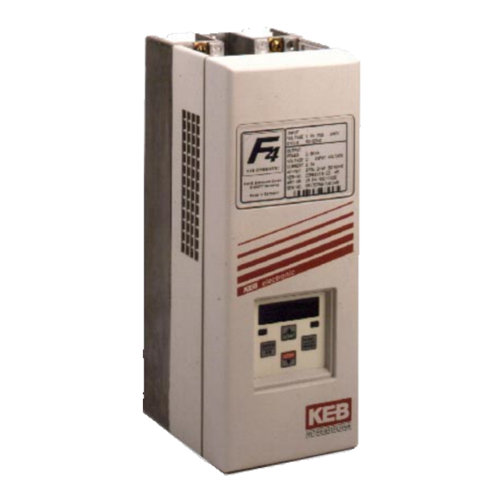
KEB COMBIVERT F4-S
ANTRIEBSTECHNIK
10/98
Advertisement
Table of Contents

Related Manuals for KEB COMBIVERT F4-S Series


Summary of Contents for KEB COMBIVERT F4-S Series
- Page 1 C O M B I V E R T 0,37...0,75 kW BETRIEBSANLEITUNG KEB COMBIVERT F4-S INSTRUCTION MANUAL MANUEL D'INSTRUCTIONS MANUALE D'ISTRUZIONE MANUAL DE INSTRUCCIONES Erst Betriebsanleitung Teil 1 lesen ! Read Instruction manual part 1 first ! STOP Lisez d'abord le manuel d'instructions partie 1 !
- Page 2 Los pictogramas utilizados en Pagina 91 ..112 este manual tienen los significados siguientes: Peligro Información Atención Advertencia Ayuda de obligado Precaución Nota cumplimiento © KEB 00.F4.S0B-K111 10/98...
-
Page 3: Table Of Contents
Table of Contents ANTRIEBSTECHNIK General ............26 Product Description ..........26 Identifikation of the unit ......... 27 Power Circuit ..........27 Performance Data ........... 27 Dimensions ............. 26 Installation Instructions ......... 26 Terminals ..............29 Connection of the Power Circuit ......29 Control circuit ........... -
Page 4: General
General In selecting the KEB COMBIVERT you have chosen a frequency inverter 1. General with the highest demands on quality and dynamic. 1.1 Product Description It exclusively serves for a stepless speed regulation of the three-phase motor. The operation of other electrical utilization equipment is forbidden and can lead to the destruction of the unit. -
Page 5: Identifikation Of The Unit
Mains voltage 180...264 ± 0 % special-purpose Network phase medium frequency motors Mains frequency [Hz] 50 / 60 ± 2 please contact KEB. Output voltage 3 x 0 ... U Mains Output frequency [Hz] 0...409,58 Max. permissible mains fuse [A] Supply cross section Permissible temp. -
Page 6: Dimensions
Power Circuit 2.2 Dimensions Ø F C / C1 Size Weight [kG] 220 240 B1/C1/H1 with submounted filter with screening plate with submounted filter and screening plate 2.4 Installation Direction of the cooling fins minimum clearance in mm Instructions Installation height max. 2000 m. -
Page 7: Terminals
Interference suppression filter (GEN.No. Size 05: 05.U4.00C-B600 / 07: 07.U4.00C-B600) KEB COMBIVERT F4-S Motor choke (Part.No. Size 05: 00.90.290-4245 / Size 07: 00.90.291-2845) !!! Only use up to 4 KHz switching and 51 Hz output frequency !!! For other switching or output frequencies ask KEB. Motor Mounting plate... -
Page 8: Control Circuit
Installation and Connection Control circuit 1 2 3 4 5 6 7 8 9 10 11 12 13 14 3.1 Assignment of Terminal Strip X1 Function Name Description X1.1 NO contact Relay output (30V DC / 1A) X1.2 NC contact Function see parameter CP.22 X1.3 Main contact... -
Page 9: Outputs
– Receiver signal/RS232 RxD-A Receiver signal A/RS485 RxD-B Receiver signal B/RS485 – Voltage supply-Plus +5V (I = 10 mA)) C/C' DGND Data reference potential TxD-A Transmitter signal A/RS485 TxD-B Transmitter signal B/RS485 Informations about other versions of operators contact KEB! -
Page 10: Keyboard
Operation of the Unit 4.1.2 Keyboard When switching on KEB COMBIVERT the value of parameter CP.1 appears. (See Drive mode to switch the keyboard function) The function key (FUNC) FUNC. changes between the parameter value and SPEED parameter number. With UP ( ) and DOWN... -
Page 11: Parameter Summary
Operation of the Unit ANTRIEBSTECHNIK 4.2 Parameter Summary Display Parameter Adjust. range Resolution Factory setting CP. 0 Password input 0...9999 CP. 1 Actual frequency display - 0,1 Hz CP. 2 Inverter status display CP. 3 Actual load CP. 4 Peak load CP. -
Page 12: Operating Display
Operation of the Unit 4.4 Operating Display The 4 parameters below serve to control the frequency inverter during operation. Actual frequency display Display of the actual output frequency with a resolution of 0.0125 Hz. The rotation of the inverter is indicated by the sign. Output frequency 18.3 Hz, rotation forward Examples: Output frequency 18.3 Hz, rotation reverse... -
Page 13: Basic Adjustment Of The Drive
Operation of the Unit ANTRIEBSTECHNIK 4.5 Basic Adjustment The following parameters determine the fundamental operating data of of the Drive the drive. They should be checked and/or adapted to the application. With the adjusted frequency here the inverter reaches a maximal output Rated frequency voltage. - Page 14 Operation of the Unit Deceleration time The parameter determines the time needed in order to decelerate from 100 to 0 Hz. The actual deceleration time is proportional to the frequency change. CP. 8 x delta f actual acceleration time = 100 Hz Adjustment range: 0.01...300 s...
-
Page 15: Special Adjustments
Operation of the Unit ANTRIEBSTECHNIK 4.6 Special The following parameters serve to optimize the drive and adaption onto Adjustments certain applications. These adjustments can be ignored at the initial startup. This function protects the frequency inverter against switching off by Max. - Page 16 Operation of the Unit Speed search When connecting the frequency inverter onto a decelerating motor, an error can be triggered by the differing rotating field frequencies. At activated speed search the inverter searches the actual motor speed, adapts its output frequency and accelerates with the adjusted ramp onto the given set value.
- Page 17 Operation of the Unit ANTRIEBSTECHNIK Slip compensation Slip compensation balances the speed changes caused by the load variation. In order to activate the function, set the value at 1.00 and optimize as directed in the examples below. Adjustment range: -2.50...2.50 Resolution: 0.01 Factory setting:...
- Page 18 Operation of the Unit DC-braking With DC-braking the motor is not decelerated by the ramp. Quick braking is caused by DC voltage, which is applied onto the motor winding. This parameter determines how the DC-braking is triggered. Value Activation DC-braking deactivated DC-braking at switch off of the direction of rotation and in reaching 0Hz.
- Page 19 Operation of the Unit ANTRIEBSTECHNIK Relay output Relay output (terminal X1.1...X1.3) is adjusted in the factory as a fault relay. This parameter can adjust the function of the output onto any function listed in the table below. Value Function No function Generally on Fault relay No function...
-
Page 20: The Drive Mode
Drive mode 4.7 The Drive Mode The drive mode is a operating mode of KEB COMBIVERT to start the drive manually by the operator. After switching the control release the set value and rotation presetting is done exclusively by the keyboard. In order to activate the drive mode the corresponding password in CP.0 must be... -
Page 21: Error Diagnosis
Error messages are represented with an "E. " and the corresponding 5. Error Diagnosis error in the display of the KEB COMBIVERT. The displays and their causes are described below. Occurs, when the intermediate ciruict voltage falls below the permissible value. -
Page 22: Index
Indice LED 31 Index load variation 39 Acceleration time 33, 35, 45 Max. constant current 33, 37, 45 Actual frequency display 33, 34, 45 Max. ramp current 33, 37, 45 Actual load 33, 34, 45 Maximal frequency 33, 36, 45 Analog inputs 30 Minimal frequency 33, 36, 45 Analog output 30... - Page 23 Quick referenz ANTRIEBSTECHNIK Display Parameter Adjust. range Resolution Customer setting CP. 0 Password input 0...9999 CP. 1 Actual frequency display - 0,1 Hz CP. 2 Inverter status display CP. 3 Actual load CP. 4 Peak load CP. 5 Rated frequency 0...409.58 Hz 0.0125 Hz ____________...
-
Page 25: Password
ANTRIEBSTECHNIK Password ENTER Password a) CP-Parameter "read only" FUNC ENTER Password b) CP-Parameter "read/write" FUNC ENTER Password c) Drive mode activ FUNC ✂... - Page 27 Angebote enthalten nur Richtwerte. Technische Änderungen jeder Art behalten wir uns vor. Alle Rechte vorbehalten. Nachdruck, Vervielfältigung und fotomechanische Wiedergabe sind ohne schriftliche Genehmigung durch KEB auch auszugsweise verboten. Prior to delivery all products pass several quality and performance inspections so that malfunctions can be ruled out.
- Page 29 ANTRIEBSTECHNIK...
- Page 30 Telefon 00 49 / 52 63 / 4 01 - 0 • Fax 00 49 / 52 63 / 4 01 - 1 16 Internet: www.keb.de • E-mail: info@keb.de KEB Antriebstechnik GmbH & Co. KG Wildbacher Str. 5 • D - 08289 Schneeberg Telefon 0049 / 37 72 / 67 - 0 •...
Need help?
Do you have a question about the COMBIVERT F4-S Series and is the answer not in the manual?
Questions and answers