KEB COMBIVERT G6 Instructions For Use Manual
Hide thumbs
Also See for COMBIVERT G6:
- Programming manual (326 pages) ,
- Instructions for use and installation (52 pages) ,
- Manual (33 pages)

Subscribe to Our Youtube Channel
Related Manuals for KEB COMBIVERT G6


Summary of Contents for KEB COMBIVERT G6
- Page 1 COMBIVERT G6 INSTRUCTIONS FOR USE | INSTALLATION G6 HOUSING C Translation of the original manual Document 20086993 EN 08...
-
Page 3: Preface
The hardware and software described in this document are products of KEB. The infor- mation contained in this document is valid at the time of publishing. KEB reserves the right to update this document in response to misprints, mistakes or technical changes. -
Page 4: Laws And Guidelines
The customer may use the instructions for use as well as further documents or parts from it for internal purposes. Copyrights are with KEB and remain valid in its entirety. This KEB product or parts thereof may contain third-party software, including free and/ or open source software. -
Page 5: Table Of Contents
TAbLe Of CONTeNTS Table of Contents Preface ..............................3 Signal words and symbols ......................3 More symbols ..........................3 Laws and guidelines ........................4 Warranty and liability ........................4 Support ............................4 Copyright ............................4 Table of Contents ........................... 5 List of figures ............................8 List of Tables ............................ - Page 6 3.3.3 Control cabinet installation ....................33 3.3.3.1 Ventilation in the control cabinet ..................33 4 Installation and Connection ........34 4.1 Overview of the COMbIVerT G6 ....................34 4.2 Connection of the power unit ....................... 35 4.2.1 Connection of the voltage supply ..................35 4.2.1.1 Wiring instructions ......................
- Page 7 TAbLe Of CONTeNTS 5 Certification ..............45 5.1 Ce-Marking ............................. 45 5.2 functional safety ........................... 45 5.3 UL Marking ............................. 45 5.4 further information and documentation ..................48 6 Accessories ..............49 6.1 Mounting kit shield connection braket ..................49 6.2 ferrit rings ............................
-
Page 8: List Of Figures
Figure 5: Mounting distances ......................33 Figure 6: Control cabinet ventilation....................33 Figure 7: Overview of the COMBIVERT G6 ..................34 Figure 8: Input circuit / drive controller type ..................35 Figure 9: Line terminal strip X1A ..................... 36 Figure 10: Connection of the mains supply .................. -
Page 9: List Of Tables
LIST Of TAbLeS List of Tables Table 1: Part code..........................23 Table 2: Climatic environmental conditions ................... 25 Table 3: Mechanical environmental conditions ................26 Table 4: Chemical / mechanical active substances ............... 26 Table 5: Device classification......................27 Table 6: Electromagnetic compatibility ..................27 Table 7: Technical data 400V devices ................... -
Page 10: Glossary
(DIN 5008) IP xx Degree of protection (xx for level) Fieldbus system KEB product The KEB product is subject of this Cyclic duration factor manual Complete drive module including Silicium temperature sensor (pola- auxiliary equipment (control cabinet) - Page 11 GLOSSAry Term used in the safety technology (EN 61508-1...7) for the size of error probability per hour Programmable logic controller PT100 Temperature sensor with R0=100Ω PT1000 Temperature sensor with R0=1000Ω PTC-resistor for temperature detec- tion Pulse width modulation RJ45 Modular connector with 8 lines Synchronous sensorless closed loop SELV Safety Extra Low Voltage (<...
-
Page 12: Standards For Drive Converters / Control Cabinets
STANDArDS fOr DrIVe CONVerTerS / CONTrOL CAbINeTS Standards for drive converters / control cabinets Product standards that apply directly to the drive converter EN 61800-2 Adjustable speed electrical power drive systems - Part 2: General requirements - Rating specifications for low voltage adjustable frequency a.c. power drive systems (VDE 0160-102, IEC 61800-2) EN 61800-3 Speed-adjustable electrical drives. Part 3: EMC requirements and specific test methods (VDE 0160-103, IEC 61800-3) -
Page 13: Standards That Are Used In The Environment Of The Drive Converter
STANDArDS fOr DrIVe CONVerTerS / CONTrOL CAbINeTS EN 61000-4-5 Electromagnetic compatibility (EMC) - Part 4-5: Testing and measurement techniques - Surge immunity test (IEC 61000-4-5); German version EN 61000-4-5 EN 61000-4-6 Electromagnetic compatibility (EMC) - Part 4-6: Testing and measurement techniques - Immunity to conducted disturbances, induced by radio-frequency fields (IEC 61000-4-6); German version EN 61000-4-6 EN 61000-4-34... -
Page 14: Basic Safety Instructions
► Read the instructions for use ! ► Observe the safety and warning instructions ! ► If anything is unclear, please contact KEB Automation KG ! 1.1 Target group This instruction manual is determined exclusively for electrical personnel. Electrical per- sonnel for the purpose of this instruction manual must have the following qualifications: •... -
Page 15: Installation
bASIC SAfeTy INSTrUCTIONS Drive converters contain electrostatic sensitive components. ► Avoid contact. ► Wear ESD-protective clothing. Do not store drive converters • in the environment of aggressive and/or conductive liquids or gases. • with direct sunlight. • outside the specified environmental conditions. 1.3 Installation DANGer Do not operate in an explosive environment! -
Page 16: Electrical Connection
If personnel protection is required during installation of the system, suitable protective devices must be used for drive converters. www.keb.de/fileadmin/media/Manuals/knowledge/04_techinfo/00_gene- ral/ti_rcd_0400_0002_gbr.pdf Installations which include drive converter shall be equipped with additional control and protective devices in accordance with the relevant applicable safety requirements, e.g. -
Page 17: Emc-Compatible Installation
According to it is permissible to disconnect already tested com- EN 60204-1 ponents. Drive converters of the KEB Automation KG are delivered ex works voltage tested to 100% according to product standard. 1.4.3 Insulation measurement An insulation measurement (in accordance with chapter 18.3) with DC... -
Page 18: Start-Up And Operation
If a drive converter with electrolytic capacitors in a DC link (see technical data) has not been in operation for more than one year, observe the following instructions. www.keb.de/fileadmin/media/Manuals/knowledge/04_techinfo/00_gene- ral/ti_format_capacitors_0400_0001_gbr.pdf NOTICE Continuous operation (S1) with load > 60 % ! Premature ageing of the electrolytic capacitors ! ►... -
Page 19: Maintenance
(mains on) (e.g. due to large rotating masses). Switching an the input For applications that require cyclic switching off and on of the drive converter, maintain an off-time of at least 5 min after the last switch on. If you require shorter cycle times please contact KEB Automation KG. Short-circuit resistance The drive converters are conditional short-circuit proof. After resetting the internal pro- tection devices, the function as directed is guaranteed. -
Page 20: Repair
1.8 Disposal Electronic devices of the KEB Automation KG are exclusively professional devices for further industrial processing (so-called B2B devices). Manufacturers of B2B devices are obliged to take back and recycle devices manufac- tured after 14.08.2018. -
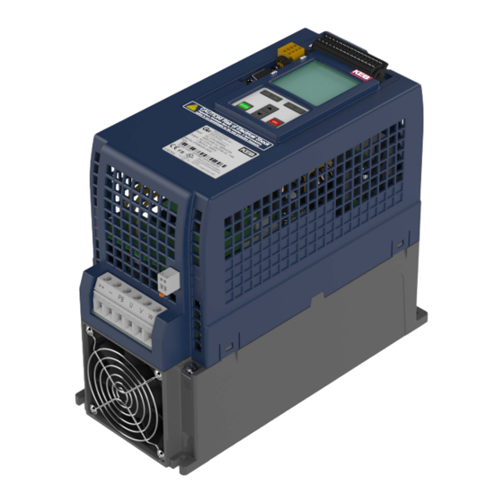
Page 21: Product Description
PrODUCT DeSCrIPTION 2 Product Description The device series COMBIVERT G6 concerns to drive controllers, which are developed for the universal operation at open-loop three-phase drives. The COMBIVERT is opti- mized for the operation at synchronous and asynchronous motors and is equipped with an integrated EMC filter. -
Page 22: Product Features
Series: COMBIVERT G6 Power range: 5.5...11 kW / 400 V Housing: The COMBIVERT G6 is characterized by the following features: • Operation of three-phase asynchronous motors and three-phase synchronous motors, in operating modes open-loop or closed-loop without speed feedback •... -
Page 23: Part Code
D: Like 3 with STO f=0 Hz C: Analog / digital (standard) D: CAN ® 2) Control type E: IO-Link ® 3) F: EtherCAT ® 1) I: VARAN Series COMBIVERT G6 Inverter size 07…19 Table 1: Part code continued on the next page... - Page 24 PrODUCT DeSCrIPTION EtherCAT is registered trademark and patented technology, licensed ® by Beckhoff Automation GmbH, Germany CANopen is registered trademark of CAN in AUTOMATION - Interna- ® tional Users and Manufacturers Group e.V. IO-LINK is registered trademark of PROFIBUS user organisation e.V. ®...
-
Page 25: Technical Data
3 Technical Data Unless otherwise indicated, all electrical data in the following chapter refer to a 3-phase AC voltage supply. 3.1 Operating conditions 3.1.1 Climatic environmental conditions Storage Standard Class Notes Ambient temperature -25…55 °C EN 60721-3-1 Relative humidity EN 60721-3-1 5…95 % (without condensation) Storage height –... -
Page 26: Mechanical Environmental Conditions
3.1.2 Mechanical environmental conditions Storage Standard Class Notes Vibration amplitude 1.5 mm (2…9 Hz) Vibration limits EN 60721-3-1 Acceleration amplitude 5 m/s² (9…200 Hz) Shock limit values 40 m/s²; 22 ms EN 60721-3-1 Transport Standard Class Notes Vibration amplitude 3.5 mm (2…9 Hz) Vibration limits Acceleration amplitude 10 m/s²... -
Page 27: Electrical Operating Conditions
3.1.4 electrical operating conditions 3.1.4.1 Device classification requirement Standard Class Notes – EN 61800-5-1 Overvoltage category EN 60664-1 – Non-conductive pollution, occasional conden- Pollution degree EN 60664-1 sation when PDS is out of service Table 5: Device classification 3.1.4.2 Electromagnetic compatibility For devices without an internal filter, an external filter is required to comply with the fol- lowing limit values. -
Page 28: Technical Data 400V Devices
TeCHNICAL DATA 400V DeVICeS 3.2 Technical data 400V devices Device size Housing Mains phases Rated apparent output power / kVA Max. rated motor power / kW Rated output current 16.5 Rated output current UL N_UL Max. short time current Overcurrent Maximum current 0Hz/corner frequency f at f = 4 kHz... -
Page 29: Overload And Derating
The technical data are for 2/4-pole standard motors. With other pole numbers the drive controller must be dimensioned onto the rated motor current. Contact KEB for special or medium frequency motors. The service life of the drive controller with voltage DC link depends on the current load of the electrolytic capacitors in the DC link. -
Page 30: Figure 2: Overload Characteristic
TeCHNICAL DATA 400V DeVICeS t / s 105 110 115 120 125 130 135 140 145 150 160 170 180 190 200 210 220 Figure 2: Overload characteristic On exceeding a load of 105% the overload integrator starts. When falling below the integrator counts backwards. -
Page 31: Dimensions And Weights
DIMeNSIONS AND WeIGHTS 3.3 Dimensions and weights 3.3.1 built-in version Housing Weight 4.6 kg Dimensions All dimensions in mm Figure 3: Built-in version with optional mounting kit... -
Page 32: Flat Rear Version
3.3.2 flat rear version Housing Weight 3.9 kg Dimensions All dimensions in mm Figure 4: Flat rear version with optional mounting kit Heat-conducting paste For information on the correct application of the heat-conducting paste visit under the search term www.keb.de "Heat-conducting paste“. -
Page 33: Control Cabinet Installation
DIMeNSIONS AND WeIGHTS 3.3.3 Control cabinet installation The power dissipation for the control cabinet dimension is to be taken from the technical data. => „3.2 Technical data 400V devices“. Mounting distances Dimension Distance in mm Distance in inch Distance to preceding elements in the control cab- inet door. -
Page 34: Installation And Connection
OVerVIeW Of THe COMbIVerT G6 4 Installation and Connection 4.1 Overview of the COMbIVerT G6 Housing C Name Description Terminal block for three-phase motor , braking resistor and DC supply Diagnostic interface RS232/485 interface with DIN66019-II Safety function STO (optional) -
Page 35: Connection Of The Power Unit
4.2 Connection of the power unit 4.2.1 Connection of the voltage supply The COMBIVERT G6-C corresponds to the drive controller type A1. This type can be supplied both by mains and via DC terminals. The starting current limiting is arranged before the DC link. -
Page 36: Line Terminal Strip X1A
CONNeCTION Of THe POWer UNIT 4.2.1.2 Line terminal strip X1A Name function Cross-section Tightening torque AWG without mm² with wire-end wire-end Mains con- 1.2…1.5 Nm ferrule ferrule nection L1, L2, L3 12 lb-inch 20...8 2,5...10 3-phase stranded wire Connection 1.3 Nm Screw M4 protective for ring crimp connector... -
Page 37: Ac Connection
Mains fuses Type gG or MCCB Mains contactor Mains choke 13, 14 or 15Z1B04-1000 KEB COMBIVERT G6-C Figure 10: Connection of the mains supply 4.2.3.2 Supply cable The conductor cross-section of the supply cable is dependent on the input current, the cable according to manufacturer's data, as well as the VDE regulations. -
Page 38: Terminal Block X1B Dc Connection
Motor cable / m Motor cable / m Motor cable / m Motor cable / m Size Voltage / V (standard) (low-capacitance) (standard) (low-capacitance) Table 9: Cable-fed disturbances depending on the motor cable length at AC supply The cable length can be significantly extended by using motor chokes or filters. KEB recommends the use of motor chokes or filters for a line length upto 50 m. Motor chokes or filters are absolutely necessary upto 100 m. -
Page 39: Motor Cable Length At Operation With Dc Voltage
CONNeCTION Of THe POWer UNIT 4.2.5.3 Motor cable length at operation with DC voltage The maximum motor cable length at DC operation is basically dependent on the capaci- ty of the motor cable. The internal filter is not active at DC operation. External measures must be taken here, if necessary. The following data apply for operation under rated conditions. -
Page 40: Terminal Block X1B Motor Connection
Terminal block X1B motor connection 4.2.5.8 Wiring of the motor ➃ T1 T2 ➄ Legend 1 KEB COMBIVERT Apply motor cable, shielding on both sides over a large surface on the motor housing 3 Three-phase motor Temperature monitoring (optional) =>... -
Page 41: Connection Of A Braking Resistor
Only intrinsically safe braking resistors permitted ! Only "intrinsically safe" braking resistors are permissible for this oper- ation, since these resistors interrupt themselves at fault such as safety fuse without fire risk. Technical data and design for intrinsically safe braking re- sistors. www.keb.de/fileadmin/media/Manuals/dr/ma_dr_safe-braking-resis- tors-20106652_en.pdf... -
Page 42: Use Of Non-Intrinsically Safe Braking Resistors
► Only use braking resistors with temperature sensor. ► Evaluate temperature sensor. ► Trigger fault on the drive controller (e.g. external input). ► Switch off input voltage (e.g. input contactor). ► Connection examples for non-intrinsically safe braking resistors => Instructions for use „Installation Braking Resistors“. Instructions for use „Installation Braking Resistors“ www.keb.de/fileadmin/media/Manuals/dr/ma_dr_braking-resis- tors-20116737_en.pdf... -
Page 43: Connection Of A Temperature Detection
CONNeCTION Of THe POWer UNIT 4.2.7 Connection of a temperature detection 4.2.7.1 Temperature detection terminals T1, T2 The COMBIVERT G6 is delivered with a PTC evaluation. The function corresponds to and works in accordance with the following table: EN 60947-8... -
Page 44: Use Of The Temperature Detection
CALCULATION Of THe MOTOr VOLTAGe 4.2.7.3 Use of the temperature detection The temperature detection provides the user all possibilities within the resistance range specified in „4.2.7 Connection of a temperature detection“. This can be: Thermal contact (NC contact) e.g. at the brake resistor ①... -
Page 45: Certification
EN 61800-5-2 5.3 UL Marking Acceptance according to UL is marked at KEB drive controllers with the adjacent logo on the nameplate. To be conform according to UL for use on the North American and Canadian Market the following additionally instructions must be observed (original text of the UL-File): “During the UL evaluation, only Risk of Electrical Shock and Risk of Fire aspects were... - Page 46 CerTIfICATION • 480V In/output terminals: „Use 60/75 °C Copper Conductors Only,max Wire Size: 8 AWG, strip wire insulation at 10 mm. • “During the UL evaluation, only Risk of Electrical Shock and Risk of Fire aspects were investigated. Functional Safety aspects were not evaluated” • In order to comply with CSA C22.2 No. 14-2010 (cUL) following external Input Chokes need to be installed: See table 1 below ! Table 1: Mains input chokes for CSA applications: Cat.
- Page 47 CerTIfICATION WARNING – The opening of the branch circuit protective device may be an indication that a fault current has been interrupted. To reduce the risk of fire or electrical shock, current-carrying parts and other components of the controller should be examined and replaced if damaged. If burnout of the current element of an overload relay occurs, the complete overload relay must be replaced.
-
Page 48: Further Information And Documentation
CerTIfICATION 5.4 further information and documentation You find supplementary manuals and instructions for the download under www.keb.de/de/service/downloads General manuals • EMC and safety instructions • Instructions for additional control boards, safety modules, fieldbus modules, etc. Instruction and information for construction and development • Input fuses in accordance with UL • Programming manual for control and power unit •... -
Page 49: Accessories
ACCeSSOrIeS 6 Accessories 6.1 Mounting kit shield connection braket A mounting kit is available for large surface of the shieldings of the connecting cables: Material number Name C0G6T88-0001 Mounting kit shield connection braket Table 12: Mounting kit shield connection braket for G6 housing C Figure 20: G6 housing C with optional mounting kit... -
Page 50: Ferrit Rings
ACCeSSOrIeS 6.2 ferrit rings To comply with the EMC limit values it is absolutely necessary to use the supplied ferrite rings. Use of the supplied ferrite rings. www.keb.de/fileadmin/media/Manuals/dr/ma_dr_g6-zub-inst-ferrite- rings-20176092_en.pdf Figure 21: Use of the ferrite rings in the mounting kit... -
Page 51: Revision History
2014-04 Converted to document number. Revision 1G is identical with version 00 2015-12 Added note on use of ferrite rings 2018-03 Insertion of dimensions; Conversion to new KEB corporate identity optics 2018-10 Editorial changes, warning symbol inserted 2019-05 Dimensions for mounting kit inserted 2019-05 Revised mounting kit added 2020-03 Adjustments type code;... - Page 52 NOTES...
- Page 53 Tel: +33 149620101 Fax: +33 145767495 c / Mitjer, Nave 8 - Pol. Ind. LA MASIA E-Mail: info@keb.fr Internet: www.keb.fr 08798 Sant Cugat Sesgarrigues (Barcelona) Spain Tel: +34 93 8970268 Fax: +34 93 8992035 E-Mail: vb.espana@keb.de Germany Geared Motors KEB Antriebstechnik GmbH...
- Page 54 Automation with Drive www.keb.de KEB Automation KG Suedstrasse 38 32683 Barntrup Tel. +49 5263 401-0 E-Mail: info@keb.de...
Need help?
Do you have a question about the COMBIVERT G6 and is the answer not in the manual?
Questions and answers