Mitsubishi MELSEC L Series User Manual
Hide thumbs
Also See for MELSEC L Series:
- User manual (440 pages) ,
- Programming manual (1296 pages) ,
- Reference manual (532 pages)
Table of Contents
Advertisement
Quick Links
Advertisement
Table of Contents
Troubleshooting

Related Manuals for Mitsubishi MELSEC L Series


Summary of Contents for Mitsubishi MELSEC L Series
-
Page 3: Safety Precautions
SAFETY PRECAUTIONS (Read these precautions before using this product.) Before using this product, please read this manual and the relevant manuals carefully and pay full attention to safety to handle the product correctly. In this manual, the safety precautions are classified into two levels: " WARNING"... - Page 4 [Design Precautions] WARNING (4) When the programmable controller detects an abnormal condition, it stops the operation and all outputs are: • Turned off if the overcurrent or overvoltage protection of the power supply module is activated. • Held or turned off according to the parameter setting if the self-diagnostic function of the CPU module detects an error such as a watchdog timer error.
- Page 5 [Design Precautions] CAUTION ● Do not install the control lines or communication cables together with the main circuit lines or power cables. Keep a distance of 100mm or more between them. Failure to do so may result in malfunction due to noise. ●...
- Page 6 Always ground the FG and LG terminals to the protective ground conductor. Failure to do so may cause malfunction. ● Mitsubishi programmable controllers must be installed in control panels. Connect the main power supply to the power supply module in the control panel through a relay terminal block.
- Page 7 [Startup and Maintenance Precautions] WARNING ● Do not touch any terminal while power is on. Doing so will cause electric shock or malfunction. ● Correctly connect the battery connector. Do not charge, disassemble, heat, short-circuit, solder, or throw the battery into the fire. Also, do not expose it to liquid or strong shock. Doing so will cause the battery to produce heat, explode, ignite, or leak, resulting in injury and fire.
- Page 8 [Disposal Precautions] CAUTION ● When disposing of this product, treat it as industrial waste. When disposing of batteries, separate them from other wastes according to the local regulations. (For details on battery regulations in EU member states, refer to Page 404, Appendix 11.) [Transportation Precautions] CAUTION ●...
-
Page 9: Conditions Of Use For The Product
PRODUCT in one or more of the Prohibited Applications, provided that the usage of the PRODUCT is limited only for the specific applications agreed to by Mitsubishi and provided further that no special quality assurance or fail-safe, redundant or other safety features which exceed the general specifications of the PRODUCTs are required. -
Page 10: Introduction
INTRODUCTION Thank you for purchasing the Mitsubishi MELSEC-L series programmable controllers. This manual describes the specifications of the hardware, such as CPU modules and power supply modules, maintenance and inspection of the system, and troubleshooting. Before using this product, please read this manual and the relevant manuals carefully and develop familiarity with the functions and performance of the MELSEC-L series programmable controller to handle the product correctly. -
Page 11: Relevant Manuals
RELEVANT MANUALS (1) CPU module user's manual Manual name Description <manual number (model code)> MELSEC-L CPU Module User's Manual (Function Explanation, Program Fundamentals) Functions and devices of the CPU module, and programming <SH-080889ENG, 13JZ35> MELSEC-L CPU Module User's Manual (Built-In Ethernet Function) The built-in Ethernet function of the CPU module <SH-080891ENG, 13JZ37>... - Page 12 (4) I/O module and intelligent function module manual Manual name Description <manual number (model code)> MELSEC-L I/O Module User's Manual Specifications and troubleshooting of the I/O module <SH-080888ENG, 13JZ34> System configuration, specifications, procedures before operation, data MELSEC-L Serial Communication Module User's Manual (Basic) communication methods (basic), and troubleshooting of the serial <SH-080894ENG, 13JZ40>...
- Page 13 Memo...
-
Page 14: Table Of Contents
CONTENTS CONTENTS SAFETY PRECAUTIONS ............. 1 CONDITIONS OF USE FOR THE PRODUCT . - Page 15 CHAPTER 7 POWER SUPPLY MODULE Part Names..............Specifications .
- Page 16 15.1.1 When the POWER LED does not turn on ........15.1.2 When the MODE LED does not turn on .
- Page 17 ......383 Appendix 7.1 Measures to comply with the EMC Directive ..... 395 Appendix 7.2 Measures to comply with the Low Voltage Directive Appendix 8 General Safety Requirements .
-
Page 18: Manual Page Organization
MANUAL PAGE ORGANIZATION In this manual, pages are organized and the symbols are used as shown below. The following page illustration is for explanation purpose only, and is different from the actual pages. "" is used for screen names and items. The chapter of the current page is shown. -
Page 19: Terms
TERMS Unless otherwise specified, this manual uses the following terms. Term Description CPU module The abbreviation for the MELSEC-L series CPU module Power supply module The abbreviation for the MELSEC-L series power supply module Branch module The abbreviation for the MELSEC-L series branch module Extension module The abbreviation for the MELSEC-L series extension module END cover... -
Page 20: Packing List
PACKING LIST The following items are included in the package of this product. Before use, check that all the items are included. L02CPU CPU module (L02CPU) + END cover (L6EC) Safety Guidelines (IB(NA)-0800456) (A dummy cover for the display unit is attached.) Battery (Q6BAT) Battery replacement data stickers to fill out (installed in the CPU module) - Page 21 L26CPU-BT CPU module (L26CPU-BT) + END cover (L6EC) Safety Guidelines (IB(NA)-0800456) (A dummy cover for the display unit is attached.) Battery (Q6BAT) Battery replacement data stickers to fill out (installed in the CPU module) (three stickers on one sheet) A set of terminating resistors Terminating resistor 110 1/2W 2 pieces...
- Page 22 L02CPU-P CPU module (L02CPU-P) + END cover (L6EC) Safety Guidelines (IB(NA)-0800456) (A dummy cover for the display unit is attached.) Battery (Q6BAT) Battery replacement data stickers to fill out (installed in the CPU module) (three stickers on one sheet)
- Page 23 L26CPU-PBT CPU module (L26CPU-PBT) + END cover (L6EC) Safety Guidelines (IB(NA)-0800456) (A dummy cover for the display unit is attached.) Battery (Q6BAT) Battery replacement data stickers to fill out (installed in the CPU module) (three stickers on one sheet) A set of terminating resistors Terminating resistor 110 1/2W 2 pieces...
-
Page 24: Chapter 1 Features
CHAPTER 1 FEATURES This chapter describes the features of a MELSEC-L series CPU module. (1) Modules can be interconnected. Using connectors on the both sides of modules, modules can be interconnected. Therefore, expanding a system in a minimum space is possible. (2) The built-in functions allow system cost reduction. - Page 25 CHAPTER 1 FEATURES (3) Use of a display unit improves operation. By attaching a display unit, the following operations can be performed without a personal computer. • Checking and changing device values and checking wiring after device value change • Displaying and setting the time •...
-
Page 26: Chapter 2 System Configuration
CHAPTER 2 SYSTEM CONFIGURATION This chapter describes overall system configuration, precautions for system configuration, and peripheral configuration. Overall System Configuration This section describes overall system configuration using a MELSEC-L series CPU module. Display unit (optional) END cover I/O modules or intelligent function RS-232 adapter Power supply module... -
Page 27: Precautions For Configuring A System
CHAPTER 2 SYSTEM CONFIGURATION Precautions for Configuring a System This section describes precautions for configuring a system. (1) Number of extension blocks and connectable modules The number of extension blocks differs depending on the CPU module used. Accordingly, the maximum configuration in a system differs. - Page 28 Some intelligent function modules and network modules occupy the spaces for two modules. Before configuring a system, check the number of modules occupied by one module in the user's manual for the module used. This is the number of modules that can be set in parameters using a programming tool. By using dedicated instructions, the maximum number of these modules can be connected.
- Page 29 CHAPTER 2 SYSTEM CONFIGURATION (3) Rated output current (5VDC) Configure a system so that the total current consumption may not exceed 5VDC, the rated output current of the power supply module. For the specifications of the power supply module, refer to Page 67, Section 7.2.
-
Page 30: Peripheral Configuration
Peripheral Configuration This section describes peripheral configuration using a MELSEC-L series CPU module. CPU module RS-232 adapter Display unit Ethernet cable SD memory card RS-232 cable Personal computer (GX Works2, GX Developer, GX Configurator) USB cable (Connector type A-mini B) Use an RS-232 cable meeting the specifications. -
Page 31: Chapter 3 System Start-Up Procedure
CHAPTER 3 SYSTEM START-UP PROCEDURE CHAPTER 3 SYSTEM START-UP PROCEDURE This chapter describes a procedure for starting a system. Start Install modules. Check box Page 31, CHAPTER 4 Install a power supply module, a CPU module, I/O modules, intelligent function modules, branch modules, extension modules, an END cover, and a display unit. - Page 32 From previous page Checkbox Write data to the CPU module. Operating manual for the programming tool used Write programs and parameters to the CPU module with a programming tool. Restart the system. Page 64, Section 6.3 Restart the system in either of the following ways: Power off and then on the system.
-
Page 33: Chapter 4 Installation And Wiring
CHAPTER 4 INSTALLATION AND WIRING CHAPTER 4 INSTALLATION AND WIRING This chapter describes the installation and the wiring of modules. Installation Environment and Installation Position When installing the programmable controller in a control panel, fully consider its operability, maintainability, and environmental resistance. -
Page 34: Mounting The Modules
Mounting the Modules This section describes how to interconnect modules and how to mount them on a DIN rail. ● Modules must be mounted on a DIN rail. ● Connect an END cover on the right of the terminal module. 4.2.1 Precautions for connecting and mounting modules •... -
Page 35: Connecting Modules
CHAPTER 4 INSTALLATION AND WIRING 4.2.2 Connecting modules This section describes a procedure for connecting modules with an example of how to connect the L02CPU with the L61P. Shut off the external power supply for the system in all phases before connecting or disconnecting modules. (1) Connecting modules To release the module joint levers located at the top and bottom of the L02CPU:... -
Page 36: Mounting The Modules On A Din Rail
4.2.3 Mounting the modules on a DIN rail This section describes a procedure for mounting the modules on a DIN rail. (1) Mounting procedure Pull down DIN rail hooks on the back of the modules until they click. Hang the upper tabs of the modules on a DIN rail, and push the modules in position. - Page 37 CHAPTER 4 INSTALLATION AND WIRING Hitch the bottom hook of the DIN rail stopper to the bottom of the DIN rail. Hitch the hook according to the orientation of the arrow on the front of the stopper. Hitch the hook to bottom of the DIN rail.
- Page 38 Do not slide modules from the edge of the DIN rail when mounting them. Doing so may damage the metal part located on the back of the module. (2) Removal procedure Remove the modules from the DIN rail in the reverse manner of (1). (3) Applicable DIN rail model (IEC 60715) •...
-
Page 39: Changing Modules On A Din Rail
CHAPTER 4 INSTALLATION AND WIRING 4.2.4 Changing modules on a DIN rail This section describes a procedure for changing modules on a DIN rail by sliding them rightward. Remove the mounted terminal block and disconnect the connectors beforehand. Remove the DIN rail stopper on the right edge. Pull down DIN rail hooks on the back of the modules. - Page 40 Slide the modules and plug the connectors. Lock the module joint levers. Lock the DIN rail hooks and attach the DIN rail stopper. Page 34, Section 4.2.3) Do not slide modules from the edge of the DIN rail when mounting them. Doing so may damage the metal part located on the back of the module.
-
Page 41: Attaching And Removing A Display Unit
CHAPTER 4 INSTALLATION AND WIRING 4.2.5 Attaching and removing a display unit This section describes a procedure for attaching a display unit on the CPU module. Shut off the external power supply for the system in all phases before attaching or removing a display unit. After removing the display unit, always attach a display unit dummy cover for protecting the connector. -
Page 42: Mounting And Removing A Terminal Block
4.2.6 Mounting and removing a terminal block This section describes a procedure for mounting and removing an 18-point terminal block. (1) Removal procedure Open the terminal cover and loosen the terminal block mounting screw. Terminal block mounting screw Press the terminal block fixing holes until the lower part of the terminal block is disengaged from the module, and then remove the terminal block. - Page 43 CHAPTER 4 INSTALLATION AND WIRING (2) Mounting procedure Fully insert the projections on the top of the Terminal block fixing hole terminal block into the terminal block fixing holes and press the terminal block until it snaps into place. Open the terminal cover and tighten the terminal block mounting screw.
-
Page 44: Inserting And Removing An Sd Memory Card
4.2.7 Inserting and removing an SD memory card This section describes a procedure for inserting/removing an SD memory card into/from the CPU module. (1) Insertion procedure Check that the SD memory card lock switch is on the upper position. Insert an SD memory card into the SD memory card slot. - Page 45 CHAPTER 4 INSTALLATION AND WIRING (2) Removal procedure Slide the SD memory card lock switch up. Check that the SD LED turns off before removing the SD memory card while the CPU module is on. Push the SD memory card into the slot once, and then pull the card out.
-
Page 46: Wiring
Wiring This section describes precautions for wiring of power cables and wiring to I/O equipment. (1) Precautions • Do not connect 24VDC outputs from several power supplies in parallel to supply power to one I/O module. Parallel connection will damage the power supplies and/or the I/O module. •... - Page 47 CHAPTER 4 INSTALLATION AND WIRING (2) Precautions The following describes precautions for wiring to power supply modules. • Wire cables of the power supply for the programmable controller, I/O power supply, and motor power supply separately as shown below. Programmable Isolation Main controller power...
- Page 48 • Use an online UPS (uninterruptible power supply) with a power distortion factor of 5% or less or a line interactive UPS. If a standby UPS is used, use a Mitsubishi low-capacity UPS "FREQUPS FW-F series" (hereinafter FW-F series) .
-
Page 49: Wiring To An 18-Point Screw Terminal Block
CHAPTER 4 INSTALLATION AND WIRING 4.3.2 Wiring to an 18-point screw terminal block (1) Precautions • For the 18-point screw terminal block wiring, use a solderless terminal of 0.8mm or less in thickness. Up to two solderless terminals can be connected to one terminal block. •... -
Page 50: Wiring To A Spring Clamp Terminal Block
4.3.3 Wiring to a spring clamp terminal block (1) Precautions • A bar terminal is recommended for the spring clamp terminal block. • Tighten the terminal block mounting screw within the following specified torque range. Screw type Tightening torque range Terminal block mounting screw 0.20 to 0.30N•m •... -
Page 51: Wiring To Connectors
CHAPTER 4 INSTALLATION AND WIRING 4.3.4 Wiring to connectors (1) Precautions • Connectors for external devices (A6CON ) must be crimped, pressed, or correctly soldered. • Plug connectors for external devices (A6CON ) securely to the module and tighten the two screws. •... - Page 52 (2) Applicable connectors The following tables list the crimp tool, pressure-displacement tools, and the types of connectors used for modules. (a) 40-pin connector Type Model Applicable wire size Soldering connector A6CON1 0.3mm (AWG22) (stranded) (straight out type) Crimp connector A6CON2 0.088 to 0.24mm (AWG28 to 24) (stranded) (straight out type)
- Page 53 CHAPTER 4 INSTALLATION AND WIRING (3) Wiring method (a) A6CON1, A6CON4 Loosen the four fixing screws on the connector and remove the screws. Open the connector cover from the connector side. Solder the wires and coat them with heat shrinkable Heat shrinkable tube tubes.
- Page 54 Place the connector on one side of the connector cover and put the fixing screws through the screw holes. Cover the other connector cover onto the connector. Tighten the four screws.
- Page 55 CHAPTER 4 INSTALLATION AND WIRING (b) A6CON2 The following table shows the specifications of the FCN-363T-T005/H used for the A6CON2. Outside Length of Applicable wire Cross-section Crimp height diameter of stripped wire size area of wire coated wire part φ1.2 or less AWG24 1.25 to 1.30 3.0 to 4.0...
- Page 56 (4) Plugging a connector (a) Installation procedure Plug the connector into the slot on the module. Connector screw Tighten the two connector screws (M2.6). (b) Removal procedure Loosen the two connector screws and pull out the connector from the module.
-
Page 57: Connecting Extension Cables
CHAPTER 4 INSTALLATION AND WIRING 4.3.5 Connecting extension cables (1) Precautions • Do not step on an extension cable. • When laying an extension cable, secure 76mm or more as the minimum cable bending radius. • If it is less than 76mm, malfunction may occur due to characteristic deterioration or cable disconnection. •... -
Page 58: Grounding
(3) Specifications Model Item LC06E LC10E LC30E Cable length 0.6m 1.0m 3.0m Conductor resistance value 0.034Ω 0.051Ω 0.14Ω Weight 0.19kg 0.23kg 0.45kg When different models of extension cables are used in combination, select cables so that the overall distance becomes 3.0m or less. -
Page 59: Chapter 5 General Specifications
Do not use or store the programmable controller under pressure higher than the atmospheric pressure of altitude 0m. Doing so may cause malfunction. When using the programmable controller under pressure, please consult your local Mitsubishi Electric representative. This indicates the section of the power supply to which the equipment is assumed to be connected between the public electrical power distribution network and the machinery within premises. - Page 60 Memo...
-
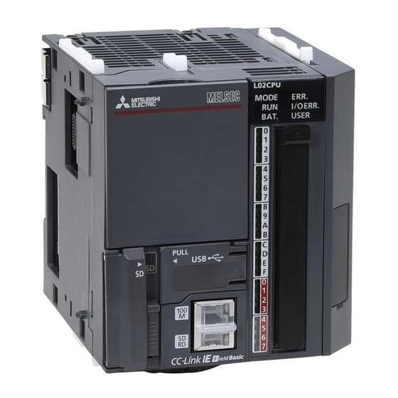
Page 61: Chapter 6 Cpu Module
CHAPTER 6 CPU MODULE CHAPTER 6 CPU MODULE This chapter describes the specifications and hardware operation of a CPU module. Part Names Battery holder (bottom surface) Name Application Indicates the mode of the CPU module. On (green): Normal operation mode Flashing (green): Force mode (when the function is active) MODE LED The forced on/off function for external I/O, the executional conditioned device... - Page 62 Name Application Indicates the status of the annunciator (F). USER LED On (red): The annunciator (F) is on. Off: The module is operating normally or the annunciator (F) is not used. Indicates the data transmission speed over Ethernet. 100M LED On (green): Data is communicated at a speed of 100Mbps.
-
Page 63: Specifications
CHAPTER 6 CPU MODULE Specifications This section describes the specifications of a CPU module. (1) Hardware specifications Item L02CPU, L02CPU-P L26CPU-BT, L26CPU-PBT Control method Stored program repeat operation Refresh mode I/O control mode (Direct mode is available by specifying the direct access input/output (DX, DY).) Function block, relay symbol language, MELSAP3 (SFC), MELSAP-L, structured text (ST), logic Programming language (sequence control language) symbolic language... - Page 64 (2) Device specifications Item L02CPU, L02CPU-P L26CPU-BT, L26CPU-PBT Number of I/O device points (number of points available 8192 points (X/Y0 to X/Y1FFF) on a program) Number of I/O points 1024 points (X/Y0 to X/Y3FF) 4096 points (X/Y0 to X/YFFF) Internal relay (M) 8192 points (M0 to M8191) by default (changeable) Latch relay (L) 8192 points (L0 to L8191) by default (changeable)
- Page 65 CHAPTER 6 CPU MODULE For details on the devices, refer to the following. MELSEC-L CPU Module User's Manual (Function Explanation, Program Fundamentals)
-
Page 66: Hardware Operation
Hardware Operation This section describes the hardware operation of a CPU module. 6.3.1 Switch operation after a program is written to the CPU module This section describes the switch operation after a program is written to the CPU module. (1) When a program is written to the CPU module in the STOP status (a) Run the CPU module, clearing data in the device memory Reset the CPU module. -
Page 67: Reset Operation
CHAPTER 6 CPU MODULE 6.3.2 Reset operation A CPU module can be reset using the RUN/STOP/RESET switch. However, setting the RUN/STOP/RESET switch to the RESET position will not immediately reset the CPU module. (1) Procedure Hold the RUN/STOP/RESET switch in the RESET position for 1 second or more. -
Page 68: Chapter 7 Power Supply Module
CHAPTER 7 POWER SUPPLY MODULE This chapter describes the specifications of a power supply module. Part Names Name Application Indicates the power supply status. POWER LED On (green): The module is operating normally. Off: Power is not supplied, power has failed, or the hardware has failed. Ground terminal connected to the shield pattern of the printed-circuit board FG terminal (M3.5) -
Page 69: Specifications
CHAPTER 7 POWER SUPPLY MODULE Specifications 7.2.1 Specification list Item L61P L63P 100 to 240VAC (-15% to +10%) 24VDC (-35% to +30%) Input power supply ⎯ Input frequency 50/60Hz (-5% to +5%) Input voltage distortion Within 5% ⎯ Maximum input apparent power 130VA ⎯... -
Page 70: Details On Items In Specifications
7.2.2 Details on items in specifications This section describes details on the items in the specifications. (1) Overcurrent protection Overcurrent protection works as a protection function to shut off the circuit and stop the system when the current exceeding the specified value flows into the 5VDC circuit. The POWER LED of the power supply module turns off due to no voltage supply when this function is activated. -
Page 71: Chapter 8 End Cover
CHAPTER 8 END COVER CHAPTER 8 END COVER This chapter describes the specifications of an END cover. Part Names L6EC L6EC-ET Do not remove this label because it is for maintenance. Name Application Module joint levers Levers for connecting two modules Contact output terminals for error detection Turns on when all systems run normally. -
Page 72: Specifications
Specifications (1) Performance specifications Item L6EC L6EC-ET ERR. terminal Available ( Page 69, Section 8.1) Rated switching voltage, 24VDC, 0.5A current Minimum switching load 5VDC, 1mA OFF to ON: 10ms or less Response time ON to OFF: 12ms or less Mechanical: 20 million or more Life Electrical: 100 thousand or more for rated switching... - Page 73 Page 48, Section 4.3.3. Product name Model name Applicable wire size Manufacturer Bar solderless terminal FA-VTC125T9 0.3 to 1.65mm Mitsubishi Electric System & Service Co., Ltd. Tool dedicated for bar FA-NH65A solderless terminal AI0.5-10WH 0.5mm Bar solderless terminal AI0.75-10GY 0.75mm Phoenix Contact GmbH &...
-
Page 74: Chapter 9 Branch Module And Extension Module
CHAPTER 9 BRANCH MODULE AND EXTENSION MODULE This chapter describes the specifications of a branch module and an extension module. Part Names (1) Branch module Name Application A connector for an extension cable (Signals are sent to and received from an Extension connector (OUT) extension module.) Serial number display... -
Page 75: Specifications
CHAPTER 9 BRANCH MODULE AND EXTENSION MODULE Specifications Item L6EXB L6EXE 90mm 90mm External dimensions 28.5mm 28.5mm 95mm 95mm Internal current consumption 0.08A 0.08A Weight 0.12kg 0.13kg... -
Page 76: Chapter 10 Rs-232 Adapter
CHAPTER 10 RS-232 ADAPTER This chapter describes the specifications of an RS-232 adapter. 10.1 Part Names Name Application RS-232 connector A connector for peripherals supporting RS-232 Module joint levers Levers for connecting two modules Serial number display Displays the serial number printed on the rating plate. DIN rail hook A hook used to mount the module to a DIN rail 10.2... -
Page 77: Connecting A Rs-232 Cable At All Times
CHAPTER 10 RS-232 ADAPTER 10.3 Connecting a RS-232 Cable at All Times When connecting a cable to the RS-232 connector at all times, clamp the cable. This prevents disconnection of the connector due to a swing or inadvertent pull of a dangling cable. The connector disconnection prevention holder (Q6HLD-R2) is available as a clamp for the RS-232 connector. -
Page 78: Chapter 11 Display Unit
CHAPTER 11 DISPLAY UNIT This chapter describes the specifications of a display unit. 11.1 Part Names Name Application LCD (liquid crystal display) A screen for displaying menus, time, and monitoring data button button These buttons are used to operate a display unit. For details, refer to the following. - Page 79 CHAPTER 11 DISPLAY UNIT Memo...
-
Page 80: Chapter 12 Sd Memory Card
CHAPTER 12 SD MEMORY CARD This chapter describes the specifications of an SD memory card. 12.1 Part Names Name Application A switch that disables deleting data from or overwriting data to Protect switch the SD memory card (Set the switch in the LOCK position.) 12.2 Specifications Item... - Page 81 CHAPTER 12 SD MEMORY CARD ● Do not format an SD memory card or SDHC memory card using a personal computer. ● The L1MEM-2GBSD and L1MEM-4GBSD are compliant with IEC61131-2 when used in the MELSEC-L series CPU module. ● A SDHC memory card can be used only for the CPU module having an approved SDHC logo on the product or in the user's manual.
-
Page 82: Forced Disablement Of Sd Memory Card
12.3 Forced Disablement of SD Memory Card Note12.1 All of SD memory card operations can be disabled by SM606 (SD memory card forced disable instruction). This section describes the detailed specifications of SM606 (SD memory card forced disable instruction). Note12.1 •... -
Page 83: Chapter 13 Battery
CHAPTER 13 BATTERY CHAPTER 13 BATTERY This chapter describes the specifications of a battery. 13.1 Specifications Item Q6BAT Q7BAT Q7BAT-SET Type Manganese dioxide lithium primary battery Initial voltage 3.0V Nominal current 1800mAh 5000mAh Battery life when not used Approximately 5 years (room temperature) Lithium content 0.49g 1.52g... - Page 84 Memo...
-
Page 85: Chapter 14 Maintenance And Inspection
CHAPTER 14 MAINTENANCE AND INSPECTION CHAPTER 14 MAINTENANCE AND INSPECTION This chapter describes items that must be maintained or inspected daily or periodically to properly use a programmable controller in optimal condition at all times. 14.1 Daily Inspection This section describes items that must be inspected daily. (1) Mounting and connecting status Checkbox USB connector cover and SD memory card slot cover are securely closed. - Page 86 (2) LED indication status Checkbox Is the MODE LED of the CPU module lit green? Is the RUN LED of the CPU module lit green? Is the ERR. LED of the CPU module off? Is the USER LED of the CPU module off? Is the BAT.
-
Page 87: Periodic Inspection
CHAPTER 14 MAINTENANCE AND INSPECTION 14.2 Periodic Inspection This section describes items that must be inspected once or twice every 6 to 12 months. The items must be inspected as well when the equipment has been relocated or modified, or wiring layout has been changed. -
Page 88: Battery Replacement Procedure
14.3 Battery Replacement Procedure Data in the memory is backed up for a while by a capacitor even after the battery is removed from the CPU module. However, replace the battery quickly because the data may be erased after the backup power time (three minutes) is elapsed. - Page 89 CHAPTER 14 MAINTENANCE AND INSPECTION Close the battery holder and mount the CPU module to the DIN rail.
- Page 90 (3) Q7BAT replacement procedure Remove the CPU module from the DIN rail, and open the battery holder located at the bottom of the CPU module. Take out the battery from the holder. Connector of CPU module Connector of battery Disengage the latches on the battery holder sides to Battery holder open the holder, and remove the Q7BAT.
-
Page 91: Operation Restart After Being Stored
CHAPTER 14 MAINTENANCE AND INSPECTION 14.4 Operation Restart After Being Stored When operation is restarted after the programmable controller has been stored under the following conditions, data in the standard RAM of the CPU module may be corrupted. Before restarting operation, format the standard RAM using a programming tool. -
Page 92: Chapter 15 Troubleshooting
CHAPTER 15 TROUBLESHOOTING This chapter describes errors that may occur during system operation, how to identify the error cause, and error corrective actions. When the system has a trouble, perform troubleshooting in the following order. • Check the system visually. ( Page 90, Section 15.1) •... - Page 93 CHAPTER 15 TROUBLESHOOTING (2) Communication cable and wiring Check if any communication cable has a problem or not. Check also that connectors and terminal blocks are correctly mounted or wired. ( Page 44, Section 4.3)
-
Page 94: When The Power Led Does Not Turn On
LED turned off is failed. If the POWER LED does not turn on even after taking the above actions, the possible cause is a hardware failure. Please consult your local Mitsubishi service center or representative, explaining a detailed description of the problem. 15.1.2... -
Page 95: When The Run Led Does Not Turn On
CPU module from STOP to RUN. If the RUN LED does not turn on even after taking the above actions, the possible cause is a hardware failure. Please consult your local Mitsubishi service center or representative, explaining a detailed description of the problem. -
Page 96: Checking The Error Details
15.2 Checking the Error Details Check the error cause and corresponding corrective action using either of the following: • Display unit • Programming tool (1) Using a display unit The error code, common information, and individual information of the error can be checked using the error display function of a display unit. - Page 97 CHAPTER 15 TROUBLESHOOTING (2) Using a programming tool The error details and cause can be checked by connecting a programming tool to the CPU module. If the connection cannot be established, check that the settings in the programming tool are correct. Operating manual for the programming tool used (a) PLC diagnostics When the ERR.LED turns on or flashes, check the error in the PLC diagnostics of the programming tool and...
- Page 98 (b) Module detailed information When the I/O ERR.LED turns on or an error occurs in any intelligent function module, check the error in the system monitor of the programming tool and remove the error cause. [Diagnostics] [System Monitor...] Select the error module in "Main Block" and click button.
- Page 99 CHAPTER 15 TROUBLESHOOTING (3) Ethernet diagnostics When a programming tool is connected to the CPU module over Ethernet, check error details in the Ethernet Diagnostics dialog box, and remove the error cause. [Diagnostics] [Ethernet Diagnostics...] For details on Ethernet diagnostics, refer to the following. Operating manual for the programming tool used...
- Page 100 (4) CC IE Field diagnostics When CC-Link IE Field Network is connected, check the error details in the CC IE Field diagnostics dialog box, and remove the error cause. [Diagnostics] [CC IE Field Diagnostics...] For details on CC IE Field diagnostics, refer to the following. MELSEC-L CC-Link IE Field Network Master/Local Module User's Manual...
-
Page 101: Checking For Functional Errors
CHAPTER 15 TROUBLESHOOTING 15.3 Checking for Functional Errors If the CPU module has a functional problem, check the following items and perform troubleshooting. If the ERR. LED or I/O ERR. LED of the CPU module is on or flashing, eliminate the error using a display unit or a programming tool. Page 94, Section 15.2) Function Error status... - Page 102 Function Error status Reference A rotation speed is not measured. Page 115, Section 15.3.10 (12) High-speed counter function (rotation speed measurement mode) A rotation speed is not normally measured. Page 116, Section 15.3.10 (13) Pulses are not measured. Page 116, Section 15.3.10 (14) High-speed counter function (pulse measurement mode) Pulses are not normally measured.
-
Page 103: Write To Plc And Read From Plc
Store the file to be used. card. If a boot operation cannot be performed even after taking the above actions, the possible cause is a hardware failure. Please consult your local Mitsubishi service center or representative, explaining a detailed description of the problem. -
Page 104: Ethernet Communication
If Ethernet communication cannot be performed even after taking the above actions, the possible cause is a hardware failure. Please consult your local Mitsubishi service center or representative, explaining a detailed description of the problem. When two or more Ethernet ports are enabled in the network connections setting on the personal computer, communication by direct connection is not possible. - Page 105 CHAPTER 15 TROUBLESHOOTING (2) Ethernet communication is not possible when using a method other than direct connection. If Ethernet communication is not possible when using a method other than direct connection with the programming tool, check the following items. Check item Action •...
- Page 106 If Ethernet communication cannot be performed even after taking the above actions, the possible cause is a hardware failure. Please consult your local Mitsubishi service center or representative, explaining a detailed description of the problem. If the switching hub is reconnected to the personal computer or CPU module or is replaced with another, it will take time to read the MAC addresses.
- Page 107 CHAPTER 15 TROUBLESHOOTING (4) Communication is slow or unstable. If communication is slow or unstable, check the following items. Check item Action Correct the duplicate IP address(es). The duplicate IP addresses are checked in the following way. • By using the Find CPU function IP addresses are duplicated.
-
Page 108: Socket Communication Function
15.3.4 Socket communication function For the details on the socket communication function, refer to the following. MELSEC-L CPU Module User's Manual (Built-In Ethernet Function) (1) The connected device cannot receive data. If data were not delivered to the target device, check the following items. Check item Action The connection has not been opened yet. -
Page 109: Simple Plc Communication Function
If communication cannot be performed even after taking the above actions, the possible cause is a hardware failure. Please consult your local Mitsubishi service center or representative, explaining a detailed description of the problem. - Page 110 (2) Communication with a communication target station is unstable. If communication with a target station is unstable, check the following items. Check item Action An error was detected in the simple PLC communication status diagnostics, or Ethernet diagnostics (simple PLC Remove the cause of the error.
-
Page 111: General-Purpose I/O Function
The interrupt program is set to be disabled by the IMASK instruction. If the interrupt program does not run even after taking the above actions, the possible cause is a hardware failure. Please consult your local Mitsubishi service center or representative, explaining a detailed description of the problem. -
Page 112: Pulse Catch Function
Set the pulse width longer or use the high-speed counter function. If pulses are not detected even after taking the above actions, the possible cause is a hardware failure. Please consult your local Mitsubishi service center or representative, explaining a detailed description of the problem. 15.3.9 Positioning function The check items and actions in this section are described in the case of axis 1. -
Page 113: High-Speed Counter Function
If pulses are not counted even after taking the above actions, the possible cause is a hardware failure. Please consult your local Mitsubishi service center or representative, explaining a detailed description of the problem. (2) Pulses are not normally counted. - Page 114 If the current value cannot be replaced with the preset value even after taking the above actions, the possible cause is a hardware failure. Please consult your local Mitsubishi service center or representative, explaining a detailed description of the problem.
- Page 115 If Coincidence output signal No.n does not turn on even after taking the above actions, the possible cause is a hardware failure. Please consult your local Mitsubishi service center or representative, explaining a detailed description of the problem. (7) Coincidence detection interrupt does not occur.
- Page 116 If the selected counter function does not start even after taking the above actions, the possible cause is a hardware failure. Please consult your local Mitsubishi service center or representative, explaining a detailed description of the problem. (9) The latch counter function cannot be performed using the latch counter input terminal.
- Page 117 If a frequency is not normally measured even after taking the above actions, the possible cause is a hardware failure. Please consult your local Mitsubishi service center or representative, explaining a detailed description of the problem. (12)A rotation speed is not measured.
- Page 118 If a rotation speed is not normally measured even after taking the above actions, the possible cause is a hardware failure. Please consult your local Mitsubishi service center or representative, explaining a detailed description of the problem. (14)Pulses are not measured.
- Page 119 CPU module and connected devices. However, if an output waveform significantly differs from set output waveform, the possible cause is a hardware failure. Please consult your local Mitsubishi service center or representative, explaining a detailed description of the problem.
-
Page 120: Display Unit
If the display unit is not recovered even after taking the above actions, the possible cause is a hardware failure. Please consult your local Mitsubishi service center or representative, explaining a detailed description of the problem. 15.3.12 Transmission from an external device If no response is returned from an external device, check the following items. -
Page 121: End Cover With Err Terminal
Page 92, Section 15.1.1) If the ERR. terminal is open even after taking the above actions, the possible cause is a hardware failure. Please consult your local Mitsubishi service center or representative, explaining a detailed description of the problem. 15.3.15 Extension system In an extension system, if I/O signals of an extension block do not turn on/off, check the following items. -
Page 122: Troubleshooting For The Built-In I/O Function
15.4 Troubleshooting for the Built-In I/O Function This section describes possible problems with I/O circuits and their corrective actions. For troubleshooting for I/O modules, refer to the following. MELSEC-L I/O Module User's Manual 15.4.1 Troubleshooting for input circuit (1) An input signal does not turn off. (a) Case 1 Cause A current exceeding the off current of the module leaks even after a switch with LED indicator is turned off. - Page 123 CHAPTER 15 TROUBLESHOOTING (b) Case 2 By using two power supplies, a sneak path has been configured. DC input Cause Lamp module E1>E2 • Use one power supply. • To prevent a sneak path, connect a diode as shown below. DC input Diode Action...
-
Page 124: Troubleshooting For Output Circuit
15.4.2 Troubleshooting for output circuit (1) A load momentarily turns on from off when the system is powered off. When an inductive load is connected, 2) Load may turn on from off due to a diversion of back EMF at 1) Shutoff. •... - Page 125 CHAPTER 15 TROUBLESHOOTING (2) All loads turn on. (a) Case 1 External wiring for the L02CPU-P and L26CPU-PBT is performed to the L02CPU or L26CPU-BT. Load Cause Load Correctly perform the external wiring according to the module used. Load Action Load (b) Case 2 External wiring the L02CPU and L26CPU-BT is performed to the L02CPU-P or L26CPU-PBT.
-
Page 126: Saving Data
15.5 Saving Data By saving the following data immediately after trouble arises, the data can be useful for analyzing the error cause. • Programs and parameters • Device data and buffer memory data • System configuration data • Error log (1) Saving programs and parameters The following describes a procedure for saving data. - Page 127 CHAPTER 15 TROUBLESHOOTING (2) Saving device data and buffer memory data The following describes a procedure for saving data. [Online] [Read from PLC...] Select "Device Memory". Click the button. Enter the "Device Data Name" field and select the checkboxes of devices to be saved. Enter the start I/O number in the "Buffer Memory Start Address"...
- Page 128 (3) Saving system configuration data The following describes a procedure for saving data. [Diagnostics] [System Monitor...] Click the button. Click the button.
- Page 129 CHAPTER 15 TROUBLESHOOTING (4) Saving error log The following describes a procedure for saving data. [Diagnostics] [System Monitor...] Click the button. Click the button.
-
Page 130: Appendices
APPENDICES Appendix 1 Error Code List When an error occurs at power-on, at switching from STOP to RUN or during RUN, the CPU module indicates the error (LED indication and a message on a display device) by the self-diagnostic function and stores the error information in the special relay (SM) and special register (SD). -
Page 131: Appendix 1.1 Error Codes
Whether the CPU module continues or stops its operation can be checked in the CPU Status column of the Error code list (Page 130, Appendix 1.3 to Page 216, Appendix 1.9). If an error code not described in the list is detected, please consult your local Mitsubishi service center or representative. Appendix 1.2 Reading error codes Error codes can be read using a programming tool. -
Page 132: Appendix 1.3 Error Code List (1000 To 1999)
• Always 1000 a hardware failure of the CPU module. (Please [CPU UNIT DOWN] consult your local Mitsubishi representative, Runaway or failure of the CPU module explaining a detailed description of the • Malfunction due to noise or other causes problem.) - Page 133 1003 a hardware failure of the CPU module. (Please Flicker [CPU UNIT DOWN] consult your local Mitsubishi representative, Runaway or failure of the CPU module explaining a detailed description of the CPU Status: • Malfunction due to noise or other causes problem.)
- Page 134 • Hardware failure a hardware failure of the CPU module. (Please QCPU ■Collateral information • Common Information:- consult your local Mitsubishi representative, • Individual Information:- explaining a detailed description of the ■Diagnostic Timing problem.) • Always...
- Page 135 QnPRH systems and/or the redundant base unit failure extension cable. (Please consult your local are detected. Mitsubishi representative, explaining a detailed ■Collateral information description of the problem.) • Common Information:- • Individual Information:- 1009 ■Diagnostic Timing...
- Page 136 LCPU ■Collateral information a failure of the CPU module. (Please consult • Common Information:- your local Mitsubishi representative, explaining • Individual Information: Failure information a detailed description of the problem.) ■Diagnostic Timing • Always...
- Page 137 • The device out of range is accessed due to a hardware failure of the a CPU module. indexing, and the device for system is (Please consult your local Mitsubishi Qn(H) overwritten. representative, explaining a detailed description ■Collateral information...
- Page 138 • Individual Information:- ■Diagnostic Timing The cause is a hardware failure of the CPU • Always module. (Please consult your local Mitsubishi representative, explaining a detailed description of [TRK. CIR. ERROR] A fault was detected by the initial check of the the problem.)
- Page 139 CPU module. (Please consult • The tracking cable is not secured by the your local Mitsubishi representative, explaining connector fixing screws. 1116 QnPRH a detailed description of the problem.) •...
- Page 140 • Common Information:- • Individual Information:- ■Diagnostic Timing The cause is a hardware failure of the CPU • At power-on/At reset module. (Please consult your local Mitsubishi QCPU representative, explaining a detailed description of LCPU [OPE. CIRCUIT ERR.] the problem.) The hardware (logic) in the CPU module does not operate normally.
- Page 141 • Individual Information:- ■Diagnostic Timing The cause is a hardware failure of the CPU ERR.: • When an END instruction executed module. (Please consult your local Mitsubishi Flicker representative, explaining a detailed description of [OPE. CIRCUIT ERR.] the problem.) The hardware (logic) in the CPU module does not CPU Status: operate normally.
- Page 142 Therefore, check the mounted ■Collateral information modules and change the faulty module. (Please QCPU • Common Information:- consult your local Mitsubishi representative, • Individual Information:- explaining a detailed description of the problem.) ■Diagnostic Timing • During interrupt 1310 [I/O INT.
- Page 143 • The unsupported module is mounted. expecting a hardware fault (Please consult your ■Collateral information • Common Information: Module No. (Slot No.) local Mitsubishi representative, explaining a • Individual Information:- detailed description of the problem.) ■Diagnostic Timing • At power-on/At reset/When intelligent function...
- Page 144 CPU • Individual Information:- module, or base unit. (Please consult your local ■Diagnostic Timing Mitsubishi representative, explaining a detailed • When an END instruction executed description of the problem.) [SP. UNIT DOWN] • There was no response from the intelligent function module/special function module when the END instruction is executed.
- Page 145 • The cause is a failure of the intelligent function • Common Information:- QnPH module, CPU module, or base unit. (Please • Individual Information:- consult your local Mitsubishi representative, ■Diagnostic Timing explaining a detailed description of the • Always problem.) [CONTROL-BUS.
- Page 146 Q01CPU • Common Information: Module No. (Slot No.) CPU module, or base unit. (Please consult your • Individual Information:- local Mitsubishi representative, explaining a ■Diagnostic Timing detailed description of the problem.) • At power-on/At reset [CONTROL-BUS. ERR.] A reset signal error was detected on the system bus.
- Page 147 • Individual Information:- a failure of the CPU module. (Please consult ■Diagnostic Timing your local Mitsubishi representative, explaining 1435 • Always a detailed description of the problem.) Reset the CPU module and run it again. If the...
- Page 148 END cover, branch ■Collateral information • Common Information:- module, or extension module. (Please consult • Individual Information:- your local Mitsubishi representative, explaining a ■Diagnostic Timing detailed description of the problem.) • Always • Disconnect the extension block.
- Page 149 • Common information: Module No. (Slot No.) 1740 module, intelligent function module, END cover, • Individual information: - branch module, or extension module. (Please RUN: ■Diagnostic Timing consult your local Mitsubishi representative, • Always explaining a detailed description of the ERR.: problem.) Flicker LCPU •...
-
Page 150: Appendix 1.4 Error Code List (2000 To 2999)
Appendix 1.4 Error code list (2000 to 2999) The following table shows the error messages, the error contents and causes, and the corrective actions for the error codes (2000 to 2999). Error LED Status, Corresponding Error Contents and Cause Corrective Action Code CPU Status [UNIT VERIFY ERR.]... - Page 151 • The cause is a hardware failure of the RUN: both systems is different. Q6 WRB. (Please consult your local • Information of the Q6 WRB cannot be read Mitsubishi representative, explaining a detailed ERR.: correctly. description of the problem.) Flicker ■Collateral information...
- Page 152 [NO END COVER] module, intelligent function module, END cover, No END cover. branch module, or extension module. (Please ■Collateral information consult your local Mitsubishi representative, 2031 • Common information: Module No. (Block No.) explaining a detailed description of the • Individual information:- problem.)
- Page 153 • In the I/O Assignment tab of the PLC parameter branch module, or extension module. (Please dialog box, switch settings are configured for the consult your local Mitsubishi representative, module that does not support the setting. explaining a detailed description of the •...
- Page 154 Error LED Status, Corresponding Error Contents and Cause Corrective Action Code CPU Status [SP. UNIT LAY ERR.] 13 or more A-series special function modules (except for the A1SI61/AI61(-S1)) that can initiate an interrupt to the CPU module have been Reduce the A series special function modules installed.
- Page 155 APPENDICES Error LED Status, Corresponding Error Contents and Cause Corrective Action Code CPU Status [SP. UNIT LAY ERR.] • Two or more MELSECNET/H and CC-Link IE controller network modules in total are mounted • Use either MELSECNET/H module or CC-Link in the entire system.
- Page 156 • Common information: Module No. (Slot No.) module, intelligent function module, END cover, • Individual information:- branch module, or extension module. (Please ■Diagnostic Timing consult your local Mitsubishi representative, • At power-on/At reset explaining a detailed description of the problem.) [SP. UNIT LAY ERR.] •...
- Page 157 CPU share access destination. (Please consult your local memory. Mitsubishi representative, explaining a detailed ■Collateral information description of the problem.) • Common information: Module No. (Slot No.) • Individual information: Program error location 2110 ■Diagnostic Timing...
- Page 158 END cover, • Common information: Module No. (Slot No.) branch module, or extension module. (Please • Individual information: Program error location consult your local Mitsubishi representative, ■Diagnostic Timing explaining a detailed description of the • When instruction executed/STOP→RUN problem.)
- Page 159 APPENDICES Error LED Status, Corresponding Error Contents and Cause Corrective Action Code CPU Status [SP. UNIT ERROR] An instruction, which on execution specifies the host CPU, has been used for specifying other CPUs. (An instruction that does not allow other Q00J/Q00/Q01 stations to be specified).
- Page 160 Error LED Status, Corresponding Error Contents and Cause Corrective Action Code CPU Status [SP. UNIT LAY ERR.] The QA1S3 B is used as the main base unit. Qn(H) ■Collateral information QnPH • Common information:- 2122 Replace the main base unit with a usable one. QnPRH •...
- Page 161 END cover, • Individual information:- branch module, or extension module. (Please ■Diagnostic Timing consult your local Mitsubishi representative, • At power-on/At reset explaining a detailed description of the problem.) • Reduce the number of connectable modules to 40 or less.
- Page 162 • Common information:- module, intelligent function module, END cover, • Individual information:- branch module, or extension module. (Please ■Diagnostic Timing consult your local Mitsubishi representative, • At power-on/At reset explaining a detailed description of the problem.) 2124 • Reduce the number of connectable modules to 30 or less.
- Page 163 • Common information:- module, intelligent function module, END cover, • Individual information:- branch module, or extension module. (Please ■Diagnostic Timing consult your local Mitsubishi representative, At power-on/At reset explaining a detailed description of the problem.) [SYSTEM LAY ERR.] • The branch module is not connected on the right of the CPU module or the extension module.
- Page 164 Error LED Status, Corresponding Error Contents and Cause Corrective Action Code CPU Status [SYSTEM LAY ERR.] • The number of modules connected in the main block exceeds 10. • Reduce the number of modules connected in • The number of modules connected in the the main block to 10 or less.
- Page 165 Qn(H) ■Collateral information • The cause is a hardware failure of the CPU QnPRH • Common information: Drive name 2211 module. (Please consult your local Mitsubishi • Individual information:- representative, explaining a detailed LCPU ■Diagnostic Timing description of the problem.) •...
- Page 166 Error LED Status, Corresponding Error Contents and Cause Corrective Action Code CPU Status [RESTORE ERROR] • The device information (number of points) backed up by the device data backup function is different from that configured in the PLC • Set the number of device points at the time of Parameter dialog box.
- Page 167 APPENDICES Error LED Status, Corresponding Error Contents and Cause Corrective Action Code CPU Status [RESTORE ERROR] • The backup data file is corrupted.(The backup data file does not match the check code.) • Reading the backup data from the SRAM card did not end successfully.
- Page 168 • When memory card is inserted or removed If the same error code is displayed again, the CPU Status: cause is a failure of the memory card. (Please Stop/ consult your local Mitsubishi representative, explaining a detailed description of the problem.) Continue [ICM. OPE. ERROR] 2301 •...
- Page 169 APPENDICES Error LED Status, Corresponding Error Contents and Cause Corrective Action Code CPU Status [FILE SET ERROR] Automatic write to standard ROM was performed on the CPU module that is incompatible with • Execute automatic write to standard ROM on the CPU module which is compatible with automatic write to standard ROM.
- Page 170 Error LED Status, Corresponding Error Contents and Cause Corrective Action Code CPU Status [FILE SET ERROR] • Although setting is made to use the device data storage file, there is no empty capacity required for creating the device data storage file in the standard ROM.
- Page 171 APPENDICES Error LED Status, Corresponding Error Contents and Cause Corrective Action Code CPU Status [FILE OPE. ERROR] This SFC program file cannot be specified with the Read individual information of the error using the Qn(H) program. programming tool to identify the numeric value QnPH ■Collateral information 2412...
- Page 172 Error LED Status, Corresponding Error Contents and Cause Corrective Action Code CPU Status [CAN'T EXE. PRG.] The program file is incorrect. Or the contents of the file are not programs. ■Collateral information Ensure that the program version is ***.QPG and QCPU •...
- Page 173 • Common information:- same error is displayed again, the CPU module • Individual information:- or display unit is faulty. (Please consult your ■Diagnostic Timing local Mitsubishi representative, explaining a • Always detailed description of the problem.) [DISPLAY ERROR] RUN: A failure was detected in the display unit.
-
Page 174: Appendix 1.5 Error Code List (3000 To 3999)
• If the same error occurs, the cause is a The parameter setting in the individual information hardware failure. (Please consult your local of the error (SD16) is invalid. Mitsubishi representative, explaining a detailed ■Collateral information QCPU • Common information: File name/Drive name description of the problem.) - Page 175 CPU module, standard • Individual information: Parameter number RAM, or SD memory card. (Please consult your ■Diagnostic Timing local Mitsubishi representative, explaining a • At power-on/At reset/STOP→RUN/At writing to detailed description of the problem.) programmable controller [PARAMETER ERROR] The parameter settings are corrupted.
- Page 176 • Individual information: Parameter number program memory of the CPU module or ■Diagnostic Timing memory card. (Please consult your local • At power-on/At reset/STOP→RUN/At writing to Mitsubishi representative, explaining a detailed programmable controller QCPU description of the problem.) LCPU [PARAMETER ERROR] The parameter file is incorrect.
- Page 177 APPENDICES Error LED Status Corresponding Error Contents and Cause Corrective Action Code CPU Status [PARAMETER ERROR] The parameter file in the drive specified as valid parameter drive by the DIP switches is inapplicable for the CPU module. Create parameters using the programming tool ■Collateral information 3007 and write them to the drive specified as a...
- Page 178 Error LED Status Corresponding Error Contents and Cause Corrective Action Code CPU Status [PARAMETER ERROR] Multiple CPU auto refresh setting is any of the followings in a multiple CPU system. • When a bit device is specified as a refresh Check the following for the refresh setting in the device, a number other than a multiple of 16 is Multiple CPU settings dialog box, and correct it.
- Page 179 CPU module. ■Collateral information 3041 If the same error occurs, the cause is a hardware • Common information:- failure. (Please consult your local Mitsubishi • Individual information:- representative, explaining a detailed description ■Diagnostic Timing of the problem.)
- Page 180 CPU module. If the same error occurs, the cause is a hardware failure. (Please consult your local [PARAMETER ERROR] Mitsubishi representative, explaining a detailed RUN: The system file that have stored the remote description of the problem.) password setting information is damaged.
- Page 181 • Individual information: Parameter number If an error occurs even after taking the above ■Diagnostic Timing measures, the cause is a hardware failure. • At power-on/At reset/STOP→RUN (Please consult your local Mitsubishi representative, explaining a detailed description Qn(H) of the problem.) QnPH •...
- Page 182 If an error occurs even after taking the above • The mode switch of MELSECNET/H module measures, the cause is a hardware failure. is outside the range. (Please consult your local Mitsubishi ■Collateral information representative, explaining a detailed description • Common information: File name/Drive name of the problem.)
- Page 183 APPENDICES Error LED Status Corresponding Error Contents and Cause Corrective Action Code CPU Status [LINK PARA. ERROR] • The refresh parameter of MELSECNET/H and MELSECNET/10 is outside the setting range. • Set the refresh parameter within the range of • The setting of the network refresh range crosses device setting.
- Page 184 • If the error occurs after correction, it suggests a [LINK PARA. ERROR] hardware fault. (Please consult your local • The network module detected a network Mitsubishi representative, explaining a detailed parameter error. description of the problem.) • A MELSECNET/H network parameter error was detected.
- Page 185 • If the error occurs after correction, it suggests a hardware fault. (Please consult your local [LINK PARA. ERROR] Mitsubishi representative, explaining a detailed • In the redundant system, although "Ethernet description of the problem.) (Main base)" is selected for Network type, the Ethernet module is mounted on the extension base unit.
- Page 186 • The specified I/O number is outside the range of 3104 hardware fault. (Please consult your local QCPU the used CPU module. Mitsubishi representative, explaining a detailed • The Ethernet-specific parameter setting is not description of the problem.) normal. ■Collateral information •...
- Page 187 APPENDICES Error LED Status Corresponding Error Contents and Cause Corrective Action Code CPU Status [LINK PARA. ERROR] The CC-Link link refresh range exceeded the file Qn(H) register capacity. QnPH Change the file register file for the one refresh- ■Collateral information QnPRH •...
- Page 188 Error LED Status Corresponding Error Contents and Cause Corrective Action Code CPU Status [SFC PARA. ERROR] The parameter setting is illegal. • The block 0 does not exist although "Autostart Q00J/Q00/Q01 Block 0" was selected in the SFC tab in the PLC Qn(H) Parameter dialog box.
- Page 189 APPENDICES Error LED Status Corresponding Error Contents and Cause Corrective Action Code CPU Status [SP. PARA ERROR] • The refresh setting of the intelligent function module exceeded the file register capacity. Q00J/Q00/Q01 • The intelligent function module set in GX Configurator differs from the actually mounted •...
- Page 190 Error LED Status Corresponding Error Contents and Cause Corrective Action Code CPU Status [REMOTE PASS. ERR.] The head I/O number of the target module of the Qn(H) remote password is set to other than 0 to 0FF0 QnPH Change the head I/O number of the target module ■Collateral information QnPRH to be within the 0...
- Page 191 APPENDICES Error LED Status Corresponding Error Contents and Cause Corrective Action Code CPU Status [REMOTE PASS. ERR.] Any of the following modules is not mounted on the slot specified for the head I/O number of the Mount the following modules according to the remote password.
-
Page 192: Appendix 1.6 Error Code List (4000 To 4999)
Appendix 1.6 Error code list (4000 to 4999) The following table shows the error messages, the error contents and causes, and the corrective actions for the error codes (4000 to 4999). Error LED Status Code Error Contents and Cause Corrective Action Corresponding CPU CPU Status (SD0) - Page 193 APPENDICES Error LED Status Code Error Contents and Cause Corrective Action Corresponding CPU CPU Status (SD0) [MISSING END INS.] There is no END (FEND) instruction in the program. QCPU ■Collateral information 4010 • Common information: Program error location LCPU • Individual information:- ■Diagnostic Timing •...
- Page 194 SD memory card. QnPRH hardware failure of the ATA card or SD memory ■Collateral information 4100 • Common information: Program error location card. (Please consult your local Mitsubishi • Individual information:- representative, explaining a detailed LCPU ■Diagnostic Timing description of the problem.) •...
- Page 195 APPENDICES Error LED Status Code Error Contents and Cause Corrective Action Corresponding CPU CPU Status (SD0) [OPERATION ERROR] • The block data that crosses over the boundary between the internal user device and the extended data register (D) or extended link Read common information of the error using the register is specified (including 32-bit binary, real programming tool to identify the numeric value...
- Page 196 Error LED Status Code Error Contents and Cause Corrective Action Corresponding CPU CPU Status (SD0) [OPERATION ERROR] RUN: With high speed interrupt setting PR, PRC, Off/On UDCNT1, UDCNT2, PLSY or PWM instruction is ERR.: Delete the high-speed interrupt setting. executed. Flicker/On When using high-speed interrupt, delete the PR, 4109...
- Page 197 APPENDICES Error LED Status Code Error Contents and Cause Corrective Action Corresponding CPU CPU Status (SD0) [OPERATION ERROR] • The dedicated instruction was executed to the module mounted on the extension base unit in the redundant system. • Delete the dedicated instruction for the module •...
- Page 198 Error LED Status Code Error Contents and Cause Corrective Action Corresponding CPU CPU Status (SD0) [FOR-NEXT ERROR] The NEXT instruction was not executed although a FOR instruction has been executed. Alternatively, there are fewer NEXT instructions than FOR instructions. 4200 ■Collateral information •...
- Page 199 APPENDICES Error LED Status Code Error Contents and Cause Corrective Action Corresponding CPU CPU Status (SD0) [CAN'T EXECUTE(P)] More than 16 nesting levels are programmed. ■Collateral information 4213 • Common information: Program error location Keep nesting levels at 16 or under. •...
- Page 200 Error LED Status Code Error Contents and Cause Corrective Action Corresponding CPU CPU Status (SD0) [INST. FORMAT ERR.] The number of IX and IXEND instructions is not equal. ■Collateral information 4231 QCPU • Common information: Program error location • Individual information:- ■Diagnostic Timing Read common information of the error using the •...
- Page 201 APPENDICES Error LED Status Code Error Contents and Cause Corrective Action Corresponding CPU CPU Status (SD0) [MULTI-COM. ERROR] The device which cannot be used for the multiple CPU high-speed transmission dedicated instruction specified by the program is specified. 4353 ■Collateral information •...
- Page 202 Error LED Status Code Error Contents and Cause Corrective Action Corresponding CPU CPU Status (SD0) Q00J/Q00/Q01 [CAN'T SET(S)] Qn(H) The number of steps in the SFC program exceeds Correct the program so that the number of steps QnPH the total number of step relays. in the SFC program may not exceed the total QnPRH ■Collateral information...
- Page 203 APPENDICES Error LED Status Code Error Contents and Cause Corrective Action Corresponding CPU CPU Status (SD0) [SFCP. FORMAT ERR.] The numbers of BLOCK and BEND instructions in an SFC program are not equal. ■Collateral information 4500 • Common information: Program error location •...
- Page 204 Error LED Status Code Error Contents and Cause Corrective Action Corresponding CPU CPU Status (SD0) [SFCP. FORMAT ERR.] RUN: The structure of the SFC program is illegal. • In a reset step, the host step number was ERR.: specified as the destination step. Q00J/Q00/Q01 4506 ■Collateral information...
- Page 205 APPENDICES Error LED Status Code Error Contents and Cause Corrective Action Corresponding CPU CPU Status (SD0) [BLOCK EXE. ERROR] Startup was executed at a block in the SFC Read common information of the error using the Qn(H) program that was already started up. programming tool to identify the numeric value QnPH ■Collateral information...
- Page 206 CPU operations when an error occurred can be determined with a parameter. (LED indication varies according to the CPU module status.) This applies if the function version is B or later. This applies when the first five digits of the serial number is "04101" or later. This applies when the first five digits of the serial number is "07012"...
-
Page 207: Appendix 1.7 Error Code List (5000 To 5999)
• Common information: Time (value set) tracking cable or CPU module. (Please consult • Individual information: Time (value actually your local Mitsubishi representative, explaining a measured) RUN: detailed description of the problem.) ■Diagnostic Timing... - Page 208 Error LED Status Corresponding Error Contents and Cause Corrective Action Code CPU Status [PRG. TIME OVER] • The program scan time exceeded the constant scan time specified in the PLC RAS tab of the Qn(H) PLC Parameter dialog box. QnPH ■Collateral information QnPRH •...
-
Page 209: Appendix 1.8 Error Code List (6000 To 6999)
APPENDICES Appendix 1.8 Error code list (6000 to 6999) The following table shows the error messages, the error contents and causes, and the corrective actions for the error codes (6000 to 6999). Error LED Status Corresponding Error Contents and Cause Corrective Action Code CPU Status... - Page 210 Error LED Status Corresponding Error Contents and Cause Corrective Action Code CPU Status [OPE. MODE DIFF.] At power-on/reset, the RUN/STOP switch settings of the control system and standby system are not the same in a redundant system. (This can be detected from the control system or Set the RUN/STOP switches of the control system 6020 standby system of the redundant system.)
- Page 211 (Please consult your ERR.: • The error occurred at a startup since the 6100 local Mitsubishi representative, explaining a redundant system startup procedure was not detailed description of the problem.) followed. ■Collateral information • Confirm the redundant system startup CPU Status: •...
- Page 212 • A data error (other than sum value error) or tracking cable is faulty. (Please consult your ERR.: occurred in tracking (data reception). local Mitsubishi representative, explaining a QnPRH • (This error may be caused by tracking cable detailed description of the problem.) removal or other system power-off (including •...
- Page 213 CPU module • Common information: Tracking transmission or tracking cable is faulty. (Please consult your data classification local Mitsubishi representative, explaining a • Individual information:- detailed description of the problem.) ■Diagnostic Timing • Confirm the redundant system startup •...
- Page 214 6120 transmission hardware is faulty. Flicker cable. (Please consult your local Mitsubishi (This can be detected from the control system or representative, explaining a detailed description of CPU Status: standby system of the redundant system.) ■Collateral information...
- Page 215 APPENDICES Error LED Status Corresponding Error Contents and Cause Corrective Action Code CPU Status [CONTROL EXE.] The standby system has been switched to the control system in a redundant system. (Detected by the CPU that was switched from the standby system to the control system.) Since this error code does not indicate the error RUN:...
- Page 216 • Replace the tracking cable. If the same error still system. occurs, this indicates the CPU module is faulty. • The error occurred at a startup since the (Please consult your local Mitsubishi redundant system startup procedure was not representative, explaining a detailed description followed.
- Page 217 APPENDICES Error LED Status Corresponding Error Contents and Cause Corrective Action Code CPU Status [CONTROL SYS. DOWN] The control system detected the error of the system configuration and informed it to the Restart the system after checking that the standby system (host system) in the redundant connection between base unit and the system system.
-
Page 218: Appendix 1.9 Error Code List (7000 To 10000)
Flicker module in a multiple CPU system during initial hardware fault of any of the CPU modules. communication. (Please consult your local Mitsubishi CPU Status: • In a multiple CPU system, a CPU module representative, explaining a detailed description Stop... - Page 219 CPU module • Individual information:- hardware is faulty. (Please consult your local ■Diagnostic Timing Mitsubishi representative, explaining a detailed • Always description of the problem.) [MULTI EXE. ERROR] • In a multiple CPU system, a faulty CPU module was mounted.
- Page 220 Error LED Status Corresponding Error Contents and Cause Corrective Action Code CPU Status [MULTI EXE. ERROR] Either of the following settings was made in a multiple CPU system. • Multiple CPU automatic refresh setting was • Correct the multiple CPU automatic refresh made for the inapplicable CPU module.
- Page 221 If the same error code is displayed again, the • Individual information: File diagnostic LCPU cause is a hardware failure of the CPU module. information (Please consult your local Mitsubishi ■Diagnostic Timing representative, explaining a detailed description of • At power-on/At reset/STOP→RUN/At writing to the problem.)
-
Page 222: Appendix 1.10 Clearing An Error
Error LED Status Corresponding Error Contents and Cause Corrective Action Code CPU Status [<CHK>ERR ***-***] Error detected by the CHK instruction. RUN: (The "***" portion of the error message indicates Read the individual information of the error using the numbers of contact and coil that have been ERR.: Qn(H) the programming tool to identify the numeric value... - Page 223 APPENDICES Appendix 1.11 Error codes returned to request source during communication with CPU module If an error occurs at communication request from a programming tool, intelligent function module, or network system, the CPU module returns an error code to the request source. This error code is not stored in SD0 because the error is not the one detected by the self-diagnostic function of the CPU module.
- Page 224 Error code Error item Error details Corrective action (Hexadecimal) Any of the file password, drive keyword, or file Specify any of the file password, drive keyword, or file 4026 password 32 set in advance to the target drive password 32 set in advance to the target drive (memory) (memory) must be specified.
- Page 225 APPENDICES Error code Error item Error details Corrective action (Hexadecimal) The request contents cannot be executed 4050 because the memory card write protect switch Turn off the memory card write protect switch. is on. Check the following and make it countermeasures. The specified device memory cannot be 4051 •...
- Page 226 Error code Error item Error details Corrective action (Hexadecimal) 4080 Request data error Check the request data that has been specified. 4081 The sort subject cannot be detected. Check the data to be searched. Complete the processing for a request from another The specified command is executing and 4082 programming tool and then execute the command...
- Page 227 APPENDICES Error code Error item Error details Corrective action (Hexadecimal) The drive (memory) specified in SFC file 40B0 Check the setting contents and make a correction. operation is wrong. The SFC program specified in SFC file 40B1 Check the specified file name and make a correction. operation does not exist.
- Page 228 Error code Error item Error details Corrective action (Hexadecimal) The specified drive (memory) or file does not Execute again after checking the specified drive 4121 exist. (memory) or file. The specified drive (memory) or file does not Execute again after checking the specified drive 4122 exist.
- Page 229 APPENDICES Error code Error item Error details Corrective action (Hexadecimal) 4132 The specified number of files does not exist. Execute again after checking the specified data. The specified drive (memory) has no free Execute again after increasing the free space of the 4133 space.
- Page 230 Error code Error item Error details Corrective action (Hexadecimal) The registered number of forced inputs/ 4160 Deregister the unused forced inputs/outputs. outputs exceeded the maximum value. Execute again after securing the area that enables The multiple-block online change system file 4165 multiple-block online change at the time of does not exist.
- Page 231 • Reset the CPU module. If the same error code is displayed again, the cause is a hardware failure of the CPU module. Please consult your local Mitsubishi representative, explaining a detailed description of the problem. • Check the receiving module operation.
- Page 232 System error (The protocol information in OS 4190 is abnormal.) displayed again, the cause is a hardware failure of the CPU module. Please consult your local Mitsubishi System error (The address data of 4191 representative, explaining a detailed description of the communicating module in OS is abnormal.)
- Page 233 • Reset the CPU module. If the same error code is displayed again, the cause is a hardware failure of the CPU module. Please consult your local Mitsubishi representative, explaining a detailed description of the problem. The port number setting for the CPU module is 41A1 incorrect.
- Page 234 Error code Error item Error details Corrective action (Hexadecimal) • The target device cannot be found. • Check the behavior of the target device. • The TCP connection is disconnected by the • Check whether the cables are securely connected. target device.
- Page 235 (After the Ethernet module displayed again, the cause is a hardware failure of the normally receives a request from another CPU module. Please consult your local Mitsubishi node, communications between the CPU representative, explaining a detailed description of the module and the Ethernet module failed due to problem.
- Page 236 Error code Error item Error details Corrective action (Hexadecimal) The file information data may be corrupted. The format information data of the specified 41C1 After backing up the data in the CPU module, execute drive (memory) is abnormal. programmable controller memory format. File open specification data for file access is 41C2 Execute again after checking the specification data.
- Page 237 APPENDICES Error code Error item Error details Corrective action (Hexadecimal) • Execute again after checking the file name. • The file name is specified in a wrong If the error recurs after re-execution, the file method. information data may be corrupted. 41D1 •...
- Page 238 Error code Error item Error details Corrective action (Hexadecimal) The power failure backup data of the specified Execute again after checking whether the memory card 41F0 drive (memory) are corrupted. has been installed. The power failure backup for the specified Execute again after checking whether the memory card 41F1 drive (memory) has a repair command.
- Page 239 APPENDICES Error code Error item Error details Corrective action (Hexadecimal) The requested processing cannot be Do not send the request where this error occurred. 4200 performed because online module change is Alternatively, enable online module change by disabled by parameter setting. parameter setting and send the request again.
- Page 240 Error code Error item Error details Corrective action (Hexadecimal) The tracking cable may be faulty or the standby system The information of the online module change may have an error. cannot be sent to the standby system. When • Check the mounting status of the tracking cable or 421E the system switching occurs during the online replace the tracking cable.
- Page 241 4250 changed, the cause is the hardware fault of the CPU communication. module. (Please consult your local Mitsubishi representative, explaining a detailed description of the problem.) The command cannot be executed in the 4251 Execute again after changing to the backup mode.
- Page 242 Error code Error item Error details Corrective action (Hexadecimal) The tracking cable may not be connected correctly, or the tracking communication hardware of the CPU The command cannot be executed since an module may be faulty. Check the connection status of 4254 error was detected in the tracking the tracking cable.
- Page 243 APPENDICES Error code Error item Error details Corrective action (Hexadecimal) Trigger loggings have registered exceeding • Increase the capacity of the data logging buffer. 4274 the number of trigger loggings collectable in • Reduce the number of records set for the trigger the data logging buffer.
- Page 244 Error code Error item Error details Corrective action (Hexadecimal) Ensure that the CPU module change function (backup/ The processing is being executed from the restoration) with SD memory card is not being 4330 same source. performed from the same source, and then execute again.
- Page 245 APPENDICES Error code Error item Error details Corrective action (Hexadecimal) After the values in "Device" of PLC Parameter of the CPU module, where the simple PLC Power off and on the CPU module. Or reset the CPU 4900 communication function had been set, were module.
- Page 246 Error code Error item Error details Corrective action (Hexadecimal) The specified device is unavailable for the 4C00 Check the request data contents. motion CPU or outside the device range. Multiple CPU- There are a total of 33 or more DDWR and Execute again after reducing the number of DDWR and 4C08 related error...
-
Page 247: Appendix 2 Special Relay List
APPENDICES Appendix 2 Special Relay List The special relay (SM) is an internal relay whose application is fixed in the programmable controller. For this reason, the special relay cannot be used in the same way as other internal relays are used in sequence programs. However, the bit of the special relay can be turned on or off as needed to control the CPU module. - Page 248 (1) Diagnostic information Corre- sponding Set by Corresponding Number Name Meaning Explanation (When Set) ACPU • This relay turns on if an error is detected by diagnostics. (Also turns on if an error is Qn(H) detected by an annunciator or the CHK QnPH instruction.) QnPRH...
- Page 249 APPENDICES Corre- sponding Set by Corresponding Number Name Meaning Explanation ACPU (When Set) This relay turns on if a momentary power failure within 20ms occurs during use of an AC QCPU power supply module. This relay is reset when the CPU module is powered off and then on. OFF : AC/DC DOWN This relay turns on if a momentary power AC/DC DOWN...
- Page 250 Corre- sponding Set by Corresponding Number Name Meaning Explanation (When Set) ACPU OFF : Serial communication Serial function is not Stores the information of the serial Q00/Q01 S (Power-on or SM100 communication used. communication setting configured in the PLC reset) function using flag ON : Serial parameter dialog box.
- Page 251 APPENDICES (2) System information Corre- Corre- Set by sponding Number Name Meaning Explanation sponding (When Set) ACPU Qn(H) QnPH LED OFF When this relay turns on from off, the LED SM202 OFF→ON : LED OFF QnPRH command corresponding to each bit in SD202 turns off. LCPU This relay is on when the module is in the STOP SM203...
- Page 252 Corre- Corre- Set by sponding Number Name Meaning Explanation sponding (When Set) ACPU OFF : Device range Selects whether to check a device range during Device range checked execution of the BMOV, FMOV or DFMOV SM237 check ON : Device range not instruction (only when the conditions for subset LCPU inhibit flag...
- Page 253 APPENDICES Corre- Corre- Set by sponding Number Name Meaning Explanation sponding (When Set) ACPU When this relay turns on from off, the largest I/O Max. loaded I/O OFF : Ignored SM250 number among those of the mounted modules is read ON : Read read into SD250.
- Page 254 Corre- Corre- Set by sponding Number Name Meaning Explanation sponding (When Set) ACPU This relay stores information on whether an RS- 232 adapter is connected or not. Connection of an RS-232 adapter is checked at the time of OFF : Not connected SM310 RS-232 adapter initialization, and if it is connected, this relay turns...
- Page 255 APPENDICES Corre- Corre- Set by sponding Number Name Meaning Explanation sponding (When Set) ACPU Select whether the coil outputs of the active steps are held or not at the time of a block stop. • The initial value is set to off when the output mode at a block stop is off in the parameter Q00J/Q00/ Output mode at...
- Page 256 Corre- Corre- Set by sponding Number Name Meaning Explanation sponding (When Set) ACPU Stores the execution status of the S(P).GINT GINT instruction OFF : Not executed instruction. S (Instruction SM391 execution ON : Execution • Turns off before execution of the instruction. execution) completion flag completed...
- Page 257 APPENDICES (3) System clock/counter Corre- Set by sponding Corresponding Number Name Meaning Explanation (When Set) ACPU SM400 Always ON This relay is always on. M9036 QCPU LCPU SM401 Always OFF This relay is always off. M9037 • This relay turns on for one scan after the CPU module enters the RUN status.
- Page 258 Corre- Set by sponding Corresponding Number Name Meaning Explanation (When Set) ACPU SM410 0.1 second clock M9030 0.05s 0.05s • This relay repeatedly turns on and off at the SM411 0.2 second clock M9031 0.1s specified interval. 0.1s • This relay starts with off at power-on or reset of the CPU module.
- Page 259 APPENDICES (4) Scan information Corre- Set by sponding Corresponding Number Name Meaning Explanation (When Set) ACPU OFF : Completed or not Low speed executed This relay is on while a low-speed execution S (Every END Qn(H) SM510 program ON : Execution under type program is being executed.
- Page 260 (6) Drive information Corre- Set by sponding Corresponding Number Name Meaning Explanation (When Set) ACPU Qn(H) QnPH This relay turns on when the memory card QnPRH becomes ready for use. Memory card OFF : Unusable SM600 This relay turns on when the SD memory card usable flags ON : Use enabled becomes ready for use.
- Page 261 APPENDICES Corre- Set by sponding Corresponding Number Name Meaning Explanation (When Set) ACPU • This relay is turned on to enable the Qn(H) OFF : Remove/insert insertion and removal of a memory card. Memory card QnPH prohibited • Turned OFF by the system after the SM609 remove/insert QnPRH...
- Page 262 Corre- Set by sponding Corresponding Number Name Meaning Explanation (When Set) ACPU • This relay turns on when an area outside a OFF : Within access Memory card file file register range in a memory card is Qn(H) range SM672 register access accessed.
- Page 263 APPENDICES (7) Instruction-related relay Corre- Set by sponding Corresponding Number Name Meaning Explanation (When Set) ACPU OFF : Carry OFF S (Instruction QCPU SM700 Carry flag Carry flag used in application instruction M9012 ON : Carry ON execution) LCPU OFF : Output until Qn(H) Number of output NULL code...
- Page 264 Corre- Set by sponding Corresponding Number Name Meaning Explanation (When Set) ACPU This relay is on while a file is being accessed Qn(H) by the SP. FWRITE, SP. FREAD, COMRD, QnPH PRC, or LEDC instruction. This relay is on while a file is being accessed Qn(H) by the SP.
- Page 265 APPENDICES Corre- Set by sponding Corresponding Number Name Meaning Explanation (When Set) ACPU OFF : Performs link Select whether link refresh processing will be Q00J/Q00/Q01 refresh performed or not when only communication Qn(H) ON : Performs no link with the CPU module is made at the Selection of QnPH refresh...
- Page 266 Corre- Set by sponding Corresponding Number Name Meaning Explanation (When Set) ACPU This relay turns on when the number of the remaining blocks in the dedicated instruction Block information transmission area used for the multiple CPU using multiple OFF : Block is secured high-speed transmission dedicated S (When CPU high-speed...
- Page 267 APPENDICES (8) Debugging Corre- Set by sponding Corresponding Number Name Meaning Explanation (When Set) ACPU OFF : Not ready Turns on when the trace preparation is S (Status SM800 Trace preparation ON : Ready completed. change) • When this relay is turned on while the CPU module is set to RUN, a trace will be OFF : Suspend started.
- Page 268 (9) Conversion from A series to Q or L series The special relay (M9000 to M9255) for ACPU corresponds to the special relay (SM1000 to SM1255) for QCPU or LCPU after the A to Q/L conversion. (Note that the Basic model QCPU and Redundant CPU do not support the A to Q/L conversion.) All bits in this area of the special relay are turned on or off by system (cannot be turned on or off by user using a program).
- Page 269 APPENDICES ACPU Special Special Corre- Special Relay after Relay for Name Meaning Details sponding Relay Conversion Modification • This relay turns on when the battery voltage drops OFF : Normal to or below the specified. M9006 SM1006 Battery low ON : Battery low •...
- Page 270 ACPU Special Special Corre- Special Relay after Relay for Name Meaning Details sponding Relay Conversion Modification 0.1 second M9030 SM1030 0.05s clock 0.05s 0.2 second M9031 SM1031 • 0.1-, 0.2-, 1-, and 2-second clocks are generated. 0.1s clock 0.1s • The relay turns on or off not for each scan, but also during a scan if the time has elapsed.
- Page 271 APPENDICES ACPU Special Special Corre- Special Relay after Relay for Name Meaning Details sponding Relay Conversion Modification Qn(H) OFF : Trace not in QnPH progress M9046 SM1046 SM802 Sampling trace This relay is on during execution of sampling trace. ON : Trace in progress LCPU OFF : Sampling trace...
- Page 272 ACPU Special Special Corre- Special Relay after Relay for Name Meaning Details sponding Relay Conversion Modification OFF : SFC programs Presence/ not used This relay is on when an SFC program has been M9100 SM1100 SM320 absence of SFC ON : SFC programs registered, and is off when no program is registered.
- Page 273 APPENDICES ACPU Special Special Corre- Special Relay after Relay for Name Meaning Details sponding Relay Conversion Modification M9197 SM1197 × Switch between Switches I/O numbers between the fuse-blown blown fuse and module registers (SD1100 to SD1107) and I/O I/O numbers SM1197 SM1198 to be displayed...
- Page 274 (10) Built-in Ethernet port QCPU and built-in Ethernet function Corre- Set by sponding Corresponding Number Name Meaning Explanation (When Set) ACPU OFF : No time setting function (SNTP client) This relay is turned on to perform the time Time setting execution setting function (SNTP client).
- Page 275 APPENDICES (12) Redundant system (host system CPU information The special relay (SM1510 to SM1599) is valid only for redundant systems. All bits are set to off for stand-alone systems. Corre- Corre- Set by sponding Number Name Meaning Explanation sponding (When Set) ACPU OFF : Redundant system backup...
- Page 276 Corre- Corre- Set by sponding Number Name Meaning Explanation sponding (When Set) ACPU • Indicates operation system status. Control system • The flag status does not change even if the tracking cable is disconnected. SM1515 judgment flag S (Status Control Standby If TRK.
- Page 277 APPENDICES Corre- Corre- Set by sponding Number Name Meaning Explanation sponding (When Set) ACPU SM1552 SM1552 Block 33 SM1553 SM1553 Block 34 SM1554 SM1554 Block 35 SM1555 SM1555 Block 36 SM1556 SM1556 Block 37 SM1557 SM1557 Block 38 SM1558 SM1558 Block 39 •...
- Page 278 Corre- Corre- Set by sponding Number Name Meaning Explanation sponding (When Set) ACPU This relay sets the behavior of the system after the stanby CPU in the separate mode accessed the Setting to access buffer memory of an intelligent function module extension base OFF : Error SM1593...
- Page 279 APPENDICES (13) Redundant system (other system CPU information The special relay (SM1600 to SM1649) is valid when the redundant system is in backup mode and is invalid in separate mode. All bits are set to off for stand-alone systems. Corre- Corre- sponding Set by...
- Page 280 (14) Redundant system (tracking information) The special relay (SM1700 to SM1799) is valid when the redundant system is in backup mode or in separate mode. All bits are set to off for stand-alone systems. Corre- Corre- Set by sponding Number Name Meaning Explanation...
- Page 281 APPENDICES Corre- Corre- Set by sponding Number Name Meaning Explanation sponding (When Set) ACPU SM1712 SM1712 Block 1 SM1713 SM1713 Block 2 SM1714 SM1714 Block 3 SM1715 SM1715 Block 4 SM1716 SM1716 Block 5 SM1717 SM1717 Block 6 SM1718 SM1718 Block 7 SM1719 SM1719...
- Page 282 Corre- Corre- Set by sponding Number Name Meaning Explanation sponding (When Set) ACPU SM1761 SM1761 Block 50 SM1762 SM1762 Block 51 SM1763 SM1763 Block 52 SM1764 SM1764 Block 53 SM1765 SM1765 Block 54 SM1766 SM1766 Block 55 This relay turns on OFF : Transfer SM1767 SM1767...
- Page 283 APPENDICES (15) Redundant power supply module information Corre- Set by sponding Corresponding Number Name Meaning Explanation (When Set) ACPU • Turns ON when one or more redundant OFF : No redundant power supply modules with input power power supply OFF are detected. module with •...
- Page 284 (16) Built-in I/O function Corre- Set by sponding Corresponding Number Name Meaning Explanation (When Set) ACPU • This relay turns on when positioning control, OPR control, JOG operation, or absolute position restoration is started. This relay turns off when each control is completed.
- Page 285 APPENDICES Corre- Set by sponding Corresponding Number Name Meaning Explanation (When Set) ACPU • This relay turns on when positioning control by the start instruction (IPPSTRT1(P), IPDSTRT1(P), IPSIMUL(P), IPABRST1), JOG operation by the JOG start instruction Axis 1 start OFF : Not executed (Instruction SM1848 (IPJOG1), or OPR control by the OPR start...
- Page 286 Corre- Set by sponding Corresponding Number Name Meaning Explanation (When Set) ACPU • This relay turns on when machine OPR control is completed. • This relay turns off when OPR control, Axis 2 OPR OFF : Not completed (Instruction SM1863 positioning control, absolute position completion ON : Completed...
- Page 287 APPENDICES Corre- Set by sponding Corresponding Number Name Meaning Explanation (When Set) ACPU OFF : Coincidence • This relay turns on when "current value of point (No.1) or CH1 > coincidence output No.1 point CH1 counter smaller setting value" is met. SM1880 value greater (Every END...
- Page 288 Corre- Set by sponding Corresponding Number Name Meaning Explanation (When Set) ACPU • This relay is turned on to reset CH1 CH1 coincidence Resets CH1 counter counter value coincidence No.1. SM1890 signal No.1 reset value coincidence No.1. • The command is valid while this relay is on. command •...
- Page 289 APPENDICES Corre- Set by sponding Corresponding Number Name Meaning Explanation (When Set) ACPU OFF : Coincidence • This relay turns on when "current value of point (No.1) or CH2 > coincidence output No.1 point CH2 counter smaller setting value" is met. SM1900 value greater (Every END...
- Page 290 Corre- Set by sponding Corresponding Number Name Meaning Explanation (When Set) ACPU • This relay is turned on to reset CH2 CH2 coincidence Resets CH2 counter counter value coincidence No.1. SM1910 signal No.1 reset value coincidence No.1. • The command is valid while this relay is on. command •...
- Page 291 APPENDICES (17) Data logging Corre- Set by sponding Corresponding Number Name Meaning Explanation (When Set) ACPU This relay turns on when the system is ready Data logging for data logging. setting No.1 OFF : Not ready SM1940 This relay remains on even after data logging Data logging ON : Ready (Initial)
- Page 292 Corre- Set by sponding Corresponding Number Name Meaning Explanation (When Set) ACPU SM1950 Data logging setting No.2 SM1958 SM1960 Data logging setting No.3 SM1968 SM1970 Data logging setting No.4 SM1978 SM1980 Data logging setting No.5 SM1988 SM1990 Same as in Data logging Same as in data logging Same as in data logging setting No.1...
-
Page 293: Appendix 3 Special Register List
APPENDICES Appendix 3 Special Register List The special register (SD) is an internal register whose application is fixed in the programmable controller. For this reason, the special register cannot be used in the same way as other internal registers are used in sequence programs. - Page 294 (1) Diagnostic information Corre- Corre- sponding Set by Number Name Meaning Explanation sponding ACPU (When Set) • This register stores the error code of an error detected by D9008 Diagnostic Diagnosis error diagnostics. format errors code • Contents identical to latest error history information. change This register stores the year (last two digits) and the month when the SD0 data is updated in 4-digit BCD.
- Page 295 APPENDICES Corre- Corre- sponding Set by Number Name Meaning Explanation sponding ACPU (When Set) • Error information is stored in Error common information (SD5 to SD15) and Error individual information (SD16 to SD26). • This register stores a category code indicating an error information type.
- Page 296 Corre- Corre- sponding Set by Number Name Meaning Explanation sponding ACPU (When Set) • This register stores common information corresponding to the error code stored in SD0. • The following ten types of information are stored here: • The error common information type can be determined by "common information category code"...
- Page 297 APPENDICES Corre- Corre- sponding Set by Number Name Meaning Explanation sponding ACPU (When Set) If a module is not mounted on any slots as set, FF stored. If FFFF is stored in SD6 (I/O No.), this indicates that the I/O No. cannot be identified due to such as overlap of an I/ O No.
- Page 298 The extension names are shown below. Extension File Type Name Higher 8 bits Lower 8 bits Higher 8 bits Parameters Program Device comment Initial device value File register Local device (For High Performance model QCPU, Process CPU, Redundant CPU, Universal model QCPU, and LCPU) Sampling trace data (For High Performance model QCPU, Process CPU, Redundant CPU, Universal model QCPU, and LCPU) Error history data...
- Page 299 APPENDICES Corre- Corre- Set by sponding Number Name Meaning Explanation sponding (When Set) ACPU 5) Reason(s) for system switching Number Meaning System switching cause Control system switching instruction argument SD10 SD10 (Empty) SD11 SD12 SD11 SD13 SD12 SD14 SD15 SD13 The following shows the description.
- Page 300 Corre- Corre- sponding Set by Number Name Meaning Explanation sponding (When Set) ACPU 7) Base No./power supply No. Number Meaning Base No. Power supply No. SD10 SD10 (Empty) SD11 Qn(H) SD12 SD11 QnPH SD13 SD12 QnPRH SD14 SD15 1: Power supply 1 fault 2: Power supply 2 fault "Power Redundant power supply module...
- Page 301 APPENDICES Corre- Corre- sponding Set by Number Name Meaning Explanation sponding ACPU (When Set) SD16 • This register stores individual information corresponding to the error code stored in SD0. SD17 • There are the following eight different types of information are SD18 stored.
- Page 302 Corre- Corre- sponding Set by Number Name Meaning Explanation sponding (When Set) ACPU Parameter No. Annunciator number / CHK instruction malfunction number Number Meaning Number Meaning SD16 SD16 Parameter No. 8 SD17 SD17 SD18 SD18 QCPU SD19 SD19 SD20 SD20 LCPU SD21 SD21...
- Page 303 APPENDICES Corre- Corre- sponding Set by Number Name Meaning Explanation sponding ACPU (When Set) 9) Failure information Number Meaning SD16 Failure information 1 SD17 Failure information 2 SD18 Failure information 3 SD19 Failure information 4 LCPU Failure information 5 SD20 (Error) Failure information 6 SD21...
- Page 304 Corre- Corre- sponding Set by Number Name Meaning Explanation sponding (When Set) ACPU • This register has the same bit pattern as that of SD51. Bit pattern • After an alarm is detected (the alarm bit turns on), the alarm indicating bit turns off if an error is detected (the error bit turns on).
- Page 305 APPENDICES Corre- Corre- sponding Set by Number Name Meaning Explanation sponding ACPU (When Set) SD81 This register stores a continuation error cause. SD81 SP.UNIT DOWN AC/DC DOWN BATTERY ERROR FLASH ROM ERROR SP.UNIT ERROR ICM.OPE.ERROR Continuation Continuation FILE OPE.ERROR LCPU error cause error cause (Error)
- Page 306 Corre- Corre- sponding Set by Number Name Meaning Explanation sponding (When Set) ACPU Stores the transmission This register stores the transmission speed specified in the Transmission speed specified serial communication setting parameter. SD100 speed storage in the serial 96 : 9.6kbps,192 : 19.2kbps, 384 : 38.4kbps, area communication 576 : 57.6kbps,1152 : 115.2kbps...
- Page 307 APPENDICES Corre- Corre- sponding Set by Number Name Meaning Explanation sponding ACPU (When Set) This register stores a value indicating a cause that has the battery life-prolonging function enabled. While this register is other than "0", the battery life-prolonging function is enabled. Battery life- Battery life- 0:No factor...
- Page 308 (2) System information Corre- Corre- sponding Set by Number Name Meaning Explanation sponding (When Set) ACPU • This register stores the status of the CPU module switches in the following bit pattern. b12 b11 b8 b7 b4 b3 Empty Qn(H) 0: RUN QnPH 1: STOP...
- Page 309 APPENDICES Corre- Corre- sponding Set by Number Name Meaning Explanation sponding ACPU (When Set) • This register stores the LED status information on the CPU module in the following bit pattern. • 0 is off, 1 is on, and 2 is flicker. b12b11 b8 b7 b4 b3...
- Page 310 Corre- Corre- sponding Set by Number Name Meaning Explanation sponding (When Set) ACPU This register stores the operating status of the CPU module in the following bit pattern. b12 b11 b8 b7 b4 b3 1): Operating status D9015 Operating Operating QCPU of CPU STOP...
- Page 311 APPENDICES Corre- Corre- sponding Set by Number Name Meaning Explanation sponding ACPU (When Set) The LED display color of the LED status shown in SD201 1) to b12 b11 b8 b7 b4 b3 1)RUN LED 0: OFF 1: Green 2)ERR. LED 0: OFF 1: Red 3)USER LED...
- Page 312 Corre- Corre- sponding Set by Number Name Meaning Explanation sponding (When Set) ACPU • The priority of the LED indication in the case of an error is set by a cause number. (For the Basic model QCPU, only the annunciator (cause number 7) is available.) •...
- Page 313 APPENDICES Corre- Corre- sponding Set by Number Name Meaning Explanation sponding ACPU (When Set) This register stores the year (last two digits) and month in BCD as shown below. Example: Clock data SD210 Clock data D9025 July, 1993 (year, month) 9307 Year Month...
- Page 314 Corre- Corre- sponding Set by Number Name Meaning Explanation sponding (When Set) ACPU 0: Automatic SD240 Base mode mode Stores the base mode. 1: Detail mode 0: Main base QCPU only Extension 1 to 7: Stores the maximum number of the extension bases being stage number Extension installed.
- Page 315 APPENDICES Corre- Corre- sponding Set by Number Name Meaning Explanation sponding ACPU (When Set) • The number of slots used is stored in the area corresponding to each base unit as shown below. SD243 b15 to b12 b11 to b8 b7 to b4 b3 to b0 Qn(H) SD243 Extension 3 Extension 2...
- Page 316 Corre- Corre- sponding Set by Number Name Meaning Explanation sponding (When Set) ACPU This register stores error detection status in the following bit pattern. Information Information Information of 3) of 2) of 1) Empty module module Qn(H) module SD280 QnPH module QnPRH 1): When Xn0 of a mounted CC-Link module turns on, the...
- Page 317 APPENDICES Corre- Corre- sponding Set by Number Name Meaning Explanation sponding ACPU (When Set) Number of SD290 points Stores the number of points currently set for X devices. assigned for X Number of SD291 points Stores the number of points currently set for Y devices. assigned for Y Number of SD292...
- Page 318 Corre- Corre- sponding Set by Number Name Meaning Explanation sponding (When Set) ACPU 16 bit Device modification Stores the number of points of index register (Z) used for the SD305 assignment Number of 16-bit modification area. (Depending on the index modification LCPU (Index register) points...
- Page 319 APPENDICES Corre- Corre- sponding Set by Number Name Meaning Explanation sponding ACPU (When Set) Not used Instruction reception status of channel 1 Instruction reception status of channel 2 Instruction reception status of channel 3 Instruction Instruction reception reception status of channel 4 SD380 status of 1st Instruction reception...
- Page 320 Corre- Corre- sponding Set by Number Name Meaning Explanation sponding (When Set) ACPU Number of The number of CPU modules that comprise the multiple CPU Q00/Q01 SD393 multiple CPUs system is stored. (1 to 3, Empty also included) This register stores information on the CPU module types of CPU No.1 to No.3 and whether or not the CPU modules are mounted.
- Page 321 APPENDICES (3) System clock/counter Corre- Corre- sponding Set by Number Name Meaning Explanation sponding ACPU (When Set) Number of • This register is incremented by 1 for each second after the 1 second SD412 counts in 1- CPU module is set to RUN. (Status D9022 counter...
- Page 322 (4) Scan information Corre- Corre- sponding Set by Number Name Meaning Explanation sponding (When Set) ACPU Qn(H) QnPH Execution Program No. in Program number of program currently being executed is stored SD500 (Status QnPRH program No. execution as BIN value. change) LCPU Low speed...
- Page 323 APPENDICES Corre- Corre- sponding Set by Number Name Meaning Explanation sponding ACPU (When Set) Maximum scan • This register stores the maximum scan time excluding the D9019 SD526 time (ms scan time of an initial execution type program. (The time is format value) measured in increments of 100µs (in icrements of 1µs for the...
- Page 324 Corre- Corre- sponding Set by Number Name Meaning Explanation sponding (When Set) ACPU Cumulative execution time • Stores the cumulative execution time of a low-speed for low speed SD544 Cumulative execution type program. (The time is measured in increments execution type execution of 100µs.) programs (ms...
- Page 325 APPENDICES (5) Display unit information Corre- Corre- Set by sponding Number Name Meaning Explanation sponding (When Set) ACPU This register stores a value corresponding to the language used Displayed Language on a display unit. SD581 language used on a Either of the following is stored: (Status LCPU information...
- Page 326 (6) Drive information Corre- Corre- sponding Set by Number Name Meaning Explanation sponding (When Set) ACPU This register stores a value indicating the type of used memory card in the following bit pattern. b8 b7 b4 b3 Qn(H) 0: Does not exist Drive 1 QnPH (RAM) type...
- Page 327 APPENDICES Corre- Corre- sponding Set by Number Name Meaning Explanation sponding ACPU (When Set) This register stores the usage status of a memory card in the following bit pattern. (Each bit is on while the memory card is being used.) b0 : Boot operation (QBT) b8 : Not used b1 : Parameters (QPA)
- Page 328 Corre- Corre- sponding Set by Number Name Meaning Explanation sponding (When Set) ACPU This register stores the usage status of drives 3 and 4 in the following bit pattern. b8 b7 b4 b3 Q00J/Q00/ Drive 3 0: Absent (Standard 1: Present RAM) type Drive 4 (Standard...
- Page 329 APPENDICES Corre- Corre- sponding Set by Number Name Meaning Explanation sponding ACPU (When Set) This register stores the usage status of the drives 3 and 4 in the following bit pattern. Q00J/Q00/ Boot operation (QBT) 0: Not used 1: In use File register (QDR) 0: Not used 1: In use...
- Page 330 Corre- Corre- sponding Set by Number Name Meaning Explanation sponding (When Set) ACPU Q00J/Q00/ This register stores the number of a drive storing a file Qn(H) File register register. (Status QnPH SD640 Drive number: drive QnPRH change) For the LCPU, this register is fixed at drive 3. LCPU SD641 This register stores the file name of a file register (MAIN.QDR)
- Page 331 APPENDICES Corre- Corre- sponding Set by Number Name Meaning Explanation sponding ACPU (When Set) Comment Comment This register stores the drive number of the comment selected SD650 drive drive number by the parameter or the QCDSET instruction. SD651 This register stores the file name of the comment selected by the parameter or the QCDSET instruction in ASCII code (with SD652 an extension).
- Page 332 Corre- Corre- sponding Set by Number Name Meaning Explanation sponding (When Set) ACPU This register stores the execution status of latch data backup in the following bit pattern. Restore operation at Presence/ Status absence of turning power supply ON from OFF backup data No backup data Absent...
- Page 333 APPENDICES Corre- Corre- sponding Set by Number Name Meaning Explanation sponding ACPU (When Set) This register stores the year (last two digits) and the month when data were restored in 2-digit BCD. Restore time Example: b12 b11 b8 b7 b4 b3 SD676 (Year and July, 1993...
- Page 334 Corre- Corre- sponding Set by Number Name Meaning Explanation sponding (When Set) ACPU Program Write This register stores the progress of writing (transfer) to the memory write (transfer) program memory (flash ROM) in percentage (0 to 100%). SD681 (transfer) status display (When a write (transfer) command is given, "0"...
- Page 335 APPENDICES Corre- Corre- sponding Set by Number Name Meaning Explanation sponding ACPU (When Set) This register stores the cause of an error that occurred during backup. • 0 : No error • 100 : Memory card not inserted • 200 : Backup data size exceeded •...
- Page 336 Corre- Corre- sponding Set by Number Name Meaning Explanation sponding (When Set) ACPU Stores the current restoration status. • 0: Before restoration Current • 1: Being executed Restoration SD693 restoration • 2: Completed status status • FF: Restoration error (In automatic restoration, "0: Before restoration"...
- Page 337 APPENDICES (7) Instruction-related register Corre- Set by Corre- sponding Number Name Meaning Explanation (When sponding ACPU Set) Q00J/Q00/ SD705 Turning SM705 during a block operation enables all data in the block to be processed to masked values according to the mask Mask pattern Mask pattern Qn(H)
- Page 338 Corre- Set by Corre- sponding Number Name Meaning Explanation (When sponding ACPU Set) SD738 SD739 SD740 This register stores the message specified by the MSG SD741 instruction. SD742 SD743 2nd character 1st character SD738 SD744 SD739 4th character 3rd character SD740 6th character 5th character...
- Page 339 APPENDICES Corre- Set by Corre- sponding Number Name Meaning Explanation (When sponding ACPU Set) • Selects whether or not the data is refreshed when the COM instruction is executed. • Designation of SD778 is made valid when SM775 turns ON. SD778 I/O refresh CC-Link refresh...
- Page 340 Corre- Set by Corre- sponding Number Name Meaning Explanation (When sponding ACPU Set) • Selects whether or not the data is refreshed when the COM, b0 , b1, b3, b6, CCOM instruction is executed. b14: (Default: 0) • Designation of SD778 is made valid when SM775 turns ON. 0: Do not refresh SD778...
- Page 341 APPENDICES Corre- Set by Corre- sponding Number Name Meaning Explanation (When sponding ACPU Set) Maximum number of Specifies the maximum number of blocks used for the multiple blocks used for CPU high-speed transmission dedicated instruction (target the multiple CPU=CPU No.1). When the multiple CPU high-speed CPU high- transmission dedicated instruction is executed to the CPU No.1, SD796...
- Page 342 (8) Debugging Corre- Corre- sponding Set by Number Name Meaning Explanation sponding (When Set) ACPU This register indicates the status of the debug function usage as shown below. 0: Forced on/off for external I/O 1: Executional conditioned device test 2 to 15: Empty (fixed at 0.) Debug function Debug function SD840...
- Page 343 APPENDICES (9) Device memory error information Corre- Corre- sponding Set by Number Name Meaning Explanation sponding ACPU (When Set) This register stores the device name that detected device memory data change. Value Device name Value Device name Value Device name Not detected C (contact, coil) T (current value)
- Page 344 (10)Redundant CPU information (host system CPU information Corre- Corre- sponding Set by Number Name Name Explanation sponding ACPU (When Set) This register stores a value indicating the completion status of the latest memory data copy from the control system to the standby system.
- Page 345 APPENDICES (11)Remote password count Corre- Corre- sponding Set by Number Name Meaning Explanation sponding ACPU (When Set) Direct SD979 MELSOFT connection SD980 Connection 1 to SD995 This register stores the number of mismatched password MELSOFT Count of unlock entries. SD997 connection processing (Status...
- Page 346 Special ACPU Special Corre- Register Special Register for Name Meaning Details sponding after Register Modification Conversion • If a module with blown fuse is detected, the lowest first I/O number of the module is stored in hexadecimal. (Example: If a fuse blown is occurred in the output module with output Qn(H) Number of number Y50 to Y6F, "50"...
- Page 347 APPENDICES Special ACPU Special Corre- Register Special Register for Name Meaning Details sponding after Register Modification Conversion Step number If an operation error occurred during execution of an at which application instruction, the number of the step having the D9010 SD1010 ×...
- Page 348 Special ACPU Special Corre- Register Special Register for Name Meaning Details sponding after Register Modification Conversion 0: Main program (ROM) 1: Main program (RAM) 2: Subprogram (RAM) 3: Subprogram (RAM) 4: Subprogram (RAM) 5: Subprogram (ROM) Program This register stores any of the values from 0 to B, indicating Qn(H) D9016 SD1016...
- Page 349 APPENDICES Special ACPU Special Corre- Register Special Register for Name Meaning Details sponding after Register Modification Conversion This register stores the last two digits of the year and the month in BCD as shown below. Clock data Example: b12 b11 b8 b7 b4 b3 D9025...
- Page 350 Special ACPU Special Corre- Register Special Register for Name Meaning Details sponding after Register Modification Conversion D9038 SD1038 SD207 Priorities 1 to 4 • This register stores priority of errors to be indicated by the ERROR LED (on or flash) by using cause numbers. •...
- Page 351 APPENDICES Special ACPU Special Corre- Register Special Register for Name Meaning Details sponding after Register Modification Conversion Data check of The serial communication module automatically reads and serial D9072 SD1072 × communication writes data in a single loopback test to perform communication check communication check.
- Page 352 Special ACPU Special Corre- Register Special Register for Name Meaning Details sponding after Register Modification Conversion D9108 SD1108 • This register stores a value set for step transition monitoring timer and the number of an annunciator (F D9109 SD1109 number) that turns on if the monitoring timer times out. D9110 SD1110 D9111...
- Page 353 APPENDICES Special ACPU Special Corre- Register Special Register for Name Meaning Details sponding after Register Modification Conversion • If the status of the I/O module changes from that obtained D9116 SD1116 at power-on, the module No. (unit: 16 points) is stored in the following bit pattern.
- Page 354 (13) Built-in Ethernet port QCPU and built-in Ethernet function Corre- Corre- sponding Set by Number Name Meaning Explanation sponding (When Set) ACPU IP address SD1260 (lower digits) This register stores an IP address of the built-in Ethernet port. IP address SD1261 (upper digits) Subnet mask...
- Page 355 APPENDICES Corre- Corre- sponding Set by Number Name Meaning Explanation sponding ACPU (When Set) This register stores the operation result of the time setting function. Operation Storesoperatio • 0: Not executed SD1270 result nresult. • 1: Success 0FFFF : Failure This register stores the year (last two digits) and the month that the time setting function was executed in 2-digit BCD.
- Page 356 Corre- Corre- sponding Set by Number Name Meaning Explanation sponding (When Set) ACPU This register is specified to forcibly invalidate a connection by a program. After being specified invalid, the connection stops communication and does not respond.(When a remote password is used and frequent unlock processing errors occur on a SD1276 connection, this register is useful for temporarily disabling...
- Page 357 APPENDICES Corre- Corre- sponding Set by Number Name Meaning Explanation sponding ACPU (When Set) This register stores the receive status of a socket communication connection. Bits for connections other than that of socket communication are always "0". b15b14 SD1286 Connection 1 Connection 2 Connection 15 Stores...
- Page 358 Corre- Corre- sponding Set by Number Name Meaning Explanation sponding (When Set) ACPU This register stores an error factor occurred when writing to the IP address storage area (flash ROM). (Links with SM1294.) • 0 : No error Stores error •...
- Page 359 APPENDICES (14) Fuse blown module Corre- Corre- sponding Set by Number Name Meaning Explanation sponding ACPU (When Set) SD1300 • The number of an output module whose fuse has blown is D9100 stored in the following bit pattern (in units of 16 points). (If the SD1301 D9101 module numbers are set by parameter, the parameter-set...
- Page 360 (16) Process control instruction Corre- Corre- sponding Set by Number Name Meaning Explanation sponding (When Set) ACPU Set the basic period (1 second units) use for the process control instruction using floating point data. SD1500 Basic period Basic period SD1501 time Floating points data = SD1501...
- Page 361 APPENDICES Corre- Corre- sponding Set by Number Name Meaning Explanation sponding ACPU (When Set) Stores the reason(s) for system switching on the host system. The following values are stored corresponding to the methods for system switching: Reason(s) This register is initialized with zero (0) stored when the system is for system Reason(s) for powered on from off or is reset.
- Page 362 (18) Redundant system (other system CPU information The special register (SD1600 to SD1650) is valid when the redundant system is in backup mode and is invalid in separate mode. The special register (SD1651 to SD1690) is valid when the redundant system is in backup mode or in separate mode.
- Page 363 APPENDICES Corre- Corre- sponding Set by Number Name Meaning Explanation sponding ACPU (When Set) • This register stores the category code of error information Other system Error and individual information of the error that occurred on other error information system. SD1614 information category...
- Page 364 Corre- Corre- sponding Set by Number Name Meaning Explanation sponding ACPU (When Set) • Stores head address of network module which a system switch request was initiated, using the following format. Each bit b1 b0 0:OFF SD1690 1:ON Network Network Module 0: CPU module is module head...
- Page 365 APPENDICES (19) Redundant system (tracking information) The special register (SD1700 to SD1779) is valid only for redundant systems. All bits are set to "0" for stand-alone systems. Corre- Corre- Set by sponding Number Name Meaning Explanation sponding (When Set) ACPU Tracking Tracking •...
- Page 366 Corre- Corre- sponding Set by Number Name Meaning Explanation sponding (When Set) ACPU • This register stores failure detection status of the redundant power supply module (Q63RP and Q64RP) in the following bit pattern.(After a failure is detected on a redundant power supply module, the bit corresponding to the failed module turns to "0"...
- Page 367 APPENDICES (21)Built-in I/O function Corre- Corre- sponding Set by Number Name Meaning Explanation sponding ACPU (When Set) SD1830 This register stores values indicating functions assigned for input signals. Each signal has 4-bit data. SD1831 SD1832 SD1830 SD1831 Functions Functions selected SD1832 selected for input for input signals...
- Page 368 Corre- Corre- sponding Set by Number Name Meaning Explanation sponding (When Set) ACPU SD1840 This register stores the current position value when the position where OPR control is completed is set as a base point. "0" is stored at power-on or reset of the CPU module. An OP address is stored at the completion of machine OPR control.
- Page 369 APPENDICES Corre- Corre- sponding Set by Number Name Meaning Explanation sponding ACPU (When Set) • This register stores the on/off status of external I/O signals. • When an OPR method with the OPR retry function (Near-point dog method, Count 1, Count 2) is performed, a value indicating the status of the upper limit signal or the lower limit signal is stored to the external command signal.
- Page 370 Corre- Corre- sponding Set by Number Name Meaning Explanation sponding (When Set) ACPU SD1860 This register stores the current position value when the position where OPR control is completed is set as a base point. "0" is stored at power-on or reset of the CPU module. An OP address is stored at the completion of machine OPR control.
- Page 371 APPENDICES Corre- Corre- sponding Set by Number Name Meaning Explanation sponding ACPU (When Set) • This register stores the on/off status of external I/O signals. • When an OPR method with the OPR retry function (Near-point dog method, Count 1, Count 2) is performed, a value indicating the status of the upper limit signal or the lower limit signal is stored to the external command signal.
- Page 372 Corre- Corre- sponding Set by Number Name Meaning Explanation sponding (When Set) ACPU SD1868 • This register stores "0" when machine OPR control is started. • After machine OPR control is started, this register stores a travel distance from the point where the Axis 2 movement near-point watchdog signal turns on (The point is set Movement amount...
- Page 373 APPENDICES Corre- Corre- sponding Set by Number Name Meaning Explanation sponding ACPU (When Set) • This register stores a value indicating the external I/ O signal status of CH1. • Unused signal status is fixed at off. • When Normal Mode is set for Operation Mode Setting (high-speed counter function parameter), a value according to the setting configured for Function Input Logic Setting (high-speed counter...
- Page 374 Corre- Corre- sponding Set by Number Name Meaning Explanation sponding (When Set) ACPU This register stores a value indicating the operation mode for high-speed counter of CH1 set by the parameter. • 0: Not used CH1 operation CH1 operation SD1884 •...
- Page 375 APPENDICES Corre- Corre- sponding Set by Number Name Meaning Explanation sponding ACPU (When Set) This register stores each status of CH2. b2 b1 b0 0/1 0/1 0/1 0/1 0/1 0/1 Addition/subtraction 0: Addition 1: Subtraction Underflow detection flag 0: Not detected 1: Detected Overflow detection flag 0: Not detected...
- Page 376 Corre- Corre- sponding Set by Number Name Meaning Explanation sponding (When Set) ACPU This register stores a value indicating the operation mode for high-speed counter of CH2 set by the parameter. • 0: Unused CH2 operation CH2 operation SD1904 • 1: Normal mode mode monitor mode monitor •...
- Page 377 APPENDICES (22) Data logging Corres- ponding Set by Corresponding Number Name Meaning Explanation ACPU (When Set) SD1940 Data logging This register stores the latest file number. This setting No.1 Latest file No. register is cleared to "0" by a stop command SD1941 Latest file No.
- Page 378 Corres- ponding Set by Corresponding Number Name Meaning Explanation (When Set) ACPU SD1950 Data logging setting No.2 SD1957 SD1960 Data logging setting No.3 SD1967 SD1970 Data logging setting No.4 SD1977 SD1980 Data logging setting No.5 SD1987 SD1990 Same as in Data logging Same as in data logging Same as in data logging setting No.1 (SD1940...
-
Page 379: Appendix 4 Battery Life
APPENDICES Appendix 4 Battery Life Check the life of a battery depending on a CPU module used, battery consumption value, and operating time. It is recommended to replace a battery on a regular basis although the battery still has its service life left or no alarm has yet occurred. -
Page 380: Appendix 4.1 Battery Life List
Appendix 4.1 Battery life list (1) Life of Q6BAT Battery life Battery Power-on time CPU module Actual service After SM52 is consumption model ratio Guaranteed value value value turned on 43,000hr (4.91 years) 43,800hr (5.00 years) 600hr (25 days) 43,800hr (5.00 years) 43,800hr (5.00 years) 600hr (25 days) 43,800hr (5.00 years) - Page 381 APPENDICES (2) Life of Q7BAT Battery Life Battery Power-on time CPU module Actual service After SM52 is consumption model ratio Guaranteed value value value turned on 43,800hr (5.00 years) 43,800hr (5.00 years) 600hr (25 days) 43,800hr (5.00 years) 43,800hr (5.00 years) 600hr (25 days) 43,800hr (5.00 years) 43,800hr (5.00 years)
-
Page 382: Appendix 5 Checking Serial Number And Function Version
Appendix 5 Checking Serial Number and Function Version The serial number and function version of the module can be checked any of on: • the rating plate, • the front of the module, or • the System Monitor screen in a programming tool. (1) Checking on the rating plate The rating plate is located on the side of the module. - Page 383 APPENDICES (3) Checking on the System Monitor screen The serial number and function version can be checked on the "Product Information List" screen. [Diagnostics] [System Monitor...] [Product Information List] Serial number Function version Production number The serial number of the module is displayed in the "Serial No." column. The function version of the module is displayed in the "Ver"...
-
Page 384: Appendix 6 Applicable Software Versions
Appendix 6 Applicable Software Versions The following table shows applicable software versions used for a system configuration. Software version Software L02CPU, L26CPU-BT L02CPU-P, L26CPU-PBT GX Works2 Version 1.20W or later Version 1.62Q or later GX Developer Version 8.88S or later GX Configurator-AD Version 2.11M or later GX Configurator-DA... -
Page 385: Appendix 7 Emc And Low Voltage Directives
To prove the compliance, manufactures must issue an EC Declaration of Conformity and the products must bear a CE marking. (1) Sales representative in EU member states The authorized representative in EU member states will be: Company name: Mitsubishi Electric Europe BV Address: Gothaer Strasse 8,40880 Ratingen,Germany Appendix 7.1 Measures to comply with the EMC Directive... - Page 386 (b) Immunity requirements Standard Test item Test description Value specified in standard EN61000-4-2 An electrostatic discharge is applied • 8kV Air discharge Electrostatic discharge to the enclosure of the equipment. • 4kV Contact discharge immunity EN61000-4-3 80% AM modulation @1kHz Radiated, radio-frequency, An electric field is radiated to the •...
- Page 387 Use of EMI gaskets (sealing the clearance) can suppress undesired radiated emissions. The tests by Mitsubishi were conducted using a control panel having the damping characteristics of 37dB (maximum) and 30dB (average) (measured at 3m distance, 30 to 300MHz).
- Page 388 (3) Cables Use a shielded cable for the cable connected to the I/O module and may be extended out of the control panel. If a shielded cable is not used or not grounded correctly, the noise immunity will not meet the required value. (a) Grounding a shielded cable •...
- Page 389 APPENDICES (b) Grounding a twisted pair cable • Use a shielded twisted pair cable for connection to the 10BASE-T or 100BASE-TX connector. Strip a part of the jacket of the shielded twisted pair cable as shown below and ground the exposed shield to the ground as much as possible Shielded twisted pair cable Shield...
- Page 390 (d) Grounding cables with a cable clamp Use a shielded cable for external wiring and ground the shield of the shielded cable to the control panel with the AD75CK cable clamp (Mitsubishi). (Ground the shield within 20 to 30cm from the module.)
- Page 391 APPENDICES [Wiring example when using shielded cables] The following figure shows the example of wiring using A6CON1 for noise reduction. Connector (A6CON1) Shielded cable External I/O devices External I/O devices External I/O devices To the QD72P3C3 Ground the FG wire of 2 mm or more at the shortest length (Securely provide grounding The length between the connector...
- Page 392 [Wiring example when using a duct (problematic example and modification example)] Wiring duct Relay Relay Drive Drive Relay unit unit Control panel The drive units are placed Programmable near the noise source. The controller connection cable between Noise source the programmable controller and drive units is too long.
- Page 393 • Temperature control module (4) External power supply Use a CE-marked external power supply and ground the FG terminal. (External power supply used for the tests conducted by Mitsubishi: TDK-Lambda DLP-120-24-1, IDEC PS5R- SF24) (5) Power supply module Ground the LG and FG terminals after short-circuiting them.
- Page 394 (7) CPU module (Positioning function) To use the positioning function, the length of the cable to be connected to external devices must be as shown below. • Positioning pulse output: 2m or less • General-purpose output: 30m or less (8) I/O module •...
- Page 395 If the installation position is not appropriate, the ferrite core will not produce any effect. Install a ferrite core to each power cable as shown below. (Ferrite core used for the tests conducted by Mitsubishi: NEC TOKIN ESD-SR-250) Example...
- Page 396 (b) Noise filter (power supply line filter) Noise filter is effective for reducing conducted noise in the 10MHz or less frequency. (Use of a noise filter can suppress noise.) The installation precautions are described below. • Do not bundle the cables on the input side and output side of the noise filter. If bundled, the output side noise will be induced into the filtered cable on the input side.
-
Page 397: Appendix 7.2 Measures To Comply With The Low Voltage Directive
APPENDICES Appendix 7.2 Measures to comply with the Low Voltage Directive The Low Voltage Directive requires electrical equipment that is designed or adapted for use between 50 to 1000VAC or 75 to 1500VDC to satisfy the safety requirements. This section summarizes the precautions for use of the MELSEC-L series modules to comply with the Low Voltage Directive. - Page 398 Insufficient dustproof and waterproof lower the dielectric withstand of the control panel, possibly causing dielectric breakdown. The insulation of Mitsubishi programmable controllers is designed to be used in a pollution degree 2 environment. Use them in an environment of pollution degree 2 or below. The pollution degree 2 environment can be achieved when the programmable controller is installed inside the control panel whose protection degree is IP54 or equivalent.
- Page 399 APPENDICES (6) External wiring (a) 24VDC external power supply For the 24VDC I/O modules or the intelligent function modules requiring an external power supply, connect an external power supply of which insulation between the 24VDC circuit section and the hazardous voltage circuit section is reinforced.
-
Page 400: Appendix 8 General Safety Requirements
Appendix 8 General Safety Requirements When a programmable controller is powered on or off, normal control outputs may not be performed temporarily. This is because there is a time lag for the power to be turned on between the programmable controller power supply and the external power supply (especially, DC) for the control target. - Page 401 APPENDICES (b) With END cover with ERR. terminal Power supply FOR AC/DC Transformer Transformer Input switched Fuse Fuse when power supply established. CPU module SM52 power (-)(+) SM403 Fuse Set time for DC power supply to be established. MC1 NO M10 START/STOP circuit Start enabled when Program...
- Page 402 In this case, depending on the failure, all input or output points may turn on or off, or normal operation and safety of the control-target device may not be ensured. Even though Mitsubishi programmable controllers are manufactured under strict quality control, they may fail due to some reasons. Provide fail-safe circuits external to the programmable controller so that no machine is...
-
Page 403: Appendix 9 Calculating Heating Value Of Programmable Controller
APPENDICES Appendix 9 Calculating Heating Value of Programmable Controller The ambient temperature inside the control panel where a programmable controller is installed must be 55°C or less. It is necessary to know the average power consumption (heating value) of the equipment and devices installed inside the control panel when designing a heat release structure of the panel. - Page 404 (2) Power consumption of 5VDC logic circuit sections in all modules (including the CPU module) The power consumption of the 5VDC output circuit in the power supply module is the power consumption of each module. × 5 (W) (3) Total of 24VDC average power consumption of the output modules (power consumption for the output points simultaneously turned on) The average power of the 24VDC external power supply is the total power consumption of each module.
-
Page 405: Appendix 10 Precautions For Battery Transportation
APPENDICES Appendix 10 Precautions for Battery Transportation When transporting lithium batteries, follow the transportation regulations. (1) Regulated models The batteries for the CPU module are classified as shown below. Classification for Product name Model Supply status transportation Q7BAT Lithium battery Dangerous goods Battery Q7BAT-SET... -
Page 406: Appendix 11 Handling Of Batteries And Devices With Built-In Batteries In Eu Member States
2008 or later, provide the latest manuals that include the explanation of the symbol. If no Mitsubishi manuals or any old manuals without the explanation of the symbol are provided, separately attach an explanatory note regarding the symbol to each manual of the devices. -
Page 407: Appendix 12 External Dimensions
APPENDICES Appendix 12 External Dimensions Appendix 12.1 CPU module (1) L02CPU, L02CPU-P DIN rail center (Unit: mm) (2) L26CPU-BT, L26CPU-PBT DIN rail center 98.5 (Unit: mm) -
Page 408: Appendix 12.2 Power Supply Module
(3) END cover (L6EC) DIN rail center (Unit: mm) Appendix 12.2 Power supply module (1) L61P, L63P DIN rail center (Unit: mm) -
Page 409: Appendix 12.3 Display Unit
APPENDICES Appendix 12.3 Display unit (1) L6DSPU (2.3) (Unit: mm) Appendix 12.4 Branch module and extension module (1) Branch module (L6EXB) DIN rail center 28.5 (Unit: mm) -
Page 410: Appendix 12.5 Other Optional Items
(2) Extension module (L6EXE) DIN rail center 28.5 (Unit: mm) Appendix 12.5 Other optional items (1) RS-232 adapter (L6ADP-R2) DIN rail center 28.5 (Unit: mm) - Page 411 APPENDICES (2) END cover (L6EC) Refer to the following. Page 406, Appendix 12.1 (3) (3) END cover with ERR terminal (L6EC-ET) DIN rail center 28.5 112.5 (Unit: mm) (4) Extension cable (LC06E, LC10E, LC30E) 11.5 32.0 (Unit: mm)
-
Page 412: Index
INDEX ..68 ..... 68 Allowable momentary power failure time Overcurrent protection . - Page 413 Memo...
-
Page 414: Revisions
This manual confers no industrial property rights or any rights of any other kind, nor does it confer any patent licenses. Mitsubishi Electric Corporation cannot be held responsible for any problems involving industrial property rights which may occur as a result of using the contents noted in this manual. -
Page 415: Warranty
6. Failure caused by reasons unpredictable by scientific technology standards at time of shipment from Mitsubishi. 7. Any other failure found not to be the responsibility of Mitsubishi or that admitted not to be so by the user. 2. Onerous repair term after discontinuation of production (1) Mitsubishi shall accept onerous product repairs for seven (7) years after production of the product is discontinued. - Page 416 Microsoft, Windows, Windows NT, and Windows Vista are registered trademarks of Microsoft Corporation in the United States and other countries. Pentium is a trademark of Intel Corporation in the United States and other countries. Ethernet is a trademark of Xerox Corporation. The SD logo and SDHC logo are trademarks.
Need help?
Do you have a question about the MELSEC L Series and is the answer not in the manual?
Questions and answers