Table of Contents
Advertisement
Quick Links
Advertisement
Table of Contents
Troubleshooting

Related Manuals for Mitsubishi LJ61BT11


Summary of Contents for Mitsubishi LJ61BT11
-
Page 3: Safety Precautions
• SAFETY PRECAUTIONS • (Read these precautions before using this product.) Before using this product, please read this manual and the relevant manuals carefully and pay full attention to safety to handle the product correctly. The precautions given in this manual are concerned with this product only. For the safety precautions of the programmable controller system, please read the user's manual of the CPU module used. - Page 4 [Design Precautions] WARNING • Do not write any data to the "system area" of the buffer memory in each intelligent function module. Also, do not turn on any "use prohibited" signal that is output from the CPU module to the intelligent function module.
- Page 5 [Installation Precautions] CAUTION • Use the programmable controller in an environment that meets the general specifications shown in "Safety Guidelines", the manual supplied with the CPU module or head module. Failure to do so may result in electric shock, fire, malfunction, or damage to or deterioration of the product.
- Page 6 [Wiring Precautions] CAUTION • Prevent foreign matter such as dust or wire chips from entering the module. Such foreign matter can cause a fire, failure, or malfunction. • A protective film is attached to the top of the module to prevent foreign matter, such as wire chips, from entering the module during wiring.
- Page 7 [Disposal Precautions] CAUTION • When disposing of this product, treat it as industrial waste. A - 5 A - 5...
-
Page 8: Conditions Of Use For The Product
PRODUCT in one or more of the Prohibited Applications, provided that the usage of the PRODUCT is limited only for the specific applications agreed to by Mitsubishi and provided further that no special quality assurance or fail-safe, redundant or other safety features which exceed the general specifications of the PRODUCTs are required. -
Page 9: Introduction
Thank you for purchasing the Mitsubishi MELSEC-L series programmable controllers. This manual explains the functions and programming required to use the L26CPU-BT built-in CC-Link system master/local function and the LJ61BT11 CC-Link system master/local module (hereinafter referred to as the L series master/local module). -
Page 10: Compliance With The Emc And Low Voltage Directives
To configure a system meeting the requirements of the EMC and Low Voltage Directives when incorporating the Mitsubishi programmable controller (EMC and Low Voltage Directives compliant) into other machinery or equipment, refer to "Safety Guidelines", the manual supplied with the CPU module or head module. -
Page 11: Relevant Manuals
RELEVANT MANUALS (1) CPU module user's manual Manual name Description <Manual number, Model code> Specifications of the CPU modules, power supply module, MELSEC-L CPU Module User's Manual display unit, SD memory cards, and batteries, information on (Hardware Design, Maintenance and Inspection) how to establish a system, maintenance and inspection, and <SH-080890ENG, 13JZ36>... -
Page 12: Table Of Contents
CONTENTS SAFETY PRECAUTIONS..........................A- 1 CONDITIONS OF USE FOR THE PRODUCT .....................A- 6 INTRODUCTION............................A- 7 COMPLIANCE WITH THE EMC AND LOW VOLTAGE DIRECTIVES............A- 8 RELEVANT MANUALS ..........................A- 9 CONTENTS..............................A-10 TERMS ................................A-16 PACKING LIST...............................A-18 1 CC-Link SYSTEM 1.1 About CC-Link System..........................1- 1 1.2 Overview of Communication........................ - Page 13 6 INSTALLATION AND CONNECTION 6.1 Module Installation Environment and Position ..................6- 1 6.1.1 Handling precautions ........................6- 1 6.2 Hardware Test............................6- 3 6.3 Connecting Modules with Ver.1.10 Compatible CC-Link Dedicated Cables ........6- 5 6.3.1 Wiring check............................. 6- 7 6.4 T-Branch Connection ..........................
- Page 14 8.2 Functions for Improving System Reliability ..................... 8-22 8.2.1 Slave station cut-off function......................8-22 8.2.2 Automatic return function......................... 8-23 8.2.3 Data link status setting in case of master station programmable controller CPU failure....8-24 8.2.4 Setting the status of input data from a data link faulty station ............8-25 8.2.5 Slave station refresh/compulsory clear setting in case of programmable controller CPU STOP .
- Page 15 11 EXAMPLE OF COMMUNICATION BETWEEN THE MASTER STATION AND REMOTE DEVICE STATIONS 11.1 When Remote Net Ver.1 Mode is Used..................... 11- 1 11.1.1 Configuring a system ........................11- 1 11.1.2 Parameter setting......................... 11- 3 11.1.3 Creating a program ........................11- 7 11.1.4 Performing the data link.......................
- Page 16 14 EXAMPLE OF COMMUNICATION WHEN USING THE HEAD MODULE 14.1 System Configuration Example ......................14- 1 14.2 Image of Link Scan and Link Refresh by Cyclic Transmission ............14- 2 14.3 Parameter Settings ..........................14- 3 14.3.1 Setting parameters of the CC-Link IE field network master station ........... 14- 3 14.3.2 Setting parameters of the head module..................
- Page 17 Appendix 4 Data Link Processing Time ....................App-40 Appendix 4.1 Link scan time.........................App-40 Appendix 4.2 Transmission delay time of master station remote I/O station .........App-44 Appendix 4.3 Transmission delay time of master station remote device station (Ver.1 compatible slave station) ..................App-46 Appendix 4.4 Transmission delay time of master station remote device station (Ver.2 compatible slave station) ..................App-48...
-
Page 18: Terms
Abbreviation for the LJ61BT11 CC-Link system master/local module. Abbreviation for the L26CPU-BT built-in CC-Link system master/local function. Built-in CC-Link function L series master/local module Generic term for the Built-in CC-Link function and LJ61BT11. Generic term for the L series master/local module, QJ61BT11N, A1SJ61BT11, and Master/local module A1SJ61QBT11. - Page 19 Description Term Dedicated mode for sending and receiving data to and from remote I/O stations at high Remote I/O net mode speed. Mode that allows communication with all stations on CC-Link (remote I/O station, remote device station, local station, intelligent device station, and standby master Remote net mode station).
-
Page 20: Packing List
PACKING LIST The LJ61BT11 package contains the following items. Before using the product, check if all of them are in the package. For the packaged items for L26CPU-BT, refer to MELSEC-L CPU Module User's Manual (Hardware Design, Maintenance and Inspection). -
Page 21: Cc-Link System
(3) By connecting multiple programmable controller CPUs, a simple distributed system can be configured. (4) Since various devices from Mitsubishi's partner manufacturers can be connected, the system can provide flexible solutions depending on the user’s requirements. GX Works2... -
Page 22: Overview Of Communication
1 CC-Link SYSTEM 1.2 Overview of Communication The overview of CC-Link communication is described below. (1) Remote I/O station communication The remote I/O station is a remote station that handles bit data only. The ON/OFF information of a switch or indicator lamp is sent or received using the remote input RX and remote output RY (refer to Section 8.1.1). - Page 23 1 CC-Link SYSTEM (3) Local station communication The local station is a station having a programmable controller CPU and the ability to communicate with the master and other local stations. Communication between a master station and a local station uses two types of transmission methods: cyclic transmission and transient transmission (refer to Section 8.1.3).
- Page 24 1 CC-Link SYSTEM (4) Intelligent device station communication The intelligent device station is a station that can handle bit and word data. Communication between a master station and an intelligent device station uses two types of transmission methods: cyclic transmission and transient transmission (refer to Section 8.1.4).
-
Page 25: Part Names
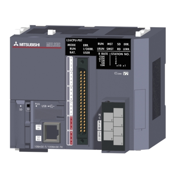
The following describes the parts names of the L series master/local modules. (1) L26CPU-BT For parts other than those for the built-in CC-Link functions, refer to the following manual. MELSEC-L CPU Module User's Manual (Hardware Design, Maintenance and Inspection) (2) LJ61BT11 2 - 1 2 - 1... - Page 26 2 PART NAMES Number Name Description LED indicators The data link status can be checked with each ON/OFF status. LED name Description On : Operating normally Off : Watchdog timer error L RUN On: Data link is being executed On: Operating as a master station. (in data link control) S MST On: Operating as a standby master station.
- Page 27 2 PART NAMES Station type and ON/OFF status of the "MST" and "S MST" LEDs Operating status Operating as a master station (data link control) Operating as a standby master station (standby) Standby master Standby master Master station Local station Master station Local station station...
-
Page 28: Specifications
The following shows the performance specifications of the L series master/local module. Specification Item Built-in CC-Link function LJ61BT11 Transmission speed Can be selected from 156 kbps/ 625 kbps/ 2.5 Mbps/ 5 Mbps/ 10 Mbps Maximum overall cable distance Varies according to the transmission speed (Refer to Section 3.2.2) - Page 29 3 SPECIFICATIONS (1) Number of link points in remote net ver.2 mode or remote net additional mode Item Specifications Remote I/O (RX/RY) : 8192 points Remote register (RWw) : 2048 points (master station remote device station/local station/intelligent device Maximum No. of link points per system station/standby master station) Remote register (RWr) : 2048 points (remote device station/local station/intelligent device station/standby...
-
Page 30: Maximum Number Of Connected Stations
3 SPECIFICATIONS 3.2.1 Maximum number of connected stations (1) Remote net ver.1 mode A total of 64 slave stations can be connected to a single master station. However, the following conditions must all be satisfied. a: Number of modules occupying 1 station b: Number of modules occupying 2 stations d)} ≤... - Page 31 3 SPECIFICATIONS (2) Remote net ver.2 mode, remote net additional mode A total of 64 slave stations can be connected to a single master station. However, the following conditions must all be satisfied. a: The total number of ver.1 compatible slave {(a + a2 + a4 + a8) stations that occupy 1 station, and ver.2 + (b + b2 + b4 + b8)
- Page 32 3 SPECIFICATIONS 3 - 5 3 - 5...
-
Page 33: Maximum Overall Cable Distance
3 SPECIFICATIONS 3.2.2 Maximum overall cable distance The relation of the transmission speed and maximum overcall cable distance when configuring the entire system with products compatible with CC-Link Ver.1.10 or higher and Ver.1.10 compatible CC-Link dedicated cables is shown below. For the identification of the CC-Link Version, refer to the installation manual issued by the CC-Link Partner Association. -
Page 34: Ver.1.10 Compatible Cc-Link Dedicated Cable
3 SPECIFICATIONS 3.2.3 Ver.1.10 compatible CC-Link dedicated cable Use Ver.1.10 compatible CC-Link dedicated cables for the CC-Link system. If a cable other than the Ver.1.10 compatible CC-Link dedicated cable is used, the performance of the CC-Link system cannot be guaranteed. For the specifications of the Ver.1.10 compatible CC-Link dedicated cables or any other inquiries, visit the following website: CC-Link Partner Association: http://www.cc-link.org/... -
Page 35: Function List
3 SPECIFICATIONS 3.3 Function List The following shows the function list of the L series master/local module. (1) List of the "basic functions" Item Description Reference Communication with remote I/O Performs on/off data communication with remote I/O stations. Section 8.1.1 stations Communication with remote device Performs on/off data and numeric data communication with... - Page 36 3 SPECIFICATIONS (3) List of the "handy functions" Item Description Reference Programs for the initial setting become unnecessary, since the initial settings in the remote device station are set at the network Remote device station initialization Section 8.3.1 parameter. The initial settings in the remote device station can procedure registration function be configured easily.
- Page 37 3 SPECIFICATIONS (4) List of the "functions for transient transmission" Item Description Reference Specifies a target and communicates with it at any timing when Transient transmission Section 9.1 required. 3 - 10 3 - 10...
-
Page 38: Mode Selection
3 SPECIFICATIONS 3.4 Mode Selection There are two different CC-Link versions: Ver.1 and Ver.2, and the L series master/local modules are Ver.2-compatible modules. The L series master/local modules have four types of modes for various systems. (1) Overview of the modes CC-Link Connectable station Mode... - Page 39 3 SPECIFICATIONS (2) Mode selection flowchart The following flowchart explains the points of mode selection. 3 - 12 3 - 12...
-
Page 40: Expanded Cyclic Setting
3 SPECIFICATIONS 3.4.1 Expanded cyclic setting When increasing the number of link points, select the remote net ver.2 mode or the remote net additional mode. (1) Remote net ver.2 mode This mode is designed to configure a new system. The number of link points can be increased as indicated below. Per station, RX/RY can be increased to up to 128 points and RWw/RWr to up to 32 points. - Page 41 3 SPECIFICATIONS Remote net additional mode This mode is designed for use when slave stations including a ver.2 compatible station is added to the existing ver.1 system. The program of the existing system can be used as is. Local station Remote device station Remote device station Remote I/O station...
- Page 42 3 SPECIFICATIONS (3) Mode combination (a) Whether system can be configured or not The following table indicates whether cyclic transmission can be made or not in each station. Slave station L series master/local module, A1SJ61BT11 QJ61BT11N, Remote station A1SJ61QBT11 Q81BD-J61BT11, Intelligent device station Q80BD-J61BT11N Standby...
- Page 43 3 SPECIFICATIONS 2 A link is performed as shown in the following areas. Local station Standby master station Local station Local station additional mode additional mode Ver. 1 mode Ver. 2 mode Master station (Station number 1: (Station number 2: (Station number 3: (Station number 7: Occupies 1 station)
- Page 44 3 SPECIFICATIONS (b) Whether send/receive is enabled or not The following table indicates whether send/receive of cyclic data is enabled or not. L series master/local module, Receive station QJ61BT11N Master station Ver.2 mode Additional mode Ver1 mode Ver.2 Ver.1 Ver.2 Ver.1 Ver.2 Ver.1...
- Page 45 3 SPECIFICATIONS L series master/local module, Intelligent device Remote Remote device statio QJ61BT11N station I/O station Local station Ver.2 mode Additional mode Ver1 mode Ver.2 Ver.1 Ver.2 Ver.1 Ver.1 Ver.2 Ver.1 Ver.2 Ver.1 Ver.2 Ver.1 compatible compatible compatible compatible compatible compatible compatible compatible...
-
Page 46: I/O Signal List
3 SPECIFICATIONS 3.5 I/O Signal List The following describes the I/O signal list of the L series master/local module. The "n" in the table indicates the master/local module's first I/O number of the L series, which is determined by both the installation position and the module installed before the L series master/local module. -
Page 47: Buffer Memory List
3 SPECIFICATIONS 3.6 Buffer Memory List The buffer memory is used for data exchange between the L series master/local module and a programmable controller CPU. Data can be read or written by parameter settings in GX Works2 or with dedicated instructions. - Page 48 3 SPECIFICATIONS Address Availability Read/write Item Description Reference Master Local possibility Hexadecimal Decimal station station For the master station: Stores the receive data Remote register from the remote (RWr) device/local/intelligent — Appendix Master station: Read only device/standby master 2 (3) For receiving stations.
- Page 49 3 SPECIFICATIONS Address Availability Read/write Item Description Reference Master Local possibility Hexadecimal Decimal station station For the master station: Stores the input status 4000 16384 — Ver.2 compatible from the slave stations. Read only remote input (RX) For the local station : Stores the input status 41FF 16895 —...
-
Page 50: Procedure Before Operation
4 PROCEDURE BEFORE OPERATION 4 PROCEDURE BEFORE OPERATION This chapter explains the procedure before operation. The following describes the procedure before operation. 4 - 1 4 - 1... - Page 51 4 PROCEDURE BEFORE OPERATION 4 - 2 4 - 2...
-
Page 52: System Configuration
5.1.1 System configuration of the L series master/local modules (1) When using the built-in CC-Link function Power supply module L26CPU-BT END cover (2) When using the LJ61BT11 (a) Connecting to the CPU module Power supply module L02CPU LJ61BT11 END cover... -
Page 53: System Configuration On Cc-Link
5 SYSTEM CONFIGURATION 5.1.2 System configuration on CC-Link The following shows a system configuration. 5 - 2 5 - 2... -
Page 54: Applicable System
Both of ver.1 and ver.2 compatible slave stations can be used. 5.2.2 Restrictions on use with the head module The following shows the restrictions when using the LJ61BT11 connected to the head module. (1) "Interrupt Setting" in Network Parameter is not available. -
Page 55: Precautions On The System Configuration
5 SYSTEM CONFIGURATION 5.2.3 Precautions on the system configuration The system should be designed with the following considerations to prevent mis-input from the remote I/O modules: (1) When powering on or off Start the data link after turning on the power to remote I/O modules. Turn off the power to remote I/O modules after stopping the data link. - Page 56 5 SYSTEM CONFIGURATION (b) Countermeasure for mis-input To the power supply module, the stabilized power supply and the external supply power of AC input, connect power cables from the same power source. For DC input For AC input REMARK When supplying power from a single power source to multiple remote I/O modules, select the proper type of cable and perform the wiring, taking into account a voltage drop.
- Page 57 5 SYSTEM CONFIGURATION (3) Access to station No.64 To a local station of No. 64, other station access from GX Works2 or GOT is not allowed. If the station No. is changed to any of 0 to 63, other station access is executable.
-
Page 58: Installation And Connection
6 INSTALLATION AND CONNECTION 6 INSTALLATION AND CONNECTION This chapter describes the installation and connection of the L series master/local modules. 6.1 Module Installation Environment and Position Refer to the following manual. MELSEC-L CPU Module User's Manual (Hardware Design, Maintenance and Inspection) MELSEC-L CC-Link IE Field Network Head Module User's Manual 6.1.1 Handling precautions... - Page 59 6 INSTALLATION AND CONNECTION (9) Solderless terminals with insulation sleeve cannot be used for the terminal block. It is recommended to cover the connection part of the solderless terminal with a marking tube or an insulation tube. (10) Before handling the module, touch a conducting object such as a grounded metal to discharge the static electricity from the human body.
-
Page 60: Hardware Test
6 INSTALLATION AND CONNECTION 6.2 Hardware Test The hardware test checks whether or not each module works properly by itself. Always perform this hardware test before configuring the system. POINT Be sure to execute the hardware test in the following status. (1) Perform this hardware test by itself and without connecting any CC-Link Ver.1.10 compatible cable. - Page 61 6 INSTALLATION AND CONNECTION 6 - 4 6 - 4...
-
Page 62: Connecting Modules With Ver.1.10 Compatible Cc-Link Dedicated Cables
6 INSTALLATION AND CONNECTION 6.3 Connecting Modules with Ver.1.10 Compatible CC-Link Dedicated Cables This section explains how to connect the master module, local modules, standby master module, remote modules and intelligent device modules with the Ver.1.10 compatible CC-Link dedicated cables. (1) Cables can be connected in any order, regardless of station numbers. - Page 63 6 INSTALLATION AND CONNECTION (8) The connection method is shown below. 6 - 6 6 - 6...
-
Page 64: Wiring Check
6 INSTALLATION AND CONNECTION 6.3.1 Wiring check The following explains how to check the wiring status between the remote I/O and external devices. [Example of wiring check] Specify the "Remote Input(RX)" for the master station to "X1000" and the “Remote Output(RY)"... - Page 65 6 INSTALLATION AND CONNECTION POINT If the X corresponding to the switch does not turn on or the lamp corresponding to the Y does not turn on, check the slave station offset, size information (buffer memory address 3E0 , Un\G992) for the RX/RY/RWw/RWr assignment status of the module.
-
Page 66: T-Branch Connection
6 INSTALLATION AND CONNECTION 6.4 T-Branch Connection 6.4.1 T-branch system configuration The following shows a system configuration using T-branch connection. T-branch terminal block/connector (Main line) Local station/ Remote I/O station/ Master Remote I/O station/ intelligent remote device station remote device station station device station (Branch line) -
Page 67: T-Branch Communication Specifications List
6 INSTALLATION AND CONNECTION 6.4.2 T-branch communication specifications list The following describes the communication specifications for T-branch connection. For communication specifications not listed below, refer to Section 3.2. Item Specification Remarks Transmission speed 625 kbps 156 kbps 10 M/5 M/2.5 Mbps are not allowed. Indicates the length of the cable between terminating Maximum length of the main line 100 m... -
Page 68: Loop Test
6 INSTALLATION AND CONNECTION 6.5 Loop Test Confirm that the master station and slave stations are correctly connected with the Ver.1.10 compatible CC-Link dedicated cables and that data linking can be performed. Loop test 1 checks the status of communication between the master station and all slave stations connected to the master station. -
Page 69: Loop Test 1
6 INSTALLATION AND CONNECTION 6.5.1 Loop test 1 Loop test 1 checks the connection status and the status of communication with slave stations. Perform the loop test 1 according to the following procedure. 6 - 12 6 - 12... - Page 70 6 INSTALLATION AND CONNECTION 6 - 13 6 - 13...
-
Page 71: Loop Test 2
6 INSTALLATION AND CONNECTION 6.5.2 Loop test 2 Loop test 2 checks whether data linking can be performed normally with a specified slave station. Perform the loop test 2 according to the following procedure. 6 - 14 6 - 14... - Page 72 6 INSTALLATION AND CONNECTION 6 - 15 6 - 15...
-
Page 73: Parameter Settings
7 PARAMETER SETTINGS 7 PARAMETER SETTINGS This chapter explains the parameter settings that are required to perform data link on the CC-Link. (1) Parameter setting method Two kinds of parameter setting are available: using GX Works2 or a dedicated instruction. (a) Parameter setting by using GX Works2 Using GX Works2 makes the setting of network parameters and automatic refresh parameters easier. - Page 74 7 PARAMETER SETTINGS POINT (1) If network parameters are set for modules on a system by both GX Works2 and the G(P).RLPASET instruction, the module(s) whose network parameters are set by the G(P).RLPASET instruction should not be included in the "Number of Modules"...
-
Page 75: Parameter List
7 PARAMETER SETTINGS 7.1 Parameter List The following shows the list of the network parameters and automatic refresh parameters. Mode Item Reference Remote net Remote net Remote net Remote I/O net ver.1 mode ver.2 mode additional mode mode Start I/O No. ――... -
Page 76: Parameter Settings In Remote Net Ver.1 Mode
7 PARAMETER SETTINGS 7.2 Parameter Settings in Remote Net Ver.1 Mode This section explains the parameter settings using GX Works2. The following shows the network parameter screen. The following shows the setting items of the network parameter screen. Standby Master Local Item Description... - Page 77 7 PARAMETER SETTINGS Standby Master Local Item Description Master Reference station station station Set the module station number Default value: 0 Setting range [Master station] Section Station No. [Master station (Duplex function)] 7.2 (1) : 0 to 64 [Local station and standby master station] : 1 to 64 Set the CC-Link mode to "Remote Net (Ver.1 Mode)".
- Page 78 7 PARAMETER SETTINGS Standby Master Local Item Description Master Reference station station station Set the link special relay (SB) refresh device. Default value: Blank Special Relay (SB) Setting range: Device name - Select from M, L, B, D, W, R, SB or ZR. ――...
- Page 79 7 PARAMETER SETTINGS POINT (1) The network parameters other than operation setting, station No., mode and transmission speed are also valid when the programmable controller CPU is switched from STOP to RUN. (2) When changing the parameters and settings of master station or slave station, stop the data link at the master station and then make the changes.
- Page 80 7 PARAMETER SETTINGS (1) Station number setting The following explains how to set the station numbers for the master station and slave stations. Specify the station numbers according to the following conditions. (a) Specify sequential station numbers Station numbers can be specified regardless of the order in which the stations are connected.
- Page 81 7 PARAMETER SETTINGS (2) Transmission speed Set the transmission speed of the master station, the local station and the standby master station. For using the module as a local station or standby master station, the transmission speed can be set to "Auto following". In that case, since the local station or standby master station follows the transmission speed of the master station automatically, no transmission speed setting error will occur.
-
Page 82: Operation Setting
7 PARAMETER SETTINGS 7.2.1 Operation setting The following shows the Operation Setting screen. The following shows the setting items of the Operation Setting screen. Standby Master Local Item Description Master Reference station station station Set the Parameter name. (Even if the Parameter name is not set, this will not affect the operation of the CC-Link system). -
Page 83: Station Information Setting
7 PARAMETER SETTINGS 7.2.2 Station information setting The following shows the Station Information screen. The following shows the setting items of the Station Information screen. Standby Master Local Item Description Master Reference station station station Set the station type of the slave station. Default value: Remote I/O Station Setting range: No Setting Station Type... - Page 84 7 PARAMETER SETTINGS POINT For the communication buffer size, specify the size of the data to be sent or received. For the automatic update buffer size, specify the size required for each intelligent device station. Example) Enter station information on the following system configuration. Station number 4 Station...
-
Page 85: Parameter Settings In Remote Net Ver.2 Mode
7 PARAMETER SETTINGS 7.3 Parameter Settings in Remote Net Ver.2 Mode This section explains the parameter settings using GX Works2. The following shows the network parameter screen. The following shows the setting items of the network parameter screen. Standby Master Local Item Description... - Page 86 7 PARAMETER SETTINGS Standby Master Local Item Description Master Reference station station station Set the module station number. Default value: 0 Setting range [Master station] Section Station No. [Master station (Duplex function)] 7.2 (1) : 0 to 64 [Local station and standby master station] : 1 to 64 Set the CC-Link mode to "Remote Net (Ver.2 Mode)".
- Page 87 7 PARAMETER SETTINGS Standby Master Local Item Description Master Reference station station station Set the link special relay (SB) refresh device. Default value: Blank Special Relay (SB) Setting range: Device name - Select from M, L, B, D, W, R, SB or ZR. ――...
- Page 88 7 PARAMETER SETTINGS POINT (1) The network parameters other than operation setting, station No., mode and transmission speed are also valid when the programmable controller CPU is switched from STOP to RUN. (2) When changing the parameters and settings of the master station or slave station, stop the data link at the master station and then make the changes.
- Page 89 7 PARAMETER SETTINGS 7.3.1 Operation setting The following shows the Operation Setting screen. The following shows the setting items of the Operation Setting screen. Standby Master Local Item Description Master Reference station station station Set the Parameter name. (Even if the Parameter name is not set, this will not affect the operation of the CC-Link system).
-
Page 90: Station Information Setting
7 PARAMETER SETTINGS 7.3.2 Station information setting The following shows the Station Information screen. The following shows the setting items of the Station Information screen. Standby Master Local Item Description Master Reference station station station Set the station type of the slave station. Default value: Ver.1 Remote I/O Station Setting range: No Setting Ver.1 Remote I/O Station... - Page 91 7 PARAMETER SETTINGS Standby Master Local Item Description Master Reference station station station Set the number of remote station points of slave stations. Default value: 32 Points Setting range [When station type is ver.1 remote I/O station] : 0 Points (Reserved Station) 8 Points 8 Points + 8 Points (Reserved) 16 Points...
- Page 92 7 PARAMETER SETTINGS Example) Enter station information on the following system configuration. Station Station Station number 4 number 2 number 9 Ver. 2 Ver. 2 Ver. 1 Station Station compatible compatible compatible number 8 number 1 local station remote device Master station intelligent station...
-
Page 93: Parameter Settings In Remote Net Additional Mode
7 PARAMETER SETTINGS 7.4 Parameter Settings in Remote Net Additional Mode This section explains the parameter settings using GX Works2. The following shows the network parameter screen. The following shows the setting items of the network parameter screen. Standby Master Local Item Description... - Page 94 7 PARAMETER SETTINGS Standby Master Local Item Description Master Reference station station station Set the module station number. Default value: 0 Setting range [Master station] Section Station No. [Master station (Duplex function)] 7.2 (1) : 0 to 64 [Local station and standby master station] : 1 to 64 Set the CC-Link mode to "Remote Net (Additional Mode)".
- Page 95 7 PARAMETER SETTINGS Standby Master Local Item Description Master Reference station station station Set the refresh device of the Ver.2 compatible remote input (RX). Default value: Blank Ver.2 Remote Input (RX) Setting range: Device name - Select from X, M, L, B, D, W, R or ZR. ――...
- Page 96 7 PARAMETER SETTINGS Standby Master Local Item Description Master Reference station station station Set whether the link scan for the sequence scan is synchronous or asynchronous. Section Scan Mode Setting Default value: Asynchronous 8.3.7 Setting range: Asynchronous Synchronous ―― Delay Time Setting Set 0.
- Page 97 7 PARAMETER SETTINGS POINT (1) The network parameters other than operation setting, station No., mode and transmission speed are also valid when the programmable controller CPU is switched from STOP to RUN. (2) When changing the parameters and settings of the master station or slave station, stop the data link at the master station and then make the changes.
- Page 98 7 PARAMETER SETTINGS 7.4.1 Operation setting The following shows the Operation Setting screen. The following shows the setting items of the Operation Setting screen. Standby Master Local Item Description Master Reference station station station Set the Parameter name. (Even if the Parameter name is not set, this will not affect the operation of the CC-Link system).
-
Page 99: Station Information Setting
7 PARAMETER SETTINGS 7.4.2 Station information setting The following shows the Station Information screen. The following shows the setting items of the Station Information screen. Standby Master Local Item Description Master Reference station station station Set the station type of the slave station. Default value: Ver.1 Remote I/O Station Setting range: No setting Ver.1 Remote I/O Station... - Page 100 7 PARAMETER SETTINGS Standby Master Local Item Description Master Reference station station station Set the remote station points of the slave station. Default value: 32 Points Setting Range: 32 Points [when exclusive station 1] (cannot be changed) Remote Station Points 64 Points [when exclusive station 2] (cannot be changed) 96 Points [when exclusive station 3] (cannot be changed) 128 Points [when exclusive station 4] (cannot be changed)
- Page 101 7 PARAMETER SETTINGS Example) Enter station information on the following system configuration. Station Station Station Station number 2 number 4 number 9 number 8 Ver. 2 Ver. 2 Ver. 2 Ver. 1 Station compatible compatible compatible compatible remote number 1 intelligent local station Master station...
-
Page 102: Parameter Settings In Remote I/O Net Mode
7 PARAMETER SETTINGS 7.5 Parameter Settings in Remote I/O Net Mode This section explains the parameter settings using GX Works2. The following shows the network parameter screen. The following shows the setting items of the network parameter screen. Standby Master Local Item Description... - Page 103 7 PARAMETER SETTINGS Standby Master Local Item Description Master Reference station station station Set the total number of connected stations in the CC-Link system including reserved stations for "Total Module Connected". Total Module Connected ―― Default value: 64 (modules) Setting range: 1 to 64 (modules) Set the remote input (RX) refresh device.
- Page 104 7 PARAMETER SETTINGS POINT (1) The network parameters other than operation setting, station No., mode and transmission speed are also valid when the programmable controller CPU is switched from STOP to RUN. (2) When changing the parameters and settings of the master station or slave station, stop the data link at the master station and then make the changes.
-
Page 105: Operation Setting
7 PARAMETER SETTINGS 7.5.1 Operation setting The following shows the Operation Setting screen. The following shows the setting items of the Operation Setting screen. Standby Master Local Item Description Master Reference station station station Set the Parameter name. (Even if the Parameter name is not set, this will not affect the operation of the CC-Link system). -
Page 106: Precautions On Parameter Setting
7 PARAMETER SETTINGS 7.6 Precautions on Parameter Setting (1) Mismatch in number of points between parameter-set expanded cyclic setting and installation status If there is a mismatch in the number of points between the parameter-set expanded cyclic setting and installation status, the L series master/local module stores an error code into SW0069. -
Page 107: Functions
8 FUNCTIONS 8 FUNCTIONS This chapter explains the functions of the L series master/local module, dividing them into three sections: "Basic Functions", "Functions for Improving System Reliability" and "Handy Functions". 8.1 Basic Functions This section explains the basic functions of the L series master/local module. 8.1.1 Communication with remote I/O stations The following is an overview of the communication between the master station and a remote I/O station using the remote I/O net mode. - Page 108 8 FUNCTIONS [Remote input] 2) The input status of a remote I/O station is stored automatically (for each link scan) in the master station's "remote input RX" buffer memory. 3) The input status stored in the "remote input RX" buffer memory is stored in the CPU device set with the automatic refresh parameters.
-
Page 109: Communication With Remote Device Stations
8 FUNCTIONS 8.1.2 Communication with remote device stations This section explains an overview of the communication between the master and remote device stations. In the communication with remote device stations, the signals for handshaking with remote device stations (initial data request flag, error reset request flag, etc.) are communicated using remote input RX and remote output RX. - Page 110 8 FUNCTIONS [Data link startup] 1) When the programmable controller system is powered on, the network parameters in the programmable controller CPU are transferred to the master station, and the CC-Link system automatically starts up. [Remote input] 2) The remote input RX of a remote device station is stored automatically (for each link scan) in the master station's "remote input RX"...
- Page 111 8 FUNCTIONS [Remote output] 4) The on/off data of the CPU device set with the automatic refresh parameters is stored in the "remote output RY" buffer memory. 5) Remote output RY is automatically set to on/off (for each link scan) according to the output status stored in the "remote output RY"...
- Page 112 8 FUNCTIONS [Writing to the remote register RWw] 6) The transmission data of the CPU device set with the automatic refresh parameters is stored in the "remote register RWw" buffer memory. 7) The data stored in the "remote register RWw" buffer memory is automatically sent to the remote register RWw of each remote device station.
- Page 113 8 FUNCTIONS [Reading from the remote register (RWr)] 8) The remote register RWr data of a remote device station is automatically stored in the "remote register Rwr" buffer memory of the master station. 9) The remote register RWr data of a remote device station stored in the "remote register RWr"...
-
Page 114: Communication With Local Stations
8 FUNCTIONS 8.1.3 Communication with local stations This section explains an overview of the communication between the master and local stations. (1) Communication between the master and local stations by cyclic transmission Data communication between programmable controller CPUs can be performed in N:N mode using remote input RX and remote output RY (bit data used in local station systems) as well as remote register RWw and remote register RWr (word data for writing and reading used in local station systems). - Page 115 8 FUNCTIONS [Data link startup] 1) When the programmable controller system is powered on, the network parameters in the programmable controller CPU are transferred to the master station and the CC-Link system starts up automatically. [On/off data from a local station to the master station or other local stations] 2) The on/off data of the CPU device set with the automatic refresh parameters is stored in the "remote output RY"...
- Page 116 8 FUNCTIONS [On/off data from the master station to local stations] 6) The on/off data of the CPU device set with the automatic refresh parameters is stored in the "remote output RY" buffer memory of the master station. 7) The data in the "remote output RY" buffer memory is stored automatically (for each link scan) in the "remote input RX"...
- Page 117 8 FUNCTIONS [Word data from the master station to all local stations] 9) The word data of the CPU device set with the automatic refresh parameters is stored in the "remote register RWw" buffer memory of the master station. The remote register RWw is used as word data for writing in local station systems.
- Page 118 8 FUNCTIONS [Word data from a local station to the master and other local stations] 12) Word data set with the automatic refresh parameters is stored in the "remote register RWw" buffer memory of the local station. However, the data is stored only in the area corresponding to its own station number. 13) The data in the "remote register RWw"...
- Page 119 8 FUNCTIONS (2) Communication between the master and local stations by transient transmission Transient transmission is one of the transmission methods, and by which data are sent or received at any timing on a one-to-one basis (1:1) by specifying the target.
- Page 120 8 FUNCTIONS POINT Before performing data communication using transient transmission, the sizes of the send and receive buffers must be set up in the buffer memory of the master station. For details on setting the sizes of the send and receive buffers, refer to Sections 7.2.2, 7.3.2 and 7.4.2.
-
Page 121: Communication With Intelligent Device Stations
8 FUNCTIONS 8.1.4 Communication with intelligent device stations This section explains an overview of the communication between the master and intelligent device stations. (1) Communication between the master station and intelligent device stations by cyclic transmission Handshaking signals with intelligent device stations (positioning complete, positioning start. - Page 122 8 FUNCTIONS [Data link startup] 1) When the programmable controller system is powered on, the network parameters in the programmable controller CPU are transferred to the master station, and the CC-Link system automatically starts up. [Remote input] 2) The remote input RX of an intelligent device station is stored automatically (for each link scan) in the master station's "remote input RX"...
- Page 123 8 FUNCTIONS [Remote output] 4) The on/off data of the CPU device set with the automatic refresh parameters is stored in the "remote output RY" buffer memory. 5) Remote output RY of the intelligent device station is automatically set to on/off (for each link scan) according to the output status stored in the "remote output RY"...
- Page 124 8 FUNCTIONS [Writing to the remote register (RWw)] 6) The transmission data of the CPU device set with the automatic refresh parameters is stored in the "remote register RWw" buffer memory. 7) The data stored in the "remote register RWw" buffer memory is automatically sent to the remote register RWw of the intelligent device station.
- Page 125 8 FUNCTIONS [Reading from the remote register (RWr)] 8) The remote register RWr data of the intelligent device station is automatically stored in the "remote register Rwr" buffer memory of the master station. 9) The remote register RWr data of the intelligent device station stored in the "remote register RWr"...
- Page 126 8 FUNCTIONS (2) Communication between the master and intelligent device stations by transient transmission Transient transmission is one of the transmission methods, and by which data are sent or received at any timing on a one-to-one basis (1:1) by specifying the target.
- Page 127 8 FUNCTIONS POINT Before performing data communication using transient transmission, the sizes of the send and receive buffers must be set up in the buffer memory of the master station. For details on setting the sizes of the send and receive buffers, refer to Sections 7.2.2, 7.3.2 and 7.4.2.
-
Page 128: Functions For Improving System Reliability
8 FUNCTIONS 8.2 Functions for Improving System Reliability This section explains the functions for improving the reliability of the CC-Link system. 8.2.1 Slave station cut-off function This function disconnects a slave station that has gone down due to a cause such as power off, and continues the data link among only normal slave stations (no setting is required). -
Page 129: Automatic Return Function
8 FUNCTIONS 8.2.2 Automatic return function This function allows a slave station that has been disconnected from the data link due to a cause such as power off to be automatically reconnected to the data link when it returns to the normal status. [Setting method] Set a value for "Automatic Reconnection Station Count"... -
Page 130: Data Link Status Setting In Case Of Master Station Programmable Controller Cpu Failure
8 FUNCTIONS 8.2.3 Data link status setting in case of master station programmable controller CPU failure This function sets the data link status (stop/continue) in case that an "error that stops the operation" occurs in the master station programmable controller CPU when the system does not have a standby master station. -
Page 131: Setting The Status Of Input Data From A Data Link Faulty Station
8 FUNCTIONS 8.2.4 Setting the status of input data from a data link faulty station This function sets whether to clear or retain the input data (remote input (RX)) from data link faulty stations. For the status of each station at error occurrence, refer to Section 8.2.6. (1) Target input (receiving) data The following shows the applicable buffer memory areas. - Page 132 8 FUNCTIONS (2) Setting method Set a mode in "Operation Setting" – "Data Link Disorder Station Setting" in the Network Parameter setting of GX Works2. (Refer to Sections 7.2.1, 7.3.1, 7.4.1, and 7.5.1.) 8 - 26 8 - 26...
-
Page 133: Slave Station Refresh/Compulsory Clear Setting In Case Of Programmable Controller Cpu Stop
8 FUNCTIONS 8.2.5 Slave station refresh/compulsory clear setting in case of programmable controller CPU STOP This function forcibly clears the output data (remote output RY) to slave stations when the programmable controller CPU comes to STOP. Remote output RY refresh device setting in the automatic refresh parameter dialog box provides the following choices. - Page 134 8 FUNCTIONS POINT (1) Selecting the compulsory clear option disables compulsory output to slave stations at CPU STOP using GX Works2. (2) This setting is also valid when the TO instruction is used for RY refresh. (2) Setting method Set a mode in "Operation Setting" – "Case of CPU STOP Setting" in the Network Parameter setting of GX Works2.
-
Page 135: Station Status At Error Occurrence
8 FUNCTIONS 8.2.6 Station status at error occurrence This section explains the status of each station that is set in Network Parameter’s "PLC Down Select" and "Operation Setting" in case of error occurrence. (Refer to Sections 8.2.3, 8.2.4 and 8.2.5.) (1) Status of the master station, standby master station (acting as a master station) and remote I/O station at error occurrence The following shows the operations of the master station, standby master station... - Page 136 8 FUNCTIONS (2) Status of the remote device station, local station, standby master station (acting as a local station) and intelligent device station at error occurrence The following shows the status of the remote device station, local station, standby master station (acting as a local station) and intelligent device station at error occurrence.
-
Page 137: Standby Master Function
8 FUNCTIONS 8.2.7 Standby master function This function enables the data link to continue working by switching the control to the standby master station (meaning a backup station for the master station) if a system down occurs in the master station due to a malfunction in the programmable controller CPU or power supply. - Page 138 8 FUNCTIONS 1 When the master station goes down and the data link control is switched to the standby master station, the station number of the standby master station becomes "0". 2 When the master station returns as a standby master station, the station number of the master station becomes the one specified in the “Standby Master Station No."...
- Page 139 8 FUNCTIONS 8 - 33 8 - 33...
- Page 140 8 FUNCTIONS (1) Overview of link data transmission when the standby master function is used The following shows an overview of link data transmission when the standby master function is used. (a) When the master station controls the data link 1) Master station output Standby master station (standby) Station number 1...
- Page 141 8 FUNCTIONS (b) When the master station is faulty and the standby master station is controlling the data link 1) Standby master station output Standby master station (controlling) Station number 1 Master station Remote Remote Remote Remote Remote I/O station input RX output RY input RX...
- Page 142 8 FUNCTIONS (c) When the master station returns to system operation and the standby master station is controlling the data link 1) Standby master station output Master station (standby) Standby master station Station number 0 (controlling) Occupies 1 station Station number 0 Remote Remote Remote...
- Page 143 8 FUNCTIONS (d) When the standby master station becomes faulty and the master station controls the data link 1) Master station output Master station (controlling) Standby master station Station number 1 Remote Remote Remote Remote input RX output RY input RX output RY Remote I/O station Station number 2...
- Page 144 8 FUNCTIONS (2) Setting method Perform the setting using GX Works2. (a) Setting the master station First, set "Type" in the Network Parameter setting. Master station that was down returns to system operation: Master Station (Duplex Function) Master station that was down does not return to system operation: Master Station Next, set the "Standby Master Station No."...
- Page 145 8 FUNCTIONS (3) Precautions on using the standby master function (a) Only one standby master station exists in a single data link system. (b) If an error is detected at the master station in the initial status (before parameter communication starts), switching to the standby master station will not be executed.
- Page 146 8 FUNCTIONS (4) Link special relays/registers (SB and SW) relating to the standby master function The following shows the list of the link special relays and registers relating to the standby master function. For details, refer to Appendix 3. Link special relay/register Number Name SB0001...
- Page 147 8 FUNCTIONS (5) On/off timings of link special relays (SB) relating to the standby master function The following shows the on/off timings of the link special relays (SB) relating to the standby master function. When SB005B is turned on, the program switches RX to RY and RWr to RWw. In addition, the program turns SB0001 on.
- Page 148 8 FUNCTIONS (6) Program example when the standby master function (master station duplex function) is used A program example is created under the following conditions when the standby master function (master station duplex function) is used. (a) System configuration (b) Parameter settings of the master station (c) Parameter settings of the standby master station 8 - 42 8 - 42...
- Page 149 8 FUNCTIONS (d) Program example when standby master function (master station duplex function) is used Control start relay used when master station is operating....M10 Control start relay used when standby master station is operating..M11 Control start relay when the master station is operating Initial device set Control start relay when the station...
-
Page 150: Data Link Start By Standby Master Station
8 FUNCTIONS 8.2.8 Data link start by standby master station This function allows data link to start by turning on either of the master or standby master station. When the standby master station is turned on, even if no power is applied to the master station, data link will start. - Page 151 8 FUNCTIONS 8 - 45 8 - 45...
- Page 152 8 FUNCTIONS (1) Setting method The following shows how to make settings. (a) Set station No.0 for the master station, and any of station 1 to 64 for the standby master station. (b) Configure the same system (the same programmable controller CPU, I/O modules, and/or intelligent function modules) for the master and standby master stations.
-
Page 153: Block Guarantee Of Cyclic Data Per Station
8 FUNCTIONS 8.2.9 Block guarantee of cyclic data per station This function allows guaranteeing the consistency of the cyclic data for each slave station according to the parameter setting. To ensure the consistency of data exceeding two words, use this function. When this function is not used, cyclic data may be separated into new data and old data in 2-word (32-bit) units, depending on the auto refresh timing. - Page 154 8 FUNCTIONS The following example shows the range in which data of remote register RWw are guaranteed when this function is set in the remote net Ver.2 mode. Programmable Remote station Master station controller CPU Station number 1 Remote register Device RWw0 Automatic...
- Page 155 8 FUNCTIONS (1) Setting method The following describes the setting method. (a) Click the Operation Setting button in the Network Parameter setting in GX Works2. (b) The [Operation Setting] screen is displayed. Check the [Block Data Assurance per Station] checkbox. (c) Make the auto refresh settings for each remote device.
- Page 156 8 FUNCTIONS (2) Precautions when using the block guarantee of cyclic data per station (a) When using this function, be sure to make the auto refresh settings. If the auto refresh settings have not been made for all devices, remote input (RX), remote output (RY) and remote registers (RWr/RWw) in the buffer memory may not be refreshed.
-
Page 157: Secured 32-Bit Data
8 FUNCTIONS 8.2.10 Secured 32-bit data When the following conditions, 1) and 2) are satisfied in the CC-Link network, 32-bit data in remote registers (RWr/RWw) between a programmable controller CPU and a master/local station can be secured. 1) Access starts from a remote resister (RWr/RWw) address of an "even number". Programmable Programmable controller CPU... -
Page 158: Handy Functions
8 FUNCTIONS 8.3 Handy Functions This section explains some handy functions of the L series master/local module. 8.3.1 Remote device station initialization procedure registration function The initial settings of remote device stations can be performed using GX Works2 for registration to the programmable controller CPU. The L series master/local module instructs registration or remote device station initialization procedure (SB000D) and then stores the number of the currently executing procedure to the buffer memory. - Page 159 8 FUNCTIONS (2) Remote device station initialization procedure setting method Configure the settings in "Remote Device Station Initial Setting" in the Network Parameter setting. For setting examples using GX Works2, refer to Sections 11.1.2 (4), 11.2.2 (4), and 11.3.2 (4). (a) In "Target Station No.", set the station number of the module for which the initial settings are to be performed.
- Page 160 8 FUNCTIONS 3) Operational condition Specify whether new settings or the previous settings are used for the initial setting operating conditions. Setting range: Set New Same as Prev. Set Default: Set New When "Same as Prev. Set" is selected, the processing is performed as follows: Example) RWw2...
- Page 161 8 FUNCTIONS 9) Details of execution "Write Data" Set the contents of the initial settings. Setting range: When RY is selected ON/OFF When RWw is selected 0 to 65535 (Decimal), 0 to FFFF (Hexadecimal) The following shows the procedure registration screen appeared after setting of (1) to (9).
- Page 162 8 FUNCTIONS (3) Method for initializing only a specified station (specification of remote device station to be initialized) When a running remote device station is replaced due to a failure, initial processing that has been done for all stations conventionally can be performed for the replaced remote device station by specifying it.
- Page 163 8 FUNCTIONS (4) Enable initial settings Before creating a program for communication with remote device stations, create a program to enable the initial settings using SB000D (remote device station initialization procedure registration instruction) and SB005F (completion status of remote device station initialization procedure execution). For details, refer to Sections 11.1.3, 11.2.3 and 11.3.3.
- Page 164 8 FUNCTIONS (5) Preparation for communication with remote device stations 1) Register the network parameters and the created program in the programmable controller CPU. 2) Reset the programmable controller CPU or power it off and then on. 3) Instruct the master station to register the remote device station initialization procedure (SB000D).
- Page 165 8 FUNCTIONS (6) Link special relays and registers (SB/SW) relating to remote device station initialization procedure registration The following shows the list of the link special relays and registers relating to the remote device station initialization procedure registration. For more details, refer to Appendix 3. Link special relay/register Number Name...
-
Page 166: Event Issuance For The Interrupt Program
8 FUNCTIONS 8.3.2 Event issuance for the interrupt program This function issues events (signals to execute an interrupt program) according to factors such as the on/off status of specified RX, RY and SB devices and the match/mismatch status of specified RWr and SW device data, in order to allow the programmable controller CPU to execute the interrupt program. - Page 167 8 FUNCTIONS 5) Interrupt condition Set the conditions under which events are issued. Setting range: When RX, SB or RY is selected ON/OFF When RWr or SW is selected Equal/Unequal 6) Word device setting value Set the conditions under which events are issued when RWr or SW is selected.
- Page 168 8 FUNCTIONS 4) "Start SI No." on the intelligent module side Set the smallest number for intelligent function module interrupt pointers specified in "Interrupt (SI) No." of the "Interrupt Setting" in the Network Parameter setting. Setting range: 0 to 15 (3) Simulation of the interrupt program When the event issuance conditions are established in the master station using GX Works2, the interrupt program is executed even when the corresponding...
-
Page 169: Automatic Cc-Link Startup
8 FUNCTIONS 8.3.3 Automatic CC-Link startup When in a system configuration including not only remote I/O stations but also remote device stations and intelligent device stations, the CC-Link startup and data refresh are performed only by powering up the system and without creating a program for it. Use this function to check the operation when constructing a system. - Page 170 "LJ61BT11". Even when more than one LJ61BT11 is mounted, the automatic CC-Link startup function is applicable only to the first one. It is applied to the LJ61BT11 that has the smallest start I/O number, as seen from the programmable controller CPU side.
-
Page 171: Reserved Station Function
8 FUNCTIONS 8.3.4 Reserved station function This function prevents slave stations that are not actually connected (but to be connected in the future) from being treated as "data link faulty stations" by the master station and local stations. When the master station is placed in the remote net ver.2 mode, points for reserved stations can be set to 0. -
Page 172: Error Invalid Station Setting Function
8 FUNCTIONS 8.3.5 Error invalid station setting function This function prevents slave stations that are powered off in the system configuration from being treated as "data link faulty stations" by the master station and local stations, using the network parameter settings. Note that if a station is set as an error invalid station, problems occurring in that station can no longer be detected. -
Page 173: Temporary Error Invalid Station Setting Function
8 FUNCTIONS 8.3.6 Temporary error invalid station setting function This function allows the replacement of modules while online, without error detection. Also, this function prevents slave stations, which are turned off in the system configuration, from being treated as "data link faulty stations" temporarily. (1) Setting method Set the [Diagnostics] [CC-Link Diagnostics] using GX Works2. - Page 174 8 FUNCTIONS (2) Precautions (a) Precautions when temporary error invalid station setting is executed Do not write to buffer memory addresses 5E0 , and 603 to 607 Do not execute at one time by programs and other peripherals. If executed at one time, temporary error invalid station setting may not operate normally.
-
Page 175: Scan Synchronous Function
8 FUNCTIONS 8.3.7 Scan synchronous function This function selects whether to synchronize or not the link scan with the sequence scan. (1) Synchronous mode Performs data linking using the scan that is synchronized with the program. (The sequence scan and link scan start at the same time.) In the synchronous mode, the link scan interval becomes longer when the sequence scan takes long because the link scan is synchronized with the sequence scan. - Page 176 8 FUNCTIONS (4) Data flows in synchronous and asynchronous modes The data flows in both the synchronous and asynchronous modes are explained using examples of communications between the master station and remote I/O stations. (a) Data flow in the asynchronous mode I: Delay time due to response delay of remote I/O station II: Delay time of transmission from the remote I/O station to the master station...
- Page 177 8 FUNCTIONS (b) Data flow in the synchronous mode 1) Sequence scan > Link scan I: Delay time due to response delay of remote I/O station II: Delay time of transmission from the remote I/O station to the master station III: Delay time from reception by the master station to storage in the buffer memory IV: Delay time until the master station's information is refreshed in the...
- Page 178 8 FUNCTIONS 2) Sequence scan < Link scan I: Delay time due to response delay of remote I/O station II: Delay time of transmission from the remote I/O station to the master station III: Delay time from reception by the master station to storage in the buffer memory IV: Delay time until the master station's information is refreshed in the programmable controller CPU...
-
Page 179: Data Link Stop/Restart
8 FUNCTIONS 8.3.8 Data link stop/restart This function stops and restarts local data links. If the data link is stopped, programs can be efficiently debugged, since other stations data are not received and host station data are not sent. If the data link of the master station is stopped, the data link of the entire system stops. (1) Setting method Set the [Diagnostics] [CC-Link Diagnostics] using GX Works2. - Page 180 8 FUNCTIONS (2) Precautions (a) Precautions when executing data link stop/restart Do not write to buffer memory address 5E0 Do not execute at one time by programs and other peripherals. If executing at one time, data link stop/restart may not operate normally. (b) If executing "Stop Data Link"...
-
Page 181: Remote I/O Station Points Setting
8 FUNCTIONS 8.3.9 Remote I/O station points setting The points of each remote I/O station can be set to 8, 16 or 32 points. This saves the refresh device points of the programmable controller CPU and link refresh time. The remote I/O station points setting can be used in the remote net ver. 2 mode only. For parameter setting, use GX Works2. - Page 182 8 FUNCTIONS [Setting method] Using GX Works2, make setting by choosing "Station Information Setting" - "Remote Station Points" in the Network Parameter dialog box. (Refer to Section 7.3.2) (1) Precautions for setting the remote I/O station points The number of parameter-set remote I/O station points should be equal to or greater than the number of I/O points of the mounted remote I/O stations.
-
Page 183: Master Station Duplication Error Cancel Function
8 FUNCTIONS 8.3.10 Master station duplication error cancel function This function cancels a master station duplication error without turning the power supply off to on, or without resetting the programmable controller CPU, if a master station duplication error is detected. (1) Removing the cause of error occurrence Before performing the master station duplication error cancel function, remove the cause of error occurrence of the master station duplication error. -
Page 184: Dedicated Instructions And Programming
9. DEDICATED INSTRUCTIONS AND PROGRAMMING 9. DEDICATED INSTRUCTIONS AND PROGRAMMING The following explains precautions on dedicated instructions and programming. 9.1 Dedicated Instructions Using dedicated instructions, the L series master/local module is capable of the following: • Transient transmission to local stations and intelligent device stations •... - Page 185 9. DEDICATED INSTRUCTIONS AND PROGRAMMING POINT Execute the dedicated instructions while the data link is being performed. If any of the dedicated instructions is executed offline, no error will occur, but the execution of the dedicated instruction will not be completed. (2) Available devices The following devices are available for the dedicated instructions: Internal devices...
-
Page 186: G(P).Rird
9. DEDICATED INSTRUCTIONS AND PROGRAMMING 9.1.2 G(P).RIRD The G(P).RIRD instruction reads the specified points of data from the buffer memory or the programmable controller CPU device of the specified station. Usable devices Internal device Link direct device Intelligent Constant Index (System, user) function Set data... - Page 187 9. DEDICATED INSTRUCTIONS AND PROGRAMMING Control data Device Item Set data Setting range Set by Stores the status when the instruction is complete. (S) + 0 Completion status : No error (normal completion) — System Other than 0: Error code Specify the station numbers of the master station, local (S) + 1 Station number...
- Page 188 9. DEDICATED INSTRUCTIONS AND PROGRAMMING (1) Buffer memory in the CC-Link Buffer Memory contents Access code Attribute code Buffer in the intelligent device station Random access buffer Remote input Buffers in master station and local Remote output station Remote register Link special relay Link special register (2) Device memory in the programmable controller CPU...
- Page 189 9. DEDICATED INSTRUCTIONS AND PROGRAMMING (3) Functions (a) Operation chart for the RIRD instruction Master station Specified station Programmable controller CPU Master module Local module Programmable controller CPU Command G(P).RIRD Buffer memory Device memory Device memory Receive buffer 1) Accesses the buffer memory specified by (S)+2 and (S)+3 of the station specified by (S)+1, or the programmable controller CPU device.
- Page 190 9. DEDICATED INSTRUCTIONS AND PROGRAMMING (c) There are two types of interlock signals for the G(P).RIRD instruction: the completion device (D2) and status display device at completion (D2) + 1. 1) Completion device Turns ON in the END processing of the scan where the G(P).RIRD instruction is completed, and turns OFF in the next END processing.
- Page 191 9. DEDICATED INSTRUCTIONS AND PROGRAMMING (5) Program example When X0 is turned ON, 10-word data are stored from the area starting D1000 in a local station (station No.1), which is connected to the master module in the I/O No. position of X/Y40 to X/Y5F, into the area starting from D0. (When the link special register (SW) refresh device is set to SW0000) M12 is the RIRD instruction executing flag.
-
Page 192: G(P).Riwt
9. DEDICATED INSTRUCTIONS AND PROGRAMMING 9.1.3 G(P).RIWT The G(P).RIWT instruction writes the specified points of data, to the buffer memory or the programmable controller CPU device of the specified station. Usable devices Internal device Link direct device Intelligent Constant (System, user) function Index Set data... - Page 193 9. DEDICATED INSTRUCTIONS AND PROGRAMMING Control data Device Item Set data Setting range Set by Stores the status when the instruction is complete. (S1) + 0 Completion status : No error (normal completion) — System Other than 0: Error code Specify the station numbers of the master station, local (S1) + 1 Station number...
- Page 194 9. DEDICATED INSTRUCTIONS AND PROGRAMMING (1) Buffer memory in the CC-Link Buffer Memory contents Access code Attribute code Buffer in the intelligent device station Random access buffer Remote input Buffers in master station and local Remote output station Remote register Link special relay Link special register (2) Device memory in the programmable controller CPU...
- Page 195 9. DEDICATED INSTRUCTIONS AND PROGRAMMING (3) Functions (a) Operation chart for the G(P).RIWT instruction Master station Specified station Programmable controller CPU Master module Local module Programmable controller CPU Command G(P).RIWT Send buffer Buffer memory Device memory Device memory 1) Stores the data to be written to the specified station in the send buffer of the master module.
- Page 196 9. DEDICATED INSTRUCTIONS AND PROGRAMMING (c) There are two types of interlock signals for the G(P).RIWT instruction: the completion device (D) and the status display device at completion (D) + 1. 1) Completion device Turns ON in the END processing of the scan where the G(P).RIWT instruction is completed, and turns OFF in the next END processing.
- Page 197 9. DEDICATED INSTRUCTIONS AND PROGRAMMING (5) Program example When X0 is turned ON, 10-word data are written from the area starting D0 in a local station (station No.1), which is connected to the master module in the I/O No. position of X/Y40 to X/Y5F, into the area starting from D1000. (When the link special register (SW) refresh device is set to SW0000) M13 is the G(P).RIWT instruction executing flag.
-
Page 198: G(P).Rircv
9. DEDICATED INSTRUCTIONS AND PROGRAMMING 9.1.4 G(P).RIRCV The G(P).RIRCV instruction automatically performs handshaking with an intelligent device station and reads data from the buffer memory of the specified intelligent device station. Available for modules that have signals for the handshake (e.g. AJ65BT-R2N). Usable devices Internal device Link direct device... - Page 199 9. DEDICATED INSTRUCTIONS AND PROGRAMMING Control data Device Item Set data Setting range Set by Stores the status when the instruction is complete. (S1) + 0 Completion status : No error (normal completion) — System Other than 0: Error code (S1) + 1 Station number Specify the station number of the intelligent device station.
- Page 200 9. DEDICATED INSTRUCTIONS AND PROGRAMMING (1) Functions (a) Operation chart for the G(P).RIRCV instruction Master station Specified station Programmable controller CPU Master module Intelligent device station Command G(P).RIRCV Buffer memory Receive buffer Device memory 1) Instructs the master module to read data from the buffer memory specified in (S1)+2 and (S1)+3 of the station specified in (S1)+1.
- Page 201 9. DEDICATED INSTRUCTIONS AND PROGRAMMING (b) The G(P).RIRCV instruction can be executed to multiple intelligent device stations simultaneously. Note that concurrent execution of multiple instructions including other dedicated instruction(s) (refer to Section 9.1) is not allowed to the same local station or intelligent device station.
- Page 202 9. DEDICATED INSTRUCTIONS AND PROGRAMMING (2) Operation error In the following cases, an operation error occurs; the error flag (SM0) turns ON and the error code is stored in SD0. Error code Description of operation error When the module specified by Un is not an intelligent function module. 2112 When the module specified by Un is not a special function module.
-
Page 203: G(P).Risend
9. DEDICATED INSTRUCTIONS AND PROGRAMMING 9.1.5 G(P).RISEND The G(P).RISEND instruction automatically performs handshaking with an intelligent device station and writes data to the buffer memory of the specified intelligent device station. Available for modules that have signals for the handshake (e.g. AJ65BT-R2N). Usable devices Internal device Link direct device... - Page 204 9. DEDICATED INSTRUCTIONS AND PROGRAMMING Control data Device Item Set data Setting range Set by Stores the status when the instruction is complete. (S1) + 0 Completion status : No error (normal completion) — System Other than 0: Error code (S1) + 1 Station number Specify the station number of the intelligent device station.
- Page 205 9. DEDICATED INSTRUCTIONS AND PROGRAMMING (1) Functions (a) Operation chart for the G(P).RISEND instruction Master station Specified station Programmable controller CPU Master module Intelligent device station Executes Command request G(P).RISEND processing Buffer memory Send buffer Device memory 1) Instructs the master module to write data to the buffer memory specified in (S1)+2 and (S1)+3 of the station specified in (S1)+1.
- Page 206 9. DEDICATED INSTRUCTIONS AND PROGRAMMING (b) The G(P).RISEND instruction can be executed to multiple intelligent device stations simultaneously. Note that concurrent execution of multiple instructions including other dedicated instruction(s) (refer to Section 9.1) is not allowed to the same local station or intelligent device station.
- Page 207 9. DEDICATED INSTRUCTIONS AND PROGRAMMING (2) Operation error In the following cases, operation error occurs; the error flag (SM0) turns ON and the error code is stored in SD0. Error code Description of operation error When the module specified by Un is not an intelligent function module. 2112 When the module specified by Un is not a special function module.
-
Page 208: G(P).Rifr
9. DEDICATED INSTRUCTIONS AND PROGRAMMING 9.1.6 G(P).RIFR The G(P).RIFR instruction reads the data from the automatic update buffer of the specified station. Available for modules that have the automatic update buffer (e.g. AJ65BT-R2N). Usable devices Internal device Link direct device Intelligent Constant Index... - Page 209 9. DEDICATED INSTRUCTIONS AND PROGRAMMING (1) Functions (a) Operation chart for the G(P).RIFR instruction Master station Specified station Programmable controller CPU Master module Intelligent device station Command Communication Buffer memory G(P).RIFR commences when conditions are met Automatic update buffer memory Automatic Device memory update buffer...
- Page 210 9. DEDICATED INSTRUCTIONS AND PROGRAMMING (2) Operation error In the following cases, operation error occurs; the error flag (SM0) turns ON and the error code is stored in SD0. Error code Description of operation error When the module specified by Un is not an intelligent function module. 2112 When the module specified by Un is not a special function module.
-
Page 211: G(P).Rito
9. DEDICATED INSTRUCTIONS AND PROGRAMMING 9.1.7 G(P).RITO The G(P).RITO instruction writes data to the automatic update buffer of the specified station. Available for modules that have the automatic update buffer (e.g. AJ65BT-R2N). Usable devices Internal device Link direct device Intelligent Constant Index (System, user) - Page 212 9. DEDICATED INSTRUCTIONS AND PROGRAMMING (1) Functions (a) Operation chart for the G(P).RITO instruction Master station Specified station Programmable controller CPU Master module Intelligent device station Command Communication Buffer memory commences G(P).RITO when conditions are met Automatic update buffer memory Automatic Device memory update buffer...
- Page 213 9. DEDICATED INSTRUCTIONS AND PROGRAMMING (2) Operation error In the following cases, operation error occurs; the error flag (SM0) turns ON and the error code is stored in SD0. Error code Description of operation error When the module specified by Un is not an intelligent function module. 2112 When the module specified by Un is not a special function module.
-
Page 214: G(P).Rlpaset
9. DEDICATED INSTRUCTIONS AND PROGRAMMING 9.1.8 G(P).RLPASET The G(P).RLPASET instruction sets network parameters to the master station and starts the data link. Usable devices Internal device Link direct device Intelligent Constant (System, user) function Index Set data File register Other module register Word... - Page 215 9. DEDICATED INSTRUCTIONS AND PROGRAMMING Control data Setting range Device Item Set data Set by Stores the status when the instruction is complete. (S1) + 0 Completion status : No error (normal completion) — System Other than 0: Error code Specifies whether the individual setting data from (S2) to (S5) is valid or invalid.
- Page 216 9. DEDICATED INSTRUCTIONS AND PROGRAMMING Slave station setting data Device Item Set data Setting range Set by The type of slave station, number of occupied slave stations and station number are set as follows. b12 b11 b8 b7 Station number —...
- Page 217 9. DEDICATED INSTRUCTIONS AND PROGRAMMING Reserved station specification data Device Item Set data Setting range Set by Specify reserved stations. 0: Not specified 1: Specified (S3) + 0 (S3)+0 Setting for 1 to 64 — User (S3)+1 modules (S3) + 3 (S3)+2 (S3)+3 1 to 64 in the table indicate station numbers.
- Page 218 9. DEDICATED INSTRUCTIONS AND PROGRAMMING Send, receive and automatic refresh buffer assignment data Device Item Set data Setting range Set by Specify assignments of buffer memory size at transient transmission to local stations and intelligent device stations. Send/receive buffer (S5)+0 Send buffer size (no setting), (S5)+1...
- Page 219 9. DEDICATED INSTRUCTIONS AND PROGRAMMING (1) Functions Operation chart for the G(P).RLPASET instruction. Programmable controller CPU Master module Command G(P).RLPASET Network parameter Device memory Execution result 3) Data link start Pass the network parameters set in (S1) to (S5) to the master module specified by Un.
- Page 220 9. DEDICATED INSTRUCTIONS AND PROGRAMMING (C) There are two types or interlock signals for the G(P).RLPASET instruction: the completion device (D) and status display device at completion (D) + 1. Completion device Turns ON in the END Processing of the scan where the G(P).RLPASET instruction is completed, and turns OFF in the next END processing.
- Page 221 9. DEDICATED INSTRUCTIONS AND PROGRAMMING [When all the stations are faulty] processing processing processing processing processing processing processing Program Refresh start Refresh stop Data link Data link stop Return to system processing start G(P).RLPASET instruction completion Host data link status (X01) Refresh instruction (SB0003)
- Page 222 9. DEDICATED INSTRUCTIONS AND PROGRAMMING (3) Example of Parameter setting/Program This program sets the network parameters for the master module mounted at the I/O numbers X/Y00 to X/Y1F and starts the data link. Master station Station number 1 (X/Y90 to X/YAF) Local station (occupies 1 station) Station number 2...
- Page 223 9. DEDICATED INSTRUCTIONS AND PROGRAMMING Transmission Case of CPU STOP Mode Switch 1 Switch 2 Switch 3 Switch 4 Switch 5 speed Setting Refresh 0100 Remote net ver.2 mode 0200 Clears compulsorily 0300 Refresh 0100 156kbps 0000 Remote net additional mode 0100 Clears compulsorily 0300...
- Page 224 9. DEDICATED INSTRUCTIONS AND PROGRAMMING (b) Program example Parameter setting Instruct to set parameters G(P).RLPASET instruction Control data Clear complete status. All setting data: Valid Number of connected modules involved in communication: 3 Number of retries: 3 times Number of automatic return modules: 1 module Operation specification when CPU is down: stop...
- Page 225 9. DEDICATED INSTRUCTIONS AND PROGRAMMING Processing at completion of the G(P).RLPASET instruction Turn the parameter setting instruction off. Instruct to refresh at normal completion of the G(P).RLPASET instruction. Instruct to start the control program at normal completion of the G(P).RLPASET instruction. Performs abnormalcompletion processing Parameter setting change Parameter change instruction...
- Page 226 9. DEDICATED INSTRUCTIONS AND PROGRAMMING Parameter registration (data link startup) Dedicated instruction (G(P).RLPASET) Processing at completion of the G(P).RLPASET instruction Turn the parameter setting instruction off. Instruct to refresh at normal completion of the G(P).RLPASET instruction. Instruct to start the control program at normal completion of the G(P).RLPASETi Performs abnormal completion processing...
- Page 227 9. DEDICATED INSTRUCTIONS AND PROGRAMMING (4) Precautions when using the G(P).RLPASET instruction to set the network parameters The remote I/O net mode cannot be used. The module operates in remote net mode. If it is necessary to change the network parameters while the programmable controller CPU is running and the data link is being performed, the data link should be stopped once using SB0002 (data link stop).
- Page 228 9. DEDICATED INSTRUCTIONS AND PROGRAMMING In order to change the parameter setting method, turn the power supply to the programmable controller system off and back on, or reset the programmable controller CPU. The following table shows how the programmable controller CPU operates when changing the parameter setting method without turning the power supply to the programmable controller system off and back on, or resetting the programmable controller CPU.
-
Page 229: Precautions On Programming
9. DEDICATED INSTRUCTIONS AND PROGRAMMING 9.2 Precautions on Programming The following explains precautions on the creation of a program: Create a program that allows the detection of data-link status and interlocking with the slave stations. In addition, create an error-handling program. [Program example] Set the "Special Relay(SB)"... -
Page 230: Example Of Communication Between The Master Station And Remote I/O Stations
10 EXAMPLE OF COMMUNICATION BETWEEN THE MASTER STATION AND REMOTE I/O STATIONS 10 EXAMPLE OF COMMUNICATION BETWEEN THE MASTER STATION AND REMOTE I/O STATIONS This chapter explains the procedures from module settings to parameter settings, programming, and finally operation check using a system configuration example. 10.1 When Remote I/O Net Mode is Used The remote I/O net mode is used. - Page 231 10 EXAMPLE OF COMMUNICATION BETWEEN THE MASTER STATION AND REMOTE I/O STATIONS (1) Setting the remote I/O stations Settings of the remote I/O station switches are shown below: 10 - 2 10 - 2...
-
Page 232: Parameter Setting
10 EXAMPLE OF COMMUNICATION BETWEEN THE MASTER STATION AND REMOTE I/O STATIONS 10.1.2 Parameter setting (1) Setting the network parameters and automatic refresh parameters of the master station Set the network parameters and automatic refresh parameters as follows. For the operation setting, refer to Section 10.1.2 (2). Refer to Section 10.1.2 (2). - Page 233 10 EXAMPLE OF COMMUNICATION BETWEEN THE MASTER STATION AND REMOTE I/O STATIONS (2) Operation setting Set the operation settings as follows. 10 - 4 10 - 4...
-
Page 234: Creating A Program
10 EXAMPLE OF COMMUNICATION BETWEEN THE MASTER STATION AND REMOTE I/O STATIONS 10.1.3 Creating a program This section shows the program used to control the remote I/O stations. The following diagram shows the relationship between the devices of the programmable controller CPU and the inputs/outputs of remote I/O stations. - Page 235 10 EXAMPLE OF COMMUNICATION BETWEEN THE MASTER STATION AND REMOTE I/O STATIONS Read data link status of each station Station number 1 is faulty Processing upon Station number 2 is faulty occurrence of faulty station Station number 3 is faulty Station number 1 is performing the data link Confirmation of data link...
-
Page 236: Performing The Data Link
10 EXAMPLE OF COMMUNICATION BETWEEN THE MASTER STATION AND REMOTE I/O STATIONS 10.1.4 Performing the data link Turn on the remote I/O stations first, and then the master station to start the data link. (1) Confirming the operation with the LED indicators The following diagram shows the LED status of the master station and the remote I/O station when the data link is being performed normally. - Page 237 10 EXAMPLE OF COMMUNICATION BETWEEN THE MASTER STATION AND REMOTE I/O STATIONS (2) Confirming the operation with the program Using the program, confirm that the data link is being performed normally. 1) For example, when X00 of the remote I/O station AJ65SBTB1-16D (station number 1) is turned on, Y40 (LY10R2) of the master station turns on.
-
Page 238: Example Of Communication Between The Master Station And Remote Device Stations
11 EXAMPLE OF COMMUNICATION BETWEEN THE MASTER STATION AND REMOTE DEVICE STATIONS 11 EXAMPLE OF COMMUNICATION BETWEEN THE MASTER STATION AND REMOTE DEVICE STATIONS This chapter explains the procedures from module settings to parameter settings, programming, and finally operation check using a system configuration example. For more detailed information on remote device stations, refer to the User's Manual for the remote device stations. - Page 239 11 EXAMPLE OF COMMUNICATION BETWEEN THE MASTER STATION AND REMOTE DEVICE STATIONS (1) Setting the remote device station Settings of the remote device station switches are shown below: For more detailed information about the settings, refer to the User's Manual for the remote device station.
-
Page 240: Parameter Setting
11 EXAMPLE OF COMMUNICATION BETWEEN THE MASTER STATION AND REMOTE DEVICE STATIONS 11.1.2 Parameter setting (1) Setting the network parameters and automatic refresh parameters of the master station Set the network parameters and automatic refresh parameters as follows. Refer to 11.1.2 (2) for the operation setting. Refer to 11.1.2 (3) for the station information setting. - Page 241 11 EXAMPLE OF COMMUNICATION BETWEEN THE MASTER STATION AND REMOTE DEVICE STATIONS (2) Operation setting Set the operation settings as follows. (3) Station information setting Set parameters as follows. 11 - 4 11 - 4...
- Page 242 11 EXAMPLE OF COMMUNICATION BETWEEN THE MASTER STATION AND REMOTE DEVICE STATIONS (4) Remote device station initial setting (a) Setting the target station number Set the target station for which the initial setting is performed. 1) Setting the target station number Set the target station No.
- Page 243 11 EXAMPLE OF COMMUNICATION BETWEEN THE MASTER STATION AND REMOTE DEVICE STATIONS Set parameters as follows. 11 - 6 11 - 6...
-
Page 244: Creating A Program
11 EXAMPLE OF COMMUNICATION BETWEEN THE MASTER STATION AND REMOTE DEVICE STATIONS 11.1.3 Creating a program This section shows a program used to control remote device stations. The following diagrams show the relationships of the remote input/output and remote registers between the programmable controller CPU devices and the remote device station. - Page 245 11 EXAMPLE OF COMMUNICATION BETWEEN THE MASTER STATION AND REMOTE DEVICE STATIONS [Remote registers (RWw and RWr)] Programmable controller CPU Remote device station (station number 1) AJ65VBTCU-68ADVN For write RWw0 (A/D conversion enable/prohibit specification) W100 RWw1 (CH.1 to CH.4 input range setting) W101 RWw2 (CH.5 to CH.8 input range setting) W102...
- Page 246 11 EXAMPLE OF COMMUNICATION BETWEEN THE MASTER STATION AND REMOTE DEVICE STATIONS 11 - 9 11 - 9...
-
Page 247: Performing The Data Link
11 EXAMPLE OF COMMUNICATION BETWEEN THE MASTER STATION AND REMOTE DEVICE STATIONS 11.1.4 Performing the data link Turn on the remote device station first, and then the master station to start the data link. (1) Confirming the operation with the LED indicators The following diagram shows the LED status of the master station and the remote device station when the data link is being performed normally. - Page 248 11 EXAMPLE OF COMMUNICATION BETWEEN THE MASTER STATION AND REMOTE DEVICE STATIONS (2) Confirming the operation with the program Using the program, confirm that the data link is being performed normally. 1) Change the voltage input to the AJ65VBTCU-68ADVN and confirm that the converted digital value also changes accordingly.
-
Page 249: When Remote Net Ver.2 Mode Is Used
11 EXAMPLE OF COMMUNICATION BETWEEN THE MASTER STATION AND REMOTE DEVICE STATIONS 11.2 When Remote Net Ver.2 Mode is Used 11.2.1 Configuring a system As shown below, a system where one ver.1 compatible remote device station and one ver.2 compatible remote device station are connected is used as an example. 11 - 12 11 - 12... - Page 250 11 EXAMPLE OF COMMUNICATION BETWEEN THE MASTER STATION AND REMOTE DEVICE STATIONS (1) Setting the remote device station Settings of the remote device station switches are shown below: For more detailed information about the settings, refer to the User's Manual for the remote device station.
- Page 251 11 EXAMPLE OF COMMUNICATION BETWEEN THE MASTER STATION AND REMOTE DEVICE STATIONS Setting of AJ65VBTCU-68DAVN J65VBTCU-68DAVN POWER L RUN DOWN Station number setting switch, L ERR Transmission speed setting switch TEST Station number 4 OFFSET GAIN 156kbps MODE Mode select switch 3 (Ver.2 Mode Normal mode) 11 - 14 11 - 14...
-
Page 252: Parameter Setting
11 EXAMPLE OF COMMUNICATION BETWEEN THE MASTER STATION AND REMOTE DEVICE STATIONS 11.2.2 Parameter setting (1) Setting the network parameters and automatic refresh parameters of the master station Set the network parameters and automatic refresh parameters as follows. Refer to 11.2.2 (2) for the operation setting. Refer to 11.2.2 (3) for the station information setting. - Page 253 11 EXAMPLE OF COMMUNICATION BETWEEN THE MASTER STATION AND REMOTE DEVICE STATIONS (2) Operation setting Set the operation setting as follows. (3) Station information setting Set parameters as follows. 11 - 16 11 - 16...
- Page 254 11 EXAMPLE OF COMMUNICATION BETWEEN THE MASTER STATION AND REMOTE DEVICE STATIONS (4) Initial setting of the remote device station (a) Setting the target station number Set the target station for which the initial setting is performed. 1) Setting the target station number Set the target station numbers to "1"...
- Page 255 11 EXAMPLE OF COMMUNICATION BETWEEN THE MASTER STATION AND REMOTE DEVICE STATIONS Set parameters as follows. 2) Procedure registration of AJ65VBTCU-68DAVN Click the "Regist Procedure" of the target station number "4". The details to be set are as follows: Set channels 1 and 2 to Analog output enable. (the first condition) Set the output range of channel 1 to 0 - 5V, and channel 2 to User range setting 1.
-
Page 256: Creating A Program
11 EXAMPLE OF COMMUNICATION BETWEEN THE MASTER STATION AND REMOTE DEVICE STATIONS 11.2.3 Creating a program This section shows a program used to control remote device stations. The following diagrams show the relationships of the remote input/output and remote registers between the programmable controller CPU devices and the remote device stations. - Page 257 11 EXAMPLE OF COMMUNICATION BETWEEN THE MASTER STATION AND REMOTE DEVICE STATIONS [Remote registers (RWw and RWr)] Remote device station (station number 1) Remote device station (station number 4) Programmable controller CPU AJ65VBTCU-68ADVN AJ65VBTCU-68DAVN For write RWw0 W1000 (A/D conversion enable/prohibit specification) W1001 RWw1 (CH.1 to CH.4 input range setting)
- Page 258 11 EXAMPLE OF COMMUNICATION BETWEEN THE MASTER STATION AND REMOTE DEVICE STATIONS Status confirmation of AJ65VBTCU-68ADVN, AJ65VBTCU-68DAVN AJ65VBTCU-68ADVN, AJ65VBTCU-68DAVN data link normal AJ65VBTCU-68ADVN data link abnormal AJ65VBTCU-68DAVN data link abnormal Initialization procedure registration Turns off initialization procedure registration directive. Turns on initialization procedure registration directive.
- Page 259 11 EXAMPLE OF COMMUNICATION BETWEEN THE MASTER STATION AND REMOTE DEVICE STATIONS AJ65VBTCU-68DAVN initial setting change AJ65VBTCU-68DAVN Initial setting change Analog output enable/ disable setting (RWw8) CH.1 to CH.4 output range setting (RWw9) Turns on initial data setting request flag (RY19). Turns off initial data setting request flag (RY19).
-
Page 260: Performing The Data Link
11 EXAMPLE OF COMMUNICATION BETWEEN THE MASTER STATION AND REMOTE DEVICE STATIONS 11.2.4 Performing the data link Turn on the remote device stations first, and then the master station to start the data link. (1) Confirming the operation with the LED indicators The following diagram shows the LED status of the master station and the remote device station when the data link is being performed normally. - Page 261 11 EXAMPLE OF COMMUNICATION BETWEEN THE MASTER STATION AND REMOTE DEVICE STATIONS (2) Confirming the operation with the program Using the program, confirm that the data link is being performed normally. 1) Change the voltage input to the AJ65VBTCU-68ADVN and confirm that the converted digital value also changes accordingly.
-
Page 262: When Remote Net Additional Mode Is Used
11 EXAMPLE OF COMMUNICATION BETWEEN THE MASTER STATION AND REMOTE DEVICE STATIONS 11.3 When Remote Net Additional Mode is Used 11.3.1 Configuring a system As shown below, a system where one ver.1 compatible remote device station and one ver.2 compatible remote device station are connected is used as an example. 11 - 25 11 - 25... - Page 263 11 EXAMPLE OF COMMUNICATION BETWEEN THE MASTER STATION AND REMOTE DEVICE STATIONS (1) Setting the remote device station Settings of the remote device station switches are shown below: For more detailed information about the contents of the settings, refer to the User's Manual for the remote device station.
- Page 264 11 EXAMPLE OF COMMUNICATION BETWEEN THE MASTER STATION AND REMOTE DEVICE STATIONS Setting of AJ65VBTCU-68DAVN J65VBTCU-68DAVN POWER L RUN DOWN Station number setting switch, L ERR Transmission speed setting switch TEST Station number 4 OFFSET GAIN 156kbps MODE Mode select switch 3 (Ver.2 Mode Normal mode) 11 - 27 11 - 27...
-
Page 265: Parameter Setting
11 EXAMPLE OF COMMUNICATION BETWEEN THE MASTER STATION AND REMOTE DEVICE STATIONS 11.3.2 Parameter setting (1) Setting the network parameters and automatic refresh parameters of the master station Set the network parameters and automatic refresh parameters as follows. Refer to 11.3.2 (2) for the operation setting. Refer to 11.3.2 (3) for the station information setting. - Page 266 11 EXAMPLE OF COMMUNICATION BETWEEN THE MASTER STATION AND REMOTE DEVICE STATIONS (2) Operation setting Set the operation setting as follows. (3) Station information setting Set parameters as follows. 11 - 29 11 - 29...
- Page 267 11 EXAMPLE OF COMMUNICATION BETWEEN THE MASTER STATION AND REMOTE DEVICE STATIONS (4) Initial setting of the remote device station (a) Setting the target station number Set the target station for which the initial setting is performed. 1) Setting the target station number Set the target station numbers to "1"...
- Page 268 11 EXAMPLE OF COMMUNICATION BETWEEN THE MASTER STATION AND REMOTE DEVICE STATIONS Set parameters as follows. 2) Procedure registration of AJ65VBTCU-68DAVN Click the "Regist Procedure" of the target station number "4". The details to be set are as follows: Set channels 1, 2 to Analog output enable. (the first condition) Set the Output range of channel 1 to 0 - 5V, and channel 2 to User range setting 1.
-
Page 269: Creating A Program
11 EXAMPLE OF COMMUNICATION BETWEEN THE MASTER STATION AND REMOTE DEVICE STATIONS 11.3.3 Creating a program This section shows a program used to control the remote device stations. The following diagrams show the relationships of the remote input/output and remote registers between the programmable controller CPU devices and the remote device station. - Page 270 11 EXAMPLE OF COMMUNICATION BETWEEN THE MASTER STATION AND REMOTE DEVICE STATIONS [Remote registers (RWw and RWr)] Remote device station (station number 1) Remote device station (station number 4) Programmable controller CPU AJ65VBTCU-68ADVN AJ65VBTCU-68DAVN Ver.1compatible for write W100 RWw0 (A/D conversion enable/prohibit specification) W101 (CH.1 to CH.4 input range setting) RWw1...
- Page 271 11 EXAMPLE OF COMMUNICATION BETWEEN THE MASTER STATION AND REMOTE DEVICE STATIONS Status confirmation of AJ65VBTCU-68ADVN, AJ65VBTCU-68DAVN AJ65VBTCU-68ADVN, AJ65VBTCU-68DAVN data link normal AJ65VBTCU-68ADVN data link abnormal AJ65VBTCU-68DAVN data link abnormal Initialization procedure registration Turns off initialization procedure registration directive. Turns on initialization procedure registration directive.
- Page 272 11 EXAMPLE OF COMMUNICATION BETWEEN THE MASTER STATION AND REMOTE DEVICE STATIONS AJ65VBTCU-68DAVN initial setting change AJ65VBTCU-68DAVN Initial setting change Analog output enable/ disable setting (RWw8) CH.1 to CH.4 output range setting (RWw9) Turns on initial data setting request flag (RY19). Turns off initial data setting request flag (RY19).
-
Page 273: Performing The Data Link
11 EXAMPLE OF COMMUNICATION BETWEEN THE MASTER STATION AND REMOTE DEVICE STATIONS 11.3.4 Performing the data link Turn on the remote device stations first, and then the master station to start the data link. (1) Confirming the operation with the LED indicators The following diagram shows the LED status of the master station and the remote device station when the data link is being performed normally. - Page 274 11 EXAMPLE OF COMMUNICATION BETWEEN THE MASTER STATION AND REMOTE DEVICE STATIONS (2) Confirming the operation with the program Using the program, confirm that the data link is being performed normally. 1) Change the voltage input to the AJ65VBTCU-68ADVN and confirm that the converted digital value also changes accordingly.
-
Page 275: Example Of Communication Between The Master Station And Local Stations
12 EXAMPLE OF COMMUNICATION BETWEEN THE MASTER STATION AND LOCAL STATIONS 12 EXAMPLE OF COMMUNICATION BETWEEN THE MASTER STATION AND LOCAL STATIONS This chapter explains the procedures from module settings to parameter settings, programming, and finally operation check using a system configuration example. 12.1 When Remote Net Ver.1 Mode is Used 12.1.1 Configuring a system As shown below, a system with one local station is used as an example. -
Page 276: Setting The Master Station Parameters
12 EXAMPLE OF COMMUNICATION BETWEEN THE MASTER STATION AND LOCAL STATIONS 12.1.2 Setting the master station parameters (1) Setting the network parameters and automatic refresh parameters Set the network parameters and automatic refresh parameters as follows. Refer to 12.1.2 (2) for the operation setting. Refer to 12.1.2 (3) for the station information setting. - Page 277 12 EXAMPLE OF COMMUNICATION BETWEEN THE MASTER STATION AND LOCAL STATIONS (2) Operation setting Set the operation setting as follows. (3) Station information setting Set parameters as follows. 12 - 3 12 - 3...
-
Page 278: Setting The Local Station Parameters
12 EXAMPLE OF COMMUNICATION BETWEEN THE MASTER STATION AND LOCAL STATIONS 12.1.3 Setting the local station parameters (1) Setting the network parameters and automatic refresh parameters Set the network parameters and automatic refresh parameters as follows. For the operation setting, refer to Section 12.1.3 (2). Refer to Section 12.1.3 (2). - Page 279 12 EXAMPLE OF COMMUNICATION BETWEEN THE MASTER STATION AND LOCAL STATIONS (2) Operation setting Set the operation setting as follows. 12 - 5 12 - 5...
-
Page 280: Creating A Program
12 EXAMPLE OF COMMUNICATION BETWEEN THE MASTER STATION AND LOCAL STATIONS 12.1.4 Creating a program This section shows the program to be used for communication between the master and local stations. The following diagram shows the relationship between the devices of the master station programmable controller CPU and the devices of the local station programmable controller CPU. - Page 281 12 EXAMPLE OF COMMUNICATION BETWEEN THE MASTER STATION AND LOCAL STATIONS [Remote registers (RWw and RWr)] Master station Local station programmable programmable controller CPU Master station Local station controller CPU W000 RWr00 RWw00 W100 W001 RWr01 RWw01 W101 W002 RWr02 RWw02 W102 W003...
- Page 282 12 EXAMPLE OF COMMUNICATION BETWEEN THE MASTER STATION AND LOCAL STATIONS (1) Master station program Local station status confirmation Station number 1 is performing the data link Station number 1 is faulty Control program Control program using data received from a local station Program to generate transmission data to a local station...
- Page 283 12 EXAMPLE OF COMMUNICATION BETWEEN THE MASTER STATION AND LOCAL STATIONS REMARK Securing cyclic data on a per-station basis By configuring an interlock with remote I/O (RX/RY), cyclic data can be secured on a per-station (4-word) basis. 1 Data of more than one station are not secured. Configure an interlock with remote I/O (RX/RY) as shown in the following example.
-
Page 284: Performing The Data Link
12 EXAMPLE OF COMMUNICATION BETWEEN THE MASTER STATION AND LOCAL STATIONS 12.1.5 Performing the data link Turn on the local station first, and then the master station to start the data link. (1) Confirming the operation with the LED indicators The following diagram shows the LED status of the master station and the local station when the data link is being performed normally. - Page 285 12 EXAMPLE OF COMMUNICATION BETWEEN THE MASTER STATION AND LOCAL STATIONS (2) Confirming the operation with the program Using the program, confirm that the data link is being performed normally. 1) When X20 of the master station is turned on, Y41 of the local station turns 2) When X21 of the local station is turned on, Y40 of the master station turns 12 - 11 12 - 11...
-
Page 286: When Remote Net Ver.2 Mode Is Used
12 EXAMPLE OF COMMUNICATION BETWEEN THE MASTER STATION AND LOCAL STATIONS 12.2 When Remote Net Ver.2 Mode is Used 12.2.1 Configuring a system As shown below, a system with two local stations is used as an example. 12 - 12 12 - 12... -
Page 287: Setting The Master Station Parameters
12 EXAMPLE OF COMMUNICATION BETWEEN THE MASTER STATION AND LOCAL STATIONS 12.2.2 Setting the master station parameters (1) Setting the network parameters and automatic refresh parameters Set the network parameters and automatic refresh parameters as follows. Refer to 12.2.2 (2) for the operation setting. Refer to 12.2.2 (3) for the station information setting. - Page 288 12 EXAMPLE OF COMMUNICATION BETWEEN THE MASTER STATION AND LOCAL STATIONS (2) Operation setting Set the operation setting as follows. (3) Station information setting Set parameters as follows. 12 - 14 12 - 14...
-
Page 289: Setting The Local Station Parameters
12 EXAMPLE OF COMMUNICATION BETWEEN THE MASTER STATION AND LOCAL STATIONS 12.2.3 Setting the local station parameters (1) Setting the parameters of the Ver.1 compatible local station (station number 1) (a) Setting the network parameters and automatic refresh parameters Set the network parameters and automatic refresh parameters as follows. For the operation setting, refer to Section 12.2.3 (1)(b). - Page 290 12 EXAMPLE OF COMMUNICATION BETWEEN THE MASTER STATION AND LOCAL STATIONS (b) Operation setting Set the operation setting as follows. 12 - 16 12 - 16...
- Page 291 12 EXAMPLE OF COMMUNICATION BETWEEN THE MASTER STATION AND LOCAL STATIONS (2) Setting the parameters of the Ver.2 compatible local station (station number 5) (a) Setting the network parameters and automatic refresh parameters Set the network parameters and automatic refresh parameters as follows. For the operation setting, refer to Section 12.2.3 (2)(b).
- Page 292 12 EXAMPLE OF COMMUNICATION BETWEEN THE MASTER STATION AND LOCAL STATIONS (b) Operation setting Set the operation setting as follows. 12 - 18 12 - 18...
-
Page 293: Creating A Program
12 EXAMPLE OF COMMUNICATION BETWEEN THE MASTER STATION AND LOCAL STATIONS 12.2.4 Creating a program This section shows the program to be used for communication between the master and local stations. The following diagram shows the relationship between the devices of the master station programmable controller CPU and the devices of the local station programmable controller CPU. - Page 294 12 EXAMPLE OF COMMUNICATION BETWEEN THE MASTER STATION AND LOCAL STATIONS [Remote registers (RWw and RWr)] Ver.1compatible local station Ver.2compatible local station Master station (station number 1) (station number 5) Local station programmable controller CPU RWw00 W0000 RWw01 W1001 RWw02 W1002 RWw03 W1003...
- Page 295 12 EXAMPLE OF COMMUNICATION BETWEEN THE MASTER STATION AND LOCAL STATIONS (1) Master station program Local station status confirmation Station number 1 is faulty Station number 5 is faulty Control program Control program of station number 1 Control program using data received from local station of station No.
-
Page 296: Performing The Data Link
12 EXAMPLE OF COMMUNICATION BETWEEN THE MASTER STATION AND LOCAL STATIONS REMARK By configuring an interlock with remote I/O (RX/RY), cyclic data can be secured on a per-station (4-word) basis. For details, refer to Remark in Section 12.1.4. 12.2.5 Performing the data link Turn on the local stations first, and then the master station to start the data link. - Page 297 12 EXAMPLE OF COMMUNICATION BETWEEN THE MASTER STATION AND LOCAL STATIONS (2) Confirming the operation with the program Using the program, confirm that the data link is being performed normally. 1) When X20 of the master station is turned on, Y41 of local station No. 1 turns 2) When X21 of local station No.
-
Page 298: When Remote Net Additional Mode Is Used
12 EXAMPLE OF COMMUNICATION BETWEEN THE MASTER STATION AND LOCAL STATIONS 12.3 When Remote Net Additional Mode is Used 12.3.1 Configuring a system As shown below, a system with two local stations is used as an example. 12 - 24 12 - 24... -
Page 299: Setting The Master Station Parameters
12 EXAMPLE OF COMMUNICATION BETWEEN THE MASTER STATION AND LOCAL STATIONS 12.3.2 Setting the master station parameters (1) Setting the network parameters and automatic refresh parameters Set the network parameters and automatic refresh parameters as follows. Refer to 12.3.2 (2) for the operation setting. Refer to 12.3.2 (3) for the station information setting. - Page 300 12 EXAMPLE OF COMMUNICATION BETWEEN THE MASTER STATION AND LOCAL STATIONS (2) Operation setting Set the operation setting as follows. (3) Station information setting Set parameters as follows. 12 - 26 12 - 26...
-
Page 301: Setting The Local Station Parameters
12 EXAMPLE OF COMMUNICATION BETWEEN THE MASTER STATION AND LOCAL STATIONS 12.3.3 Setting the local station parameters (1) Setting the parameters of the Ver.1 compatible local station (station number 1) (a) Setting the network parameters and automatic refresh parameters Set the network parameters and automatic refresh parameters as follows. For the operation setting, refer to Section 12.3.3 (1)(b). - Page 302 12 EXAMPLE OF COMMUNICATION BETWEEN THE MASTER STATION AND LOCAL STATIONS (b) Operation setting Set the operation setting as follows. 12 - 28 12 - 28...
- Page 303 12 EXAMPLE OF COMMUNICATION BETWEEN THE MASTER STATION AND LOCAL STATIONS (2) Setting the parameters of the Ver.2 compatible local station (station number 5) (a) Setting the network parameters and automatic refresh parameters Set the network parameters and automatic refresh parameters as follows. For the operation setting, refer to Section 12.3.3 (2)(b).
- Page 304 12 EXAMPLE OF COMMUNICATION BETWEEN THE MASTER STATION AND LOCAL STATIONS (b) Operation setting Set the operation setting as follows. 12 - 30 12 - 30...
-
Page 305: Creating A Program
12 EXAMPLE OF COMMUNICATION BETWEEN THE MASTER STATION AND LOCAL STATIONS 12.3.4 Creating a program This section shows the program to be used for communication between the master and local stations. The following diagram shows the relationship between the devices of the master station programmable controller CPU and the devices of the local station programmable controller CPU. - Page 306 12 EXAMPLE OF COMMUNICATION BETWEEN THE MASTER STATION AND LOCAL STATIONS [Remote registers (RWw and RWr)] Ver.1compatible local station Ver.2compatible local station Master station (station number 1) (station number 5) Master station Local station Local station programmable Ver.1 compatible programmable Ver.1 compatible programmable controller CPU...
- Page 307 12 EXAMPLE OF COMMUNICATION BETWEEN THE MASTER STATION AND LOCAL STATIONS (1) Master station program Local station status confirmation Station number 1 is faulty Station number 5 is faulty Control program Control program of station number 1 Control program using data received from local station of station No.
-
Page 308: Performing The Data Link
12 EXAMPLE OF COMMUNICATION BETWEEN THE MASTER STATION AND LOCAL STATIONS REMARK By configuring an interlock with remote I/O (RX/RY), cyclic data can be secured on a per-station (4-word) basis. For details, refer to Remark in Section 12.1.4. 12.3.5 Performing the data link Turn on the local stations first, and then the master station to start the data link. - Page 309 12 EXAMPLE OF COMMUNICATION BETWEEN THE MASTER STATION AND LOCAL STATIONS (2) Confirming the operation with the program Using the program, confirm that the data link is being performed normally. 1) When X20 of the master station is turned on, Y41 of local station No. 1 turns 2) When X21 of local station No.
-
Page 310: Communication Between The Master Station And Intelligent Device Stations
13 COMMUNICATION BETWEEN THE MASTER STATION AND INTELLIGENT DEVICE STATIONS 13 COMMUNICATION BETWEEN THE MASTER STATION AND INTELLIGENT DEVICE STATIONS The method for communication between the master and intelligent device stations varies by intelligent device station. For more details, refer to the manual for each intelligent device station. 13 - 1 13 - 1... - Page 311 13 COMMUNICATION BETWEEN THE MASTER STATION AND INTELLIGENT DEVICE STATIONS MEMO 13 - 2 13 - 2...
-
Page 312: Example Of Communication When Using The Head Module
MELSEC-L CC-Link IE Field Network Head Module User's Manual 14.1 System Configuration Example The following shows a system configuration example of connecting the LJ61BT11 to the head module. The LJ61BT11 communicates with the CC-Link slave station (AJ65BT-64AD) via CC- Link IE field network and by CC-Link cyclic transmission. -
Page 313: Image Of Link Scan And Link Refresh By Cyclic Transmission
2) Configure the inter-device transfer settings of the head module by selecting "PLC Parameter" - "Operation Setting" in the head module. (Refer to 14.3.2 (2).) 3) Configure the CC-Link automatic refresh in Network Parameter of LJ61BT11, which is connected on the head module. (Refer to 14.3.2 (3).) The head module link devices (RX/RY/RWr/RWw) are assigned as follows. -
Page 314: Parameter Settings
14 EXAMPLE OF COMMUNICATION WHEN MOUNTING MODULES ON THE HEAD MODULE 14.3 Parameter Settings 14.3.1 Setting parameters of the CC-Link IE field network master station Set the parameters so that the CC-Link master station link special relay/register (SB/SW) is applied to the link refresh of CC-Link IE field network. By setting the parameters, the access to CC-Link master station link special relay/register (SB/SW) from the master station on the CC-Link IE field network becomes available. - Page 315 14 EXAMPLE OF COMMUNICATION WHEN MOUNTING MODULES ON THE HEAD MODULE (2) Setting the network configuration Set "Network Configuration Setting" in Network Parameter as follows. (3) Setting the refresh parameters Set "Refresh Parameters" in Network Parameter as follows. 14 - 4 14 - 4...
-
Page 316: Setting Parameters Of The Head Module
14 EXAMPLE OF COMMUNICATION WHEN MOUNTING MODULES ON THE HEAD MODULE 14.3.2 Setting parameters of the head module Data of the CC-Link remote register (RWw/RWr) and link special relay/register (SB/SW) are exchanged by using the CC-Link IE field network remote register (RWw/RWr). - Page 317 14 EXAMPLE OF COMMUNICATION WHEN MOUNTING MODULES ON THE HEAD MODULE (2) Operation Setting in PLC Parameter Select "PLC Parameter" - "Operation Setting", and set as follows. There are two directions for the link special relay/register (SB/SW) of the head module: the writing direction and the reading direction.
- Page 318 14 EXAMPLE OF COMMUNICATION WHEN MOUNTING MODULES ON THE HEAD MODULE (3) Setting network parameters for the LJ61BT11 Set the CC-Link network parameters as follows, using GX Works2. "S " "S " 1) Set the pecial Relay(SB) pecial Register(SW) within the following range.
-
Page 319: Program Example Of Cc-Link Ie Field Network Master Station
14 EXAMPLE OF COMMUNICATION WHEN MOUNTING MODULES ON THE HEAD MODULE 14.4 Program Example of CC-Link IE Field Network Master Station (1) Example of interlock by data link status Configure an interlock by the data link status of the target station on the CC-Link IE field network. - Page 320 14 EXAMPLE OF COMMUNICATION WHEN MOUNTING MODULES ON THE HEAD MODULE (2) Program example of each target station The following is a program example of communication between the LJ61BT11 (master station), which is connected to the head module, and the AJ65BT-64AD (slave station).
- Page 321 14 EXAMPLE OF COMMUNICATION WHEN MOUNTING MODULES ON THE HEAD MODULE 14 - 10 14 - 10...
-
Page 322: Troubleshooting
15 TROUBLESHOOTING 15 TROUBLESHOOTING This chapter describes the details of errors that may occur in the L series master/local module and the troubleshooting. For the troubleshooting from the display unit, refer to the following manual. MELSEC-L CPU Module User's Manual (Hardware Design, Maintenance and Inspection) 15 - 1 15 - 1... -
Page 323: Troubleshooting Procedures
15 TROUBLESHOOTING 15.1 Troubleshooting Procedures 15.1.1 Flowcharts for troubleshooting by LEDs 1 GX Works2 is required to check the trouble contents. 15 - 2 15 - 2... - Page 324 15 TROUBLESHOOTING (1) When the master station "RUN" LED is off (2) Common module check procedure 15 - 3 15 - 3...
-
Page 325: Flowcharts For Troubleshooting By Gx Works2
15 TROUBLESHOOTING 15.1.2 Flowcharts for troubleshooting by GX Works2 (1) Troubleshooting by CC-Link diagnostics Connect GX Works2 to the master station and execute the CC-Link diagnostics. (To the next page) 15 - 4 15 - 4... - Page 326 15 TROUBLESHOOTING (To the next page) 15 - 5 15 - 5...
- Page 327 15 TROUBLESHOOTING (To the next page) 15 - 6 15 - 6...
- Page 328 15 TROUBLESHOOTING 15 - 7 15 - 7...
- Page 329 15 TROUBLESHOOTING (2) Troubleshooting by status logging 15 - 8 15 - 8...
-
Page 330: List Of Problems
15 TROUBLESHOOTING 15.2 List of Problems 15.2.1 When disconnecting a slave station (1) Problems on slave station disconnection (when creating a new CC- Link system or modifying the existing system) Description of problem Check item Check contents Check procedure Corrective action Is the setting within the transmission speed setting Check the setting of the... - Page 331 15 TROUBLESHOOTING Description of problem Check item Check contents Check procedure Corrective action Correct the error code of the programmable controller CPU. Check the error code of the Refer to MELSEC-L CPU Module programmable controller CPU. User's Manual (Hardware Design, Does any error occur at the Maintenance and Inspection) programmable controller CPU of...
- Page 332 15 TROUBLESHOOTING Description of problem Check item Check contents Check procedure Corrective action Check if the SD LED and RD Is there any disconnection, short- LED are flashing at the faulty Connect the cable properly. circuit, incorrect wiring, faulty station. connection, or status out of Check the cable of the closest specifications (transmission...
- Page 333 15 TROUBLESHOOTING Description of problem Check item Check contents Check procedure Corrective action Is there any disconnection, short- Check the cable at the faulty circuit, incorrect wiring, faulty station. connection, or status out of Check the cable of the closest Connect the corresponding cable specifications (transmission faulty station from the master...
- Page 334 15 TROUBLESHOOTING (2) Problems on slave station disconnection (when the CC-Link system has been normally operated) Description of problem Check item Check contents Check procedure Corrective action Correct the error code of the programmable controller CPU. Check the error code of the Refer to MELSEC-L CPU Module programmable controller CPU.
-
Page 335: When Cyclic Data Are Faulty
15 TROUBLESHOOTING 15.2.2 When cyclic data are faulty (1) Problems on abnormal cyclic data of a remote I/O station Description of problem Check item Check contents Check procedure Corrective action Check if the automatic refresh Set the automatic refresh setting range is correct. parameter properly. - Page 336 15 TROUBLESHOOTING (2) Problems on abnormal cyclic data of a remote device station Description of problem Check item Check contents Check procedure Corrective action Is the automatic refresh set Is not the area overlapped with Set so as not to overlap with properly? the program or device used at devices used in the program or in...
- Page 337 15 TROUBLESHOOTING (3) Problems on abnormal cyclic data of an intelligent device station (local station) Description of problem Check item Check contents Check procedure Corrective action Is the automatic refresh set Check if there is no overlapping Set so as not to overlap with properly? with devices used in the program devices used in the program or in...
-
Page 338: When Transient Data Are Faulty
15 TROUBLESHOOTING 15.2.3 When transient data are faulty (1) Problems on abnormal transient data of an intelligent device station (local station) Description of problem Check item Check contents Check procedure Corrective action Is there any fault in the transient Check if a correct address is Access the corresponding station F1-1 Refresh data area... -
Page 339: When Operation Of The Master Station Is Faulty
15 TROUBLESHOOTING 15.2.4 When operation of the master station is faulty (1) Problems on abnormal operation of the master station Description of problem Check item Check contents Check procedure Corrective action Check the program. Set the SB area properly. Is the data link stop (SB0002) Check the automatic refresh Turn on the data link stop turned on? -
Page 340: Error Codes
15 TROUBLESHOOTING 15.3 Error Codes When a trouble such as data link failure has occurred, the cause can be identified by an error code. 15.3.1 How to check error codes Error codes can be checked on GX Works2. They can also be checked in link special registers (SW). (Refer to Appendix 3.2.) (1) Checking with GX Works2 Error codes that are corresponding to the errors occurred in the L series master/local module can be checked by following either procedure (a) or (b) - Page 341 15 TROUBLESHOOTING (b) Checking on the "Error History" screen On this screen, errors including those occurred in other modules are displayed, and these data can be output in a CSV file. Error code and date and time of error occurrence can be checked even after powering off and then on the programmable controller or resetting the programmable controller CPU.
- Page 342 15 TROUBLESHOOTING 2) Error and Solution, Intelligent Module Information • Error and Solution The error description and corrective action for the error, which is currently selected under "Error History List", are displayed. • Intelligent Module Information The status of a QJ61BT11N when the error, which is currently selected under "Error History List", had occurred is displayed.
- Page 343 15 TROUBLESHOOTING Create CSV File button Click this button to output the module error history in a CSV file. POINT (1) If errors have frequently occurred in the L series master/local module, "*HST.LOSS*" may be displayed instead of an error code in the Error Code column.
-
Page 344: Error Code List
15 TROUBLESHOOTING 15.3.2 Error code list The following shows the error codes list. When the standby master station is operating as the master station, the detectability is identical to that of the master station. When the standby master is operating as a local station, the detectability is identical to that of the local station. - Page 345 15 TROUBLESHOOTING Error code Detectability Error details Cause of error occurrence (details) Corrective action Master station Local station (hexadecimal) The station number was not specified during Specified station number not Set a specified station number. B303 temporary error invalid request/temporary set error (SW0003, SW0004 to SW0007) error invalid cancel request.
- Page 346 B31C Please consult your local System error ——— Mitsubishi representative. B31D Logging started while the log was being Execute logging after clearing B31E Status logging start error cleared. the logs.
- Page 347 15 TROUBLESHOOTING Error code Detectability Error details Cause of error occurrence (details) Corrective action (hexadecimal) Master station Local station Start logging with "RAM" checked. Status logging flash ROM The total number of storing the logs in the B325 For “RAM + FlashROM”, replace error flash ROM exceeded 100,000 times.
- Page 348 15 TROUBLESHOOTING Error code Detectability Error details Cause of error occurrence (details) Corrective action (hexadecimal) Master station Local station Change the parameter setting The station number of the standby of the master station, or change master station differs from that set in the the station number setting of Standby master station "Standby Master Station No."...
- Page 349 15 TROUBLESHOOTING Error code Detectability Error details Cause of error occurrence (details) Corrective action (hexadecimal) Master station Local station Check the control data of the The mode set in the control data of the G(P).RLPASET instruction and G(P).RLPASET instruction differs from B3A5 Mode invalid (parameter) the switch 3 setting of the...
- Page 350 4) Check if the module operates normally by itself. (Refer to Section 6.2.) 5) Please consult your local Mitsubishi representative. Deal in the following procedure. 1) Check if the module is mounted correctly. 2) Check if the module usage...
- Page 351 With the message transmission function, BC50 checking the above, the master handshake failure abnormal data were received. module or remote device station may be faulty. Please consult your local Mitsubishi representative. (To the next page) 15 - 30 15 - 30...
- Page 352 With the message transmission function, checking the above, the master abnormal data were received. module or remote device station may be faulty. Please consult your local Mitsubishi representative. Increase the value for Monitoring time setting In the message transmission function, a (SW0009).
- Page 353 There is most likely a hardware error in either the CPU module, BD85 Hardware error detection A hardware error was detected. LJ61BT11 or other modules. Please consult your local Mitsubishi representative. BF11 BF12 BF13 BF14...
-
Page 354: Cc-Link Diagnostics
15 TROUBLESHOOTING 15.4 CC-Link Diagnostics Check the status of each module after all the modules have been connected using Ver.1.10 compatible CC-Link dedicated cable, and verify that data link can be performed normally. 15.4.1 Host monitoring/Other station monitoring This function monitors the items such as the data link status of the host (the station to which peripheral devices are connected). - Page 355 15 TROUBLESHOOTING (1) Description of CC-Link Diagnostics screen Item Description Diagnostics Result Displays the number of all errors/warnings that have occurred on the L series master/local module(s). Displays the list of L series master/local modules and the number of errors and warnings). The diagnosis object can be changed by clicking a module.
- Page 356 15 TROUBLESHOOTING Item Description Displays the explanation of the icons on the diagnostics screen. Legend POINT Updating of the number of errors/warnings in "Diagnostics Result" Only the number of errors/warnings that have occurred in the network of the module selected in "Module list/diagnosis object select" is updated while monitoring.
-
Page 357: Loop Test/Obtain Transmission Speed Setting
15 TROUBLESHOOTING 15.4.2 Loop test/Obtain transmission speed setting (1) Loop test Checks the line operation of all stations or for the specified station. (a) Operation procedure 1) Connect all the modules with Ver.1.10 compatible CC-Link dedicated cables. 2) In GX Works2, select [Diagnostics] and then [CC-Link Diagnostics] and double-click the "Loop Test"... - Page 358 15 TROUBLESHOOTING (b) Precautions on the loop test • Do not write to buffer memory addresses 5E0 and 608 • Do not concurrently perform loop tests by programs and other peripherals. If this happens, the loop test may not operate normally. (2) Obtain transmission speed setting Checks the transmission speed settings of all stations.
-
Page 359: Status Logging
15 TROUBLESHOOTING 15.4.3 Status logging This function logs the data link status of all stations. When multiple stations, such as stations of a specific station number and higher, repeatedly fail and recover, the cause and location of the problem (e.g. poor cable contact or noise) can be identified easily. If "RAM + Flash ROM"... - Page 360 15 TROUBLESHOOTING 3) Set the time for logging data acquisition. Enter the time during which logs are collected. If "0" is set, log collection is continued until the Stop Logging button is clicked or the number of logs reaches 5000. 4) Click the Start Logging button.
-
Page 361: Creating A Check Sheet
15 TROUBLESHOOTING 15.4.4 Creating a check sheet By following the wizard, check sheets can be created for troubleshooting with the open field network CC-Link troubleshooting guidance. (1) Operation procedure 1) In GX Works2, select [Diagnostics] and then [CC-Link Diagnostics] and double-click the "Create Check Sheet"... - Page 362 15 TROUBLESHOOTING (2) Example of check sheet The following is an example of the check sheet when Microsoft Excel 2000 or later is installed. Confirmation Item Contents Master Station [1]Master Type Programmable Controller PLC L26CPU-BT Master Module L26CPU-BT [2]Master Version Programmable Controller PLC 111110000000000A Master Module...
-
Page 363: H/W Information
15 TROUBLESHOOTING 15.4.5 H/W information This function displays the operating and setting states of the master module, local modules and standby master module. (1) Operation procedure (for the LJ61BT11) 1) Select [Diagnostics] [System Monitor] in GX Works2. 2) Select the LJ61BT11. - Page 364 15 TROUBLESHOOTING (3) H/W LED Information The H/W LED Information area displays the following data link information. Item Value 1: Operating normally 0: Watchdog timer error 1: All stations are faulty ERR. Switching between 0 and 1: There is a faulty station 1: Set to the master station S MST 1: Set to the standby master station...
-
Page 365: Appendixes
APPENDIXES APPENDIXES Appendix 1 Details of the I/O Signals The following explains the on/off timings and conditions of the I/O signals shown in "I/O Signal List" (refer to Section 3.5): (1) Module error: Xn0 This signal indicates whether the module is normal or faulty. OFF: Module normal ON : Module error Module error... - Page 366 APPENDIXES (4) Module ready: XnF This signal indicates whether the module is ready to operate. (a) When the module reaches ready-to-operate status, this signal turns ON automatically. (b) This signal turns OFF when either of the following conditions occurs: 1) When an error is detected in the switch setting status for the module 2) When the module error signal (Xn0) turns ON Power ON Module ready...
-
Page 367: Appendix 2 Buffer Memory Details
APPENDIXES Appendix 2 Buffer Memory Details The following explains the details of items shown in "Buffer Memory List" (refer to Section 3.6). (1) Parameter information area Stores the parameter settings. Do not perform write to the parameter information area. Doing so may cause an error. - Page 368 APPENDIXES Address Item Description Hex. Dec. to 1F 24 to 31 (Use prohibited) — Stores the setting status of the types of the connected slave stations. Default value: 0101 (Ver.1compatible remote I/O station, Occupies 1 station, Station number 1) to 0140 (Ver.1compatible remote I/O station, Occupies 1 station, Station number 64) Storage area: Refer to the following...
- Page 369 APPENDIXES Address Item Description Hex. Dec. Stores the station numbers of the remote I/O stations set as 16 points in the remote I/O station points setting. 16-point remote to D7 212 to 215 Default value: 0 (no setting) I/O station setting Storage area: Bit corresponding to the station number turns on.
- Page 370 APPENDIXES The following tables show the station numbers and corresponding buffer-memory addresses. [Master station] Table of station numbers and corresponding buffer memory addresses Station Buffer memory Station Buffer memory Station Buffer memory Station Buffer memory Station Buffer memory number address number address number...
- Page 371 APPENDIXES (b) Master station remote I/O station/remote device station/local station 1) Master station The output status to the remote I/O station, remote device station (RY) and all local stations (RX) is stored. Two words are used per station. 2) Local station The data received from the remote I/O station, remote device station (RY) and master station (RY) is stored.
- Page 372 APPENDIXES The following tables show the station numbers and corresponding buffer memory addresses. [Master station] Table of station numbers and corresponding buffer memory addresses Station Buffer memory Station Buffer memory Station Buffer memory Station Buffer memory Station Buffer memory number address number address...
- Page 373 APPENDIXES (3) Remote registers (RWw) and (RWr) Used when the remote net ver.1 mode or remote net additional mode is selected. (a) Master station (RWw) remote device station (RWw)/local station (RWr) 1) Master station The data to be sent to the remote register (RWw) of the remote device station and the remote registers (RWr) of all local stations are stored.
- Page 374 APPENDIXES (b) Master station (RWr) ← remote device station (RWr)/local station (RWw) 1) Master station The send data from the remote register (RWr) of the remote device station and the remote register (RWw) of the local station is stored. Four words are used per station. 2) Local station Data is sent to the master station and other local stations by storing it in the address corresponding to the host station number.
- Page 375 APPENDIXES The following tables show the station numbers and corresponding buffer memory addresses. [Master station] Table of station numbers and corresponding buffer memory addresses Station Buffer memory Station Buffer memory Station Buffer memory Station Buffer memory Station Buffer memory number address number address...
- Page 376 APPENDIXES (4) Slave station offset, size information In the remote net ver.2 mode or remote net additional mode, the assignment of RX/RY/RWw/RWr for the station numbers varies according to the expanded cyclic setting and remote I/O station points setting. (a) Offset Stores the head buffer memory address of RX/RY/RWw/RWr assigned to each station.
- Page 377 APPENDIXES Example) When the local station where expanded cyclic setting has been made and the remote I/O stations where remote I/O station points setting has been made are connected Local station (Station number 1, Occupies 2 stations, Remote I/O station Remote I/O station Expanded cyclic setting: (Station number 3,...
- Page 378 APPENDIXES (5) Link special relays (SB) The link special relays store the data link status using bit ON/OFF data. Buffer memory addresses 5E0 to 5FF correspond to link special relays SB0000 to SB01FF. For details on the link special relays (SB0000 to SB01FF), refer to Appendix 3.1. The following table shows the relationship between buffer memory addresses to 5FF and link special relays SB0000 to SB01FF.
- Page 379 APPENDIXES (6) Link special registers (SW) The link special registers store the data link status using word data. Buffer memory addresses 600 to 7FF correspond to link special registers SW0000 to SW01FF. For details on the link special registers (SW0000 to SW01FF), refer to Appendix 3.2.
- Page 380 APPENDIXES Master station Local station (first module) Buffer memory Send buffer Device memory for the first G(P).RIWT module 1) Stores the data to be written in the buffer memory of the local station or to the device memory of the CPU in the send buffer for the first module. 2) Accesses the buffer memory of the local station or the device memory of the CPU.
- Page 381 APPENDIXES (10) Ver.2 compatible remote input (RX) and Ver.2 compatible remote output (RY) Used when the remote net ver.2 mode or remote net additional mode is selected. (a) Master station Remote I/O station/remote device station/local station 1) Master station The input status from the remote I/O station, remote device station (RX) and local station (RY) is stored.
- Page 382 APPENDIXES (b) Master station Remote I/O station/remote device station/local station 1) Master station The output status to the remote I/O station, remote device station (RY) and all local stations (RX) is stored. When 1 station is occupied, 2, 4 or 8 words are used. The number of used points changes depending on the extended cyclic setting and the number of occupied stations.
- Page 383 APPENDIXES (11) Ver.2 compatible remote registers (RWw) and (RWr) Used when the remote net ver.2 mode or remote net additional mode is selected. (a) Master station (RWw) remote device station (RWw)/local station (RWr) 1) Master station The data to be sent to the remote register (RWw) of the remote device station and the remote registers (RWr) of all local stations are stored.
- Page 384 APPENDIXES (b) Master station (RWr) ← remote device station (RWr)/local station (RWw) 1) Master station The send data from the remote register (RWr) of the remote device station and the remote register (RWw) of the local station is stored. When 1 station is occupied, any of 4 to 32 words are used. The number of used points changes depending on the expanded cyclic setting and the number of occupied stations.
-
Page 385: Appendix 3 Link Special Relays And Registers (Sb/Sw)
APPENDIXES Appendix 3 Link Special Relays and Registers (SB/SW) The data link status can be checked with bit data (link special relays: SB) and word data (link special registers: SW). The SB and SW represent the information in the buffer memory of the L series master/local module, which is used by reading to the device specified in an automatic refresh parameter. -
Page 386: Appendix 3.1 Link Special Relays (Sb)
APPENDIXES Appendix 3.1 Link special relays (SB) Link special relays SB0000 to SB001F are turned ON/OFF by the program, and SB0020 to SB01FF are turned ON/OFF by the L series master/local module. The numeric values in parentheses in the Number column indicate addresses and bit positions of the buffer memory. - Page 387 APPENDIXES Availability : Available, : Not available) Number Name Description Online Offline Master station Local station Executes loop tests for the stations specified by SW0008. SB0008 Loop test request OFF: Not requested (5E0 , b8) ON : Requested Reads the parameter setting information for the actual system configuration.
- Page 388 APPENDIXES Availability : Available, : Not available) Number Name Description Online Offline Master station Local station Temporary error Indicates the acknowledgement status of remote station temporary SB004A invalid canceling error invalid cancel instruction. (5E4 , b10) acknowledgement OFF: Not executed ON : Instruction acknowledged status Indicates the acknowledgement completion status of remote station...
- Page 389 APPENDIXES Availability : Available, : Not available) Number Name Description Online Offline Master station Local station Indicates the mode setting status of the host. SB0060 Host mode OFF: Online (5E6 , b0) ON : Other than online Indicates the station type of the host. SB0061 Host type OFF: Master station (station number 0)
- Page 390 APPENDIXES Availability : Available, : Not available) Number Name Description Online Offline Master station Local station Temporary error Indicates whether there is a temporary error invalid station setting. SB0076 invalid station setting OFF: No setting (5E7 , b6) information ON : Setting exists (information is stored in SW007C to SW007F) Indicates the parameter receive status from the master station.
- Page 391 APPENDIXES Availability : Available, : Not available) Number Name Description Online Offline Master station Local station Stores a result of the transmission speed test for the standby master station. Transmission speed SB0184 OFF: Normal (Same transmission speed as that of master station), test result for standby (5F8 , b4)
-
Page 392: Appendix 3.2 Link Special Registers (Sw)
APPENDIXES Appendix 3.2 Link special registers (SW) Data is stored in the link special registers SW000 to SW001F by the program, and data is automatically stored in SW0020 to SW01FF. The values in parentheses in the number column indicate the buffer memory addresses. When the standby master station is controlling the data link, availability is basically identical to that of the master station. - Page 393 APPENDIXES Availability : Available, : Not available) Number Name Description Online Offline Master station Local station Sets the CPU response monitoring time when the CPU is accessed with a dedicated instruction. SW000A CPU monitoring time Default value: 90 (seconds) (60A setting Setting range: 0 to 3600 (seconds) The monitoring time of 3600 seconds will be used if a value outside of...
- Page 394 APPENDIXES Availability : Available, : Not available) Number Name Description Online Offline Master station Local station Stores the system configuration check result when a new station is Automatic CC-Link SW0052 added to a system using an automatic CC-Link startup. startup execution (652 : Normal result...
- Page 395 APPENDIXES Availability : Available, : Not available) Number Name Description Online Offline Master station Local station Stores the transmission speed operation status. 0: OFF 1: ON b8 b7 Station number setting 1 BCD code1 (0: Off, 1: On) Station number setting 1 BCD code2 (0: Off, 1: On) SW005C Detailed LED display Station number setting 1 BCD code4 (0: Off, 1: On)
- Page 396 APPENDIXES Availability : Available, : Not available) Number Name Description Online Offline Master station Local station Stores the operation setting status of the module. b12 b11b10 b9 b8 b7 b6 b5 b4 b3 b2 b1 b0 Station type 0: Master station/local station 1: Standby master station (Valid only when b1 is 0) Master station duplex function...
- Page 397 APPENDIXES Availability : Available, : Not available) Number Name Description Online Offline Master station Local station SW0073 Standby master Stores the station number of the standby master station. (673 station number 1 to 64 (stations) Stores the reserved station setting status. 0: Not reserved station SW0074 1: Reserved station...
- Page 398 APPENDIXES Availability : Available, : Not available) Number Name Description Online Offline Master station Local station Indicates the watchdog timer error occurrence status. 0: No watchdog timer error SW0084 1: Watchdog timer error occurred (684 SW0085 Other station SW0084 (685 watchdog timer error SW0085 SW0086...
- Page 399 APPENDIXES Availability : Available, : Not available) Number Name Description Online Offline Master station Local station Stores the overlap status when the first station number of each module is not overlapped. 0: Normal 1: Overlap station number (first station number only) SW0098 SW0098 (698...
- Page 400 APPENDIXES Availability : Available, : Not available) Number Name Description Online Offline Master station Local station Stores the loop test 1 result. 0: Normal SW00B4 1: Abnormal (6B4 SW00B5 (6B5 SW00B4 Loop test 1 result SW00B6 SW00B5 (6B6 SW00B6 SW00B7 SW00B7 (6B7 Numbers 1 to 64 in the above table indicate the station numbers.
- Page 401 APPENDIXES Availability (o: Available, x: Not available) Number Name Description Online Offline Master station Local station Remote device station initialization procedure SW0118 registration (718 execution individual information (target Remote device station initialization procedure SW0119 registration (719 execution individual information (target Remote device station initialization procedure...
- Page 402 APPENDIXES Availability (o: Available, x: Not available) Number Name Description Online Offline Master station Local station Remote device station Stores the execution information of initialization procedure initialization procedure SW011F registration. registration execution (71F High: Next execution procedure number (FF at completion) individual information Low: Targeted station number (target 16)
- Page 403 APPENDIXES Availability (o: Available, x: Not available) Number Name Description Online Offline Master station Local station Indicates transmission speed test results by station numbers. 0: Normal (Same transmission speed as that of master station), or SW0184 no response from the module (784 1: Abnormal (Different transmission speed from that of master SW0185...
-
Page 404: Appendix 4 Data Link Processing Time
APPENDIXES Appendix 4 Data Link Processing Time This chapter explains the data link processing time such as the link scan time and transmission delay time. The retry processing time (RT) and return processing time (F), which are included in the expression, do not need to be added if all CC-Link system stations are correctly data-linked. - Page 405 APPENDIXES ST: Constant (The largest value found in 1) to 3) below. However, 2) is disregarded when B = 0 and 3) is disregarded when C = 0) 1) 800 + (A 2) 900 + (B 3) For C ≤ 26 : 1200 + (C 100) For C >...
- Page 406 APPENDIXES (Example) Using the following system configuration when the transmission speed is 10 Mbps (assuming that there is no faulty station or transient transmission.) Station number 8 Station Station Station Station number 1 number 2 number 4 number 12 Master Local Remote Remote...
- Page 407 APPENDIXES (2) For remote I/O net mode LS = BT {27 + (NI 4.8) + (N 30) + (ni 4.8)} + ST + RT + F [μ s] BT: Constant (transmission speed) Transmission speed 156 kbps 625 kbps 2.5 Mbps 5 Mbps 10 Mbps 51.2 12.8...
-
Page 408: Remote I/O Station
APPENDIXES Appendix 4.2 Transmission delay time of master station remote I/O station (1) Master station (RX) Remote I/O station (input) This indicates the time from the moment a signal is input to a remote I/O station until the corresponding CPU device turns ON (OFF). [Expression] The meanings of symbols in the table are as follows: SM :... - Page 409 APPENDIXES (2) Master station (RY) Remote I/O station (output) This indicates the time from the moment a CPU device turns ON (OFF) until a remote I/O station output turns ON (OFF). [Expression] The meanings of symbols in the table are as follows: SM : Master station sequence scan time LS :...
- Page 410 APPENDIXES Appendix 4.3 Transmission delay time of master station remote device station (Ver.1 compatible slave station) (1) Master station (RX) Remote device station (RX), (RWr) This indicates the time from when a signal is input to a remote device station until the corresponding CPU device turns ON (OFF) or CPU device data is changed.
- Page 411 APPENDIXES (2) Master station (RY) Remote device station (RY), (RWr) This indicates the time from when the CPU device turns ON (OFF) until the remote device station output turns ON (OFF), or the time from when data are set to a CPU device until the corresponding data on the remote device station is changed.
- Page 412 APPENDIXES Appendix 4.4 Transmission delay time of master station remote device station (Ver.2 compatible slave station) (1) Master station (RX) Remote device station (RX), (RWr) This indicates the time from when a signal is input to a remote device station until the corresponding CPU device turns ON (OFF) or CPU device data is changed.
- Page 413 APPENDIXES (2) Master station (RY) Remote device station (RY), (RWr) This indicates the time from when a CPU device turns ON (OFF) until a remote device station output turns ON (OFF), or the time from when data is set to a CPU device until the corresponding data on the remote device station is changed.
- Page 414 APPENDIXES Appendix 4.5 Transmission delay time of master station local station (Ver.1 compatible slave station) (1) Master station (RX) Local station (RY), Master station (RWr) Local station (RWw) This indicates the time from the moment a local station CPU device turns ON (OFF) until the corresponding master station CPU device turns ON (OFF).
- Page 415 APPENDIXES (2) Master station (RY) Local station (RX), Master station (RWw) Local station (RWr) This indicates the time from the moment a master station CPU device turns ON (OFF) until the corresponding local station CPU device turns ON (OFF). Or, it indicates the time from when data is set to a master station CPU device until data is stored in the corresponding local station CPU device.
- Page 416 APPENDIXES Appendix 4.6 Transmission delay time of master station local station (Ver.2 compatible slave station) (1) Master station (RX) Local station (RY), Master station (RWr) Local station (RWw) This indicates the time from the moment a local station CPU device turns ON (OFF) until the corresponding master station CPU device turns ON (OFF).
- Page 417 APPENDIXES (2) Master station (RY) Local station (RX), Master station (RWw) Local station (RWr) This indicates the time from the moment a master station CPU device turns ON (OFF) until the corresponding local station CPU device turns ON (OFF). Or, it indicates the time from when data is set to a master station CPU device until the data is stored to the corresponding local station CPU device.
-
Page 418: Appendix 4.7 Transmission Delay Time Of Master Station Intelligent Device Station
APPENDIXES Appendix 4.7 Transmission delay time of master station intelligent device station The transmission delay time between the master station and an intelligent device station varies by the type of intelligent device station used. Refer to the User's Manual for the intelligent device module to be used. App - 54 App - 54... -
Page 419: Appendix 4.8 Processing Time For Dedicated Instructions Of Master Station Local Station
APPENDIXES Appendix 4.8 Processing time for dedicated instructions of master station local station (1) Master station local station This indicates the time from the moment an instruction is issued by the master station until a response from the local station is received. [Expression] [Maximum value] (a) G(P).RIRD instruction... - Page 420 APPENDIXES (b) G(P).RIWT instruction OT + LS [BC + {(write points + 16)/72} 1.13] + SL + (WT 1000) [ms] OT: LCPU dedicated instruction processing time L02CPU : 0.5 [ms] L26CPU-BT: 0.5 [ms] LS: Link scan time (refer to Appendix 4.1.) BC: Constant Transmission speed 156 kbps 625 kbps 2.5 Mbps 5 Mbps 10 Mbps...
- Page 421 APPENDIXES (Example) When the programmable controller CPU type is L26CPU-BT, the transmission speed is 10 Mbps, the link scan time is 5 ms, the read points are 20 words (buffer memory in the CC-Link), the monitoring time is 10 s, and the number of retries is zero. OT + LS [BC + {(read points + 16)/72} 1.13] + SM + (WT...
-
Page 422: Appendix 4.9 Processing Time For Dedicated Instructions Of Local Station Local Station
APPENDIXES Appendix 4.9 Processing time for dedicated instructions of local station local station (1) Local station Local station This indicates the time from the moment an instruction is executed by one local station until a response from another local station is received. [Expression] [Maximum value] (a) G(P).RIRD instruction... - Page 423 APPENDIXES (b) G(P).RIWT instruction OT + LS [BC + {(write points + 16)/16} 1.067] + SL + (WT 1000) [ms] OT: LCPU dedicated instruction processing time L02CPU : 0.5 [ms] L26CPU-BT: 0.5 [ms] LS: Link scan time (refer to Appendix 4.1.) BC: Constant Transmission speed 156 kbps 625 kbps 2.5 Mbps 5 Mbps 10 Mbps...
-
Page 424: Device Station
APPENDIXES Appendix 4.10 Processing time for dedicated instructions of master station intelligent device station (1) Master station Intelligent device station This indicates the time from the moment an instruction is issued by the master station and a response from an intelligent device station is received. [Expression] [Maximum value] (a) G(P).RIRD instruction... - Page 425 APPENDIXES (b) G(P).RIWT instruction OT + LS × [BC + {(write points + 16)/72} 1.13] + (WT 1000) [ms] OT: LCPU dedicated instruction processing time L02CPU : 0.5 [ms] L26CPU-BT: 0.5 [ms] LS: Link scan time (refer to Appendix 4.1.) BC: Constant Transmission speed 156 kbps 625 kbps 2.5 Mbps 5 Mbps 10 Mbps...
-
Page 426: Appendix 4.11 Link Refresh Time Of Master Station/Local Station
0.65 0.45 POINT The number of CC-Link modules in the expression includes the built-in CC-Link function. (Example) When using the L26CPU-BT and the LJ61BT11 is mounted, the number of CC-Link modules counted is two. App - 62 App - 62... - Page 427 APPENDIXES (Example) When the L26CPU-BT is used as the master station, and 2048 points of RX, 2048 points of RY, 256 points of RWw, 256 points of RWr, 512 points of SB and 512 points of SW are refreshed. (a) When the block guarantee of cyclic data per station is enabled RX+RY+SB +RWw+RWr+SW 2048+2048+512...
- Page 428 0.71 0.53 POINT The number of CC-Link modules in the expression includes the built-in CC-Link function. (Example) When using the L26CPU-BT and the LJ61BT11 is mounted, the number of CC-Link modules counted is two. App - 64 App - 64...
- Page 429 APPENDIXES (Example) When the L26CPU-BT is used as the master station, and 1024 points of RX, 896 points of RX2, 1024 points of RY, 896 points of RY2, 128 points of RWw, 128 points of RWw2, 128 points of RWr, 128 points of RWr2, 512 points of SB and 512 points of SW are refreshed.
-
Page 430: Appendix 5 How To Confirm The Serial No. And Function Version
APPENDIXES Appendix 5 How to Confirm the Serial No. and Function Version. For the method to confirm the serial No. and function version, refer to the following manual. MELSEC-L CPU Module User's Manual (Hardware Design, Maintenance and Inspection) MELSEC-L CC-Link IE Field Network Head Module User's Manual App - 66 App - 66... -
Page 431: Appendix 6 Differences Between The L Series Master/Local Module And Qj61Bt11N
APPENDIXES Appendix 6 Differences Between the L Series Master/Local Module and QJ61BT11N Appendix 6.1 Specification comparisons The following lists the specification comparisons between the L series master/local module and QJ61BT11N. Difference Item Reference L series master/local module QJ61BT11N Type: Master or local station Type: Master station Section Automatic CC-Link... -
Page 432: Appendix 7 When Using The Gx Developer
APPENDIXES Appendix 7 When Using the GX Developer Appendix 7.1 Compatible software package Refer to the following manual. MELSEC-L CPU Module User's Manual (Hardware Design, Maintenance and Inspection) Appendix 7.2 Operation comparison The following shows the operating method to use the GX Developer. For details on the operation of GX Developer, refer to the Operating Manual of GX Developer. - Page 433 APPENDIXES (2) How to set the temporary error invalid station Set the [Diagnostics] [CC-Link / CC-Link/LT Diagnostics] "Monitoring other station ..." "Invalid station if temporary error". Place the cursor at the station to be set as a temporary error invalid station and click "Setting/Cancel".
- Page 434 APPENDIXES (4) Operating procedure of the host monitoring [Diagnostics] [CC-Link / CC-Link/LT diagnostics] 1) Select "CC-Link" for "Module Setting". 2) Specify the target module of Host monitoring for "Module No." or "I/O Address". 3) Click the Start Monitoring button. (5) Operating procedure of the other station monitoring [Diagnostics] [CC-Link / CC-Link/LT diagnostics] 1) Select "CC-Link"...
- Page 435 APPENDIXES (6) Operating procedure of the loop test [Diagnostics] [CC-Link / CC-Link/LT diagnostics] 1) Select "CC-Link" for "Module Setting". 2) Specify the target master module of loop test for "Module No." or "I/O Address". 3) Click the Start Monitoring button. 4) Click the Loop Test button.
- Page 436 APPENDIXES (7) Operating procedure of the transmission speed test App - 72 App - 72...
- Page 437 APPENDIXES From the previous page Set SB0002 (Data link stop) to ON to stop data link. Set SB000B (Transmission speed test request) to ON to start transmission speed test. Upon start of the test, SB0185 (Transmission speed test accept status) is set to ON.
-
Page 438: Appendix 8 External Dimensions
APPENDIXES Appendix 8 External Dimensions The following describes the external dimensions of the LJ61BT11. For the external dimensions of L26CPU-BT, refer to the following manual. MELSEC-L CPU Module User's Manual (Hardware Design, Maintenance and Inspection) DIN rail center 28.5 (Unit: mm) - Page 439 APPENDIXES MEMO App - 75 App - 75...
-
Page 440: Index
INDEX Data link stop acceptance ......App-23 Applicable system .......... 5- 3 Data link stop complete ......App-23 Automatic CC-Link startup ......8-63 Data link stop result ........App-29 Automatic return function ......8-23 Data link stop/restart........8-73 Automatic update buffer......App-16 Dedicated instruction list.........9- 1 Dedicated instructions ........9- 1 Delay timer information...... - Page 441 Loop test request ........App-23 Handling precautions ........6- 1 Loop test station setting......App-28 Hardware test ..........6- 3 Host line status ..........App-26 Host master/standby master operation status Master/local module........A-16 ..............App-26 Master module ..........A-16 Host mode ..........App-25 Master station..........
- Page 442 Refresh instruction at standby master switching Obtain transmission speed setting ..... 15-36 result............App-29 Offline test status........App-24 Refresh instruction complete status at standby Operation specification when CPU is down status master switching ........App-23 ..............App-25 Refresh instruction when changing parameters by Other station data link status ..App-26, App-33 the dedicated instruction......
- Page 443 Setting the status of input data from a data link Terminal block mounting screw......6- 2 faulty station ..........8-25 Terminal block screw ........6- 2 Setting status of block guarantee of cyclic data per Terminating resistor ........A-18 station ............App-25 Tightening torque range .........6- 2 Slave station cut-off function......
- Page 444 This manual confers no industrial property rights or any rights of any other kind, nor does it confer any patent licenses. Mitsubishi Electric Corporation cannot be held responsible for any problems involving industrial property rights which may occur as a result of using the contents noted in this manual.
- Page 445 6. Failure caused by reasons unpredictable by scientific technology standards at time of shipment from Mitsubishi. 7. Any other failure found not to be the responsibility of Mitsubishi or that admitted not to be so by the user. 2. Onerous repair term after discontinuation of production (1) Mitsubishi shall accept onerous product repairs for seven (7) years after production of the product is discontinued.
- Page 446 Microsoft, Windows, Windows NT, and Windows Vista are registered trademarks of Microsoft Corporation in the United States and other countries. Pentium is a trademark of Intel Corporation in the United States and other countries. Ethernet is a trademark of Xerox Corporation. All other company names and product names used in this manual are trademarks or registered trademarks of their respective companies.
- Page 450 Phone: +380 (0)44 / 490 92 29 Fax: +380 (0)44 / 248 88 68 Mitsubishi Electric Europe B.V. /// FA - European Business Group /// Gothaer Straße 8 /// D-40880 Ratingen /// Germany Tel.: +49(0)2102-4860 /// Fax: +49(0)2102-4861120 /// info@mitsubishi-automation.com /// www.mitsubishi-automation.com...
Need help?
Do you have a question about the LJ61BT11 and is the answer not in the manual?
Questions and answers