Mitsubishi MELSEC-L Series User Manual
Analog-digital converter module
Hide thumbs
Also See for MELSEC-L Series:
- User manual (428 pages) ,
- Programming manual (390 pages) ,
- Quick start manual (52 pages)
Table of Contents
Advertisement
Quick Links
Advertisement
Table of Contents
Troubleshooting

Subscribe to Our Youtube Channel
Related Manuals for Mitsubishi MELSEC-L Series


Summary of Contents for Mitsubishi MELSEC-L Series
-
Page 3: Safety Precautions
SAFETY PRECAUTIONS (Read these precautions before using this product.) Before using this product, please read this manual and the relevant manuals carefully and pay full attention to safety to handle the product correctly. The precautions given in this manual are concerned with this product only. For the safety precautions of the programmable controller system, refer to the user's manual for the CPU module used. - Page 4 [Installation Precautions] WARNING ● Shut off the external power supply for the system in all phases before mounting or removing a module. Failure to do so may result in electric shock or cause the module to fail or malfunction. [Installation Precautions] CAUTION ●...
- Page 5 [Wiring Precautions] CAUTION ● Mitsubishi programmable controllers must be installed in control panels. Connect the main power supply to the power supply module in the control panel through a relay terminal block. Wiring and replacement of a power supply module must be performed by qualified maintenance personnel with knowledge of protection against electric shock.
-
Page 6: Conditions Of Use For The Product
PRODUCT in one or more of the Prohibited Applications, provided that the usage of the PRODUCT is limited only for the specific applications agreed to by Mitsubishi and provided further that no special quality assurance or fail-safe, redundant or other safety features which exceed the general specifications of the PRODUCTs are required. -
Page 7: Introduction
Before using this product, please read this manual and the relevant manuals carefully and develop familiarity with the functions and performance of the MELSEC-L series programmable controller to handle the product correctly. When applying the program examples introduced in this manual to the actual system, ensure the applicability and confirm that it will not cause system control problems. -
Page 8: Compliance With The Emc And Low Voltage Directives
To configure a system meeting the requirements of the EMC and Low Voltage Directives when incorporating the Mitsubishi programmable controller (EMC and Low Voltage Directives compliant) into other machinery or equipment, refer to the MELSEC-L CPU Module User's Manual (Hardware Design, Maintenance and Inspection). -
Page 9: Relevant Manuals
RELEVANT MANUALS (1) CPU module user's manual Manual name Description <manual number (model code)> Specifications of the CPU modules, power supply modules, display MELSEC-L CPU Module User's Manual (Hardware Design, unit, SD memory cards, and batteries, information on how to Maintenance and Inspection) establish a system, maintenance and inspection, and <SH-080890ENG, 13JZ36>... -
Page 10: Table Of Contents
CONTENTS CONTENTS SAFETY PRECAUTIONS ............. 1 CONDITIONS OF USE FOR THE PRODUCT . - Page 11 CHAPTER 8 FUNCTIONS Digital Data Details ............47 A/D Conversion Enable/Disable Function.
- Page 12 Appendix 5 Dedicated Instruction ........... 118 Appendix 5.1 Instruction list.
-
Page 13: Manual Page Organization
MANUAL PAGE ORGANIZATION In this manual, pages are organized and the symbols are used as shown below. The following page illustration is for explanation purpose only, and is different from the actual pages. "" is used for screen names and items. The chapter of the current page is shown. - Page 14 Pages describing instructions are organized as shown below. The following page illustrations are for explanation purpose only, and are different from the actual pages. Instruction name Execution condition of the instruction Structure of the instruction in the ladder mode shows the devices applicable to the instruction Setting side Descriptions of...
- Page 15 • Instructions can be executed under the following conditions. On the rising On the falling Execution condition Any time During on During off edge edge Symbol No symbol • The following devices can be used. Internal device Link direct device Intelligent Index Con-...
-
Page 16: Terms
Unless otherwise specified, this manual uses the following terms. Term Description A/D converter module Another term for the MELSEC-L series analog-digital converter module Display unit A liquid crystal display to be attached to the CPU module Programming tool Generic term for GX Works2 and GX Developer... -
Page 17: Chapter 1 A/D Converter Module
CHAPTER 1 A/D CONVERTER MODULE CHAPTER 1 A/D CONVERTER MODULE This chapter describes the applications and features of the A/D converter module. Application This module converts the analog value input from external devices to the digital output value, and inputs the converted data to the CPU module. -
Page 18: Features
Features (1) Response by high-speed conversion The high-speed conversion of 20μs/channel is achieved. (2) Detailed control by high resolution In all analog input ranges, the high resolution of 1/20000 is achieved. (3) Reliability by high accuracy The accuracy for the maximum value of the digital output value is ±0.1% (25±5°C), ±0.2% (0 to 55°C). (4) Scaling function This function converts a digital output value to the ratio value (%) in any width to represent the digital value in a numeric value easy to understand. -
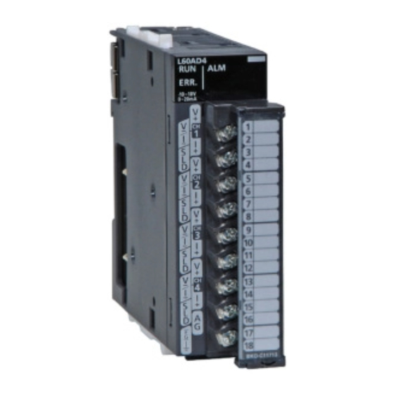
Page 19: Chapter 2 Part Names
CHAPTER 2 PART NAMES CHAPTER 2 PART NAMES The following table shows part names of the A/D converter module. Number Name Description Module joint levers Levers for connecting modules Displays the operating status of the A/D converter module. On: The module is operating normally. RUN LED (green) Flashing: In the offset/gain setting mode Off: The 5V power off or watchdog timer error has occurred. - Page 20 Memo...
-
Page 21: Chapter 3 Specifications
CHAPTER 3 SPECIFICATIONS CHAPTER 3 SPECIFICATIONS This chapter shows the general specifications, performance specifications, function list, list of I/O signals, and list of buffer memory addresses. General Specifications For the general specifications of the A/D converter module, refer to the following. MELSEC-L CPU Module User's Manual (Hardware Design, Maintenance and Inspection) -
Page 22: Performance Specifications
Performance Specifications The following table shows the performance specifications of the A/D converter module. Model Item L60AD4 Number of analog input points 4 points (4 channels) -10 to 10 VDC (input resistance 1M Ω) Voltage Analog input 0 to 20mADC (input resistance 250 Ω) Current Digital output -20480 to 20479... -
Page 23: Number Of Parameter Settings
CHAPTER 3 SPECIFICATIONS 3.2.1 Number of parameter settings Set the initial setting of A/D converter module and the parameter setting of auto refresh setting so that the number of parameters, including these of other intelligent function modules, does not exceed the number of parameters that can be set in the CPU module. -
Page 24: Function List
Function List The following is the function list of the A/D converter module. Item Description Reference Sets whether to enable or disable A/D conversion for each channel. Page 48, A/D conversion enable/disable function Disabling the A/D conversion for unused channels reduces the Section 8.2 conversion cycles. -
Page 25: I/O Signal List
CHAPTER 3 SPECIFICATIONS I/O Signal List The following shows the list of the A/D converter module I/O signals. For the details of I/O signals, refer to the followings. • Details of I/O signals ( Page 95, Appendix 1) Input signal Output signal Device number Signal name... -
Page 26: List Of Buffer Memory Addresses
List of Buffer Memory Addresses The following shows the list of the A/D converter module buffer memory. For details of buffer memory addresses, refer to the following. • Details of buffer memory addresses ( Page 102, Appendix 2) Do not write data to the system area and the area where the data cannot be written from the program in the buffer memory. Writing data to these areas may lead the module to malfunction. - Page 27 CHAPTER 3 SPECIFICATIONS Address Address Default Read/Write Name (decimal) (hexadecimal) ⎯ ⎯ System area CH1 Maximum value CH1 Minimum value CH2 Maximum value CH2 Minimum value CH3 Maximum value CH3 Minimum value CH4 Maximum value CH4 Minimum value ⎯ ⎯ System area 000F Input signal error detection setting...
- Page 28 Address Address Default Read/Write Name (decimal) (hexadecimal) CH1 Process alarm upper upper limit value CH2 Process alarm lower lower limit value CH2 Process alarm lower upper limit value CH2 Process alarm upper lower limit value CH2 Process alarm upper upper limit value CH3 Process alarm lower lower limit value CH3 Process alarm lower upper limit value CH3 Process alarm upper lower limit value...
- Page 29 CHAPTER 3 SPECIFICATIONS Address Address Default Read/Write Name (decimal) (hexadecimal) CH4 Industrial shipment settings offset value (L) CH4 Industrial shipment settings offset value (H) CH4 Industrial shipment settings gain value (L) CH4 Industrial shipment settings gain value (H) CH1 User range settings offset value (L) CH1 User range settings offset value (H) CH1 User range settings gain value (L) CH1 User range settings gain value (H)
- Page 30 (2) Error history (Un\G1800 to Un\G1969) Address Address Default Read/Write Name (decimal) (hexadecimal) 1800 Latest error code address 1801 ⎯ ⎯ System area 1809 1810 Error code First two Last two 1811 digits of the digits of the year year 1812 Month Error time...
- Page 31 CHAPTER 3 SPECIFICATIONS Address Address Default Read/Write Name (decimal) (hexadecimal) 1900 No.10 Same as No. 1 1909 1910 No.11 Same as No. 1 1919 1920 No.12 Same as No. 1 1929 1930 No.13 Same as No. 1 1939 1940 No.14 Same as No.
-
Page 32: Chapter 4 Procedures Before Starting The Operation
CHAPTER 4 PROCEDURES BEFORE STARTING THE OPERATION This chapter describes the procedures before starting the operation. Start Module mounting Page 32, Section 5.1 Mount the A/D converter module in any desired configuration. Wiring Page 38, Section 6.4 Connects external devices to the A/D converter module. Adding a module model Page 39, Section 7.1 Adds the model of the A/D converter module. - Page 33 CHAPTER 4 PROCEDURES BEFORE STARTING THE OPERATION Memo...
-
Page 34: Chapter 5 System Configuration
CHAPTER 5 SYSTEM CONFIGURATION This chapter describes the overall configuration, number of connectable modules, and compatible software version of the A/D converter module. Overall System Configuration The following shows a system configuration example for using the A/D converter module. Display unit (optional) I/O module or intelligent function... - Page 35 CHAPTER 5 SYSTEM CONFIGURATION Memo...
-
Page 36: Chapter 6 Installation And Wiring
CHAPTER 6 INSTALLATION AND WIRING This chapter describes the installation and wiring of the A/D converter module. Installation Environment and Installation Position For precautions for installation environment and installation position, refer to the following. MELSEC-L CPU Module User's Manual (Hardware Design, Maintenance and Inspection) -
Page 37: Terminal Block
CHAPTER 6 INSTALLATION AND WIRING Terminal Block (1) Precautions Tighten the terminal block screws within the following specified torque range. Screw type Tightening torque range Terminal screw (M3 screw) 0.42 to 0.58N • m Terminal block mounting screw (M3.5 screw) 0.66 to 0.89N •... - Page 38 (3) Removal and installation of the terminal block The following shows how to remove and install the terminal block. (a) Removal procedure Open the terminal cover and loosen the terminal block mounting screw. Terminal block mounting screw Using the terminal block fixing holes as a fulcrum, remove the terminal block.
-
Page 39: Wiring
CHAPTER 6 INSTALLATION AND WIRING Wiring (1) Wiring to a terminal block The following shows wirings to a terminal block. (a) For the voltage input V-/I- V-/I- V-/I- V-/I- (b) For the current input V-/I- V-/I- V-/I- V-/I-... -
Page 40: External Wiring
External Wiring The following describes the external wiring. (1) For voltage input Signal source -10 to 10V 500k V-/I- 500k Shield (2) For current input Signal source 0 to 20mA 500k V-/I- 500k Shield For the wire, use the shielded twisted pair cable. This indicates the input resistance of the A/D converter module. -
Page 41: Chapter 7 Various Settings
CHAPTER 7 VARIOUS SETTINGS CHAPTER 7 VARIOUS SETTINGS This chapter describes the setting procedures of the A/D converter module. After writing the contents of new module, switch settings, parameter settings and auto refresh settings into the CPU module, reset the CPU module, switch STOP → RUN → STOP → RUN, or switch ON the power supply, to validate the setting contents. -
Page 42: Switch Setting
Switch Setting Set the operation mode and the input range used in each CH. (1) Setting procedure Set from "Switch Setting" in the project window. Project window [Intelligent Function Module] module name "Switch Setting" Item Description Setting value • 4 to 20mA (default value) •... -
Page 43: Parameter Setting
CHAPTER 7 VARIOUS SETTINGS Parameter Setting Set the parameters of each CH. (1) Setting procedure Set from "Parameter" in the project window. Start "Parameter" from the project window. Project window [Intelligent Function Module] module name "Parameter" Pull-down list type Text box type Double-click the item to change the setting, and input the setting value. - Page 44 Item Setting value Reference A/D conversion enable/disable 0: Enable (default value) Page 48, setting 1: Disable Section 8.2 0: Sampling Processing (default value) 1: Time Average Averaging process specification 2: Count Average 3: Moving Average 20µs: 2 to 1500ms (default value: 0) Average time 80µs, 1ms: 2 to 5000ms (default value: 0) Page 48,...
-
Page 45: Auto Refresh
CHAPTER 7 VARIOUS SETTINGS Auto Refresh This function transfers data in the buffer memory to specified devices. (1) Setting procedure Start "Auto_Refresh" from the project window. Project window [Intelligent Function Module] module name "Auto_Refresh" Click the item to setup, and input the auto refresh target device. -
Page 46: Offset/Gain Setting
Offset/Gain Setting When using the user range setting, configure the offset/gain setting with the following operations. When using factory default settings, the offset/gain is not required. (1) Setting procedure [Tool] [Intelligent Function Module Tool] [Analog Module] [Offset/gain setting] Select the module to configure the offset/gain setting, and click the button. - Page 47 CHAPTER 7 VARIOUS SETTINGS Input the offset value voltage or current in the target channel terminal, and click the button. ↓ Check if "Offset Status" is changed to "Changed", and click the button. ↓ Input the gain value voltage or current in the target channel terminal, and click the button.
- Page 48 Click the button. ↓...
-
Page 49: Chapter 8 Functions
CHAPTER 8 FUNCTIONS CHAPTER 8 FUNCTIONS This chapter describes the details of the functions available in the A/D converter module, and the setting procedures for those functions. For details on I/O signals and buffer memory, refer to the following. • Details of I/O signals ( Page 95, Appendix 1) •... -
Page 50: A/D Conversion Enable/Disable Function
A/D Conversion Enable/Disable Function Sets whether to enable or disable A/D conversion for each channel. By disabling A/D conversion for the channels you are not using, the conversion cycle can be reduced. (1) Setting procedure Set "A/D conversion enable/disable setting" to "0: Enable". Project window [Intelligent Function Module] module name... - Page 51 CHAPTER 8 FUNCTIONS (a) Time average Performs A/D conversion for a set time, averages the total without the maximum and minimum values, and stores the average value to the buffer memory. The processing count within the setting time varies depending on the number of channels used (number of channels for which A/D conversion is enabled).
- Page 52 Because the count average requires a sum of at least two counts, not counting the maximum and minimum values, the set number of times should be set to 4 or more. (c) Moving average Takes the average of digital output values sampled over a set number of sampling time intervals, and stores it to the buffer memory.
- Page 53 CHAPTER 8 FUNCTIONS (b) Averaging processing To select "1: Time" for "Averaging process specification": Set "A/D conversion enable/disable setting" to "0: Enable". Project window [Intelligent Function Module] module name [Parameter] For "Averaging process specification", select "1: Time Average". For "Average time/Average number of times/Move average settings", enter the following: Setting item Conversion speed Setting range...
-
Page 54: Conversion Speed Switch Function
Conversion Speed Switch Function You can select from three conversion speeds: • High speed: 20 µs/channel • Medium speed: 80 µs/channel • Low speed: 1 ms/channel (1) Setting procedure Set "A/D conversion enable/disable setting" to "0: Enable". Project window [Intelligent Function Module] module name [Parameter] For "Conversion speed setting", select the appropriate conversion speed. -
Page 55: Input Signal Error Detection Function
CHAPTER 8 FUNCTIONS Input Signal Error Detection Function Detects any analog input value that is outside the setting range. Analog input value Input signal error detection upper limit value CH1 Analog input value Normal input value Input signal error detection lower limit value Error Time... - Page 56 (3) Detection cycle This function is executed per sampling cycle or averaging process cycle. (4) Clearing the input signal error detection After the analog input value returns within the setting range, turn Error clear request (YF) OFF → ON → OFF. When you clear the input signal error detection, the A/D converter module results in the following state: •...
- Page 57 CHAPTER 8 FUNCTIONS (6) Setting procedure Set "A/D conversion enable/disable setting" to "0: Enable". Project window [Intelligent Function Module] module name [Parameter] Set "Input signal error detection" to "0: Enable". Set a value for "Input signal error detection setting value". Item Setting range Input signal error detection setting...
-
Page 58: Warning Output Function (Process Alarm)
Warning Output Function (Process Alarm) Outputs an alarm when the digital output value enters a preset range. Warning output range Out of warning output range Digital output value Included Warning Warning Upper upper limit value Upper lower limit value Warning cleared Warning cleared CH1 digital output value Lower upper... - Page 59 CHAPTER 8 FUNCTIONS (3) Detection cycle When time average is specified, the function is executed per set time (for averaging). When count average is specified, the function is executed per set count (for averaging). In addition, when sampling processing and moving average processing are specified, the function is executed per sampling time.
- Page 60 (6) Setting procedure Set "A/D conversion enable/disable setting" to "0: Enable". Project window [Intelligent Function Module] module name [Parameter] Set "Process alarm output setting" to "0: Enable". Specify the values for "Process alarm upper upper limit", "Process alarm upper lower limit value", "Process alarm lower upper limit value", and "Process alarm lower lower limit value".
-
Page 61: Scaling Function
CHAPTER 8 FUNCTIONS Scaling Function Performs scale conversion on the digital values that are output. The values are converted in the range between the scaling upper limit value and the scaling lower limit value. The converted values are stored to CH Scaling value (Un\G54 to Un\G57). - Page 62 (3) Setting procedure Set "A/D conversion enable/disable setting" to "0: Enable". Project window [Intelligent Function Module] module name [Parameter] Set "Scaling enable/disable setting" to "0: Enable". Set values for "Scaling upper limit value" and "Scaling lower limit value". Item Setting range Scaling upper limit value -32000 to 32000 Scaling lower limit value...
- Page 63 CHAPTER 8 FUNCTIONS (4) Example of scaling setting 1. When setting the "Scaling upper limit value" to "16000" and the "Scaling lower limit value" to "4000" for a channel with input range of 0V to 5V: The digital output values and scaling values are as follows: Digital output value 20000 Scaling upper limit value 16000...
-
Page 64: Error Log Function
Error Log Function Stores a history of errors and alarms that occurred in the A/D converter module to the buffer memory (Un\G1810 to Un\G1969). A maximum of 16 errors and alarms can be stored. (1) Process of the error log function The error code and the time of error occurrence are stored in the buffer memory address, starting from error history No.1 (start address Un\G1810) and sequentially thereafter. - Page 65 CHAPTER 8 FUNCTIONS 2. When a 17th error occurs: The 17th error is stored in error history No.1, and the value "1810" (start address of error history No.1) gets stored to Latest error code address (Un\G1800). Latest error code address (Un\G1800) Address 1810...
-
Page 66: Module Error Collection Function
8.10 Module Error Collection Function Collects the errors and alarms that occurred in the A/D converter module, into the CPU module. By holding the module errors in a memory that can hold data in the event of power failure, the errors can be held even after power-off or reset. Error history (CPU module) and error log (intelligent function module) are displayed in one screen. -
Page 67: Error Clear Function
CHAPTER 8 FUNCTIONS 8.11 Error Clear Function When an error occurs, you can clear the error from the system monitor. By clicking the button in the system monitor, the latest error code stored in Latest error code (Un\G19) is cleared and the ERR. LED is also turned off. The operation is the same as Error clear request (YF) as well as executing error clear from the display unit. -
Page 68: Saving And Restoring Offset/Gain Values
8.12 Saving and Restoring Offset/Gain Values With the A/D converter module, you can save and restore offset/gain values in the user range setting. In the event that the A/D converter module fails and need to be replaced, you can restore the offset/gain values of the failed A/D converter module onto a replacement A/D converter module. - Page 69 CHAPTER 8 FUNCTIONS (b) To apply the offset/gain values of one module to the other modules in the same system: Here, the offset/gain setting of module No.1 is applied to modules No.2 to No.4. Save the offset/gain values of module No.1. ↓...
- Page 70 (b) Saving and restoring by reading from and writing to the buffer memory In the buffer memory, use Pass data classification setting (Un\G200), CH1 Industrial shipment settings offset value (L)(Un\G202) to CH4 User range settings gain value (H)(Un\G233), and User range write request (YA) to read the offset/gain values from the source A/D converter module, then use the buffer memory again to write to the destination A/D converter module.
- Page 71 CHAPTER 8 FUNCTIONS • To apply the offset/gain values of one module to the other modules: Start Sets values in Pass data classification setting (Un\G200). Turns off, then on, and off again Operating condition setting request (Y9). For the source A/D converter module Records the data stored in Pass data classification setting (Un\G200) and CH1 Industrial shipment settings offset value (L) (Un\G202) to CH4 User...
- Page 72 (3) Range reference tables Below are reference ranges to be used for saving and restoring offset/gain values. (a) Reference table for CH1 Industrial shipment settings offset value (L)(Un\G202) to CH4 Industrial shipment settings gain value (H)(Un\G217) The reference values will vary depending on Pass data classification setting (Un\G200) (voltage or current). Address (decimal) Pass data Reference value...
-
Page 73: Chapter 9 Display Unit
CHAPTER 9 DISPLAY UNIT CHAPTER 9 DISPLAY UNIT This chapter describes the functions of the display unit that can be used with the A/D converter module. For instruction on operating the display unit, or for details on the functions and menu configuration, refer to the following. - Page 74 (2) Screen transitions up to the initial setting change screen The diagram below shows how the screens transition to the initial setting change screen. A/D conversion enable and disable setting screen Standby screen Process alarm lower lower limit screen Averaging process specification screen Input signal error setting screen Function selection screen...
-
Page 75: List Of Setting Value Change Screens
CHAPTER 9 DISPLAY UNIT List of Setting Value Change Screens The following is a list of setting value change screens. (1) Displayed in English: Name Input limits Screen format Setting item Screen display Upper limit Lower limit ⎯ ⎯ A/D conversion enable/disable setting A/D CONVERSION Selection ⎯... - Page 76 (2) A/D CONVERSION Select "ENABLE" or "DISABLE" in the "A/D conversion enable/disable" screen. "A/D conversion enable/disable" screen Use the buttons to select "ENABLE" or "DISABLE", and then confirm with the button. (3) AVE PROCESSING In the "Average processing specification" screen, select whether to perform sampling processing or averaging processing (time average, count average, moving average).
- Page 77 CHAPTER 9 DISPLAY UNIT (4) PROCESS ALARM Select "DISABLE" or "ENABLE" in the "Process alarm setting" screen. "Process alarm setting" screen Use the buttons to select "DISABLE" or "ENABLE", and then confirm with the button. (If you selected "ENABLE", follow the rest of the procedure.) ↓...
- Page 78 (5) INPUT SIG ERR Select "DISABLE" or "ENABLE" in the "Input signal error" screen. "Input signal error" screen Use the buttons to select "DISABLE" or "ENABLE", and then confirm with the button. (If you selected "ENABLE", proceed to step 2.) ↓...
- Page 79 CHAPTER 9 DISPLAY UNIT (6) SCALING Select "DISABLE" or "ENABLE" in the "Scaling setting" screen. "Scaling setting" screen Use the buttons to select "DISABLE" or "ENABLE", and then confirm with the button. (If you selected "ENABLE", follow the rest of the procedure.) ↓...
-
Page 80: Checking And Clearing Errors
Checking and Clearing Errors You can check the errors that occurred in the A/D converter module, from the display unit. In addition, you can also clear an error during its occurrence. (1) Checking the error You can check the error that occurred in the A/D converter module, by specifying Latest error code (Un\G19) from "buffer memory monitor/test". - Page 81 CHAPTER 9 DISPLAY UNIT (2) Clearing errors You can clear an error by eliminating the cause of the error, and turning Error clear request (YF) OFF → ON → OFF from "Device Monitor/Test". Suppose an error occurred in the A/D converter module with start I/O number of X/Y10 to 1F. "CPU monitor/test"...
-
Page 82: Chapter 10 Programming
CHAPTER 10 PROGRAMMING This chapter describes the procedure for programming and the basic program of the A/D converter module. 10.1 Procedure for Programming Create a program to execute A/D conversion, according to the following procedure. Start (1) Initial setting program Performs initial setting by using a program. -
Page 83: When Using The Module In A Standard System Configuration
CHAPTER 10 PROGRAMMING 10.2 When Using the Module in a Standard System Configuration The following shows program examples for the system configuration and usage conditions of the A/D converter module. (1) System configuration The following shows an example of the system configuration when using the module in a standard system configuration. - Page 84 (3) Switch setting Set the input range and the operation mode. Project window [Intelligent Function Module] module name "Switch Setting"...
- Page 85 CHAPTER 10 PROGRAMMING (4) Initial setting description (a) Channel setting Description Item A/D conversion enable/disable Enable Enable Enable Disable setting Sampling Sampling Averaging process specification Count average Moving average processing processing Average time/Average number of 50 times 10 times times/Move average settings Conversion speed setting 20µs Process alarm output setting...
- Page 86 (5) Program example when using the parameter of intelligent function module (a) Parameter setting Set the contents of initial settings in the parameter. Project window [Intelligent Function Module] module name [Parameter] (b) Auto refresh setting Project window [Intelligent Function Module] module name [auto refresh] (c) Writing parameter of intelligent function module...
- Page 87 CHAPTER 10 PROGRAMMING (d) Program example Read digital output values Reads A/D conversion completed flag. Reads CH1 digital output value. Reads CH2 digital output value. Reads CH3 scaling value. Process alarm occurrence status and processing at warning occurrence Process alarm occurrence status and processing at warning occurrence Reads Warning output flag.
- Page 88 (6) Program example when not using the parameter of intelligent function module Initial settings Enables CH1 to CH3 A/D conversion. Sets CH2 time/count/moving average. Sets CH3 time/count/moving average. Sets CH1 to CH3 averaging processing. Sets conversion speed. Sets CH2 warning output. Sets CH2 process alarm lower lower limit value.
-
Page 89: Chapter 11 Troubleshooting
CHAPTER 11 TROUBLESHOOTING CHAPTER 11 TROUBLESHOOTING This chapter describes errors that may occur while the use of the A/D converter module, those troubleshooting. (1) Checking the error codes and the alarm codes Errors and alarms occurred in the A/D converter module can be checked by any of the following methods: •... -
Page 90: Checking By Latest Error Code (Un\G19)
11.2 Checking by Latest Error Code (Un\G19) The following describes how to check the error codes and alarm codes in Latest error code (Un\G19). [Online] [Monitor] [Device/Buffer Memory Batch] 11.3 Checking on the Module Error Collection Function Using the module error collection function stores the errors occurred in the A/D converter module to the CPU module. Once being stored, the errors remain even after power-off or reset of the CPU module. -
Page 91: Error Code List
If the same error occurs again, the possible cause is a failure of the module. A hardware failure occurs in the module. Please consult your local Mitsubishi service center or representative, explaining a detailed description of the problem. Set "0" for Switch 5 in the Switch Setting for I/O and Other than "0"... - Page 92 Error code Description and cause of error Action (decimal) A value outside 2 to 5000 is set to Time Average of CH Correct the value within the range of 2 to 5000. Average time/Average number of times/Move average settings Also, set a value greater than or equal to the value (Un\G1 to Un\G4).
-
Page 93: Alarm Code List
Reset the CPU module, and check if the RUN LED turns on. If the RUN LED remains off, the module may be failed. Please Is there any watchdog timer error? consult your local Mitsubishi service center or representative, explaining a detailed description of the problem. Is the module connected properly? - Page 94 (2) When the ERR. LED turns on or flashes (a) When turning on Check item Action Check Latest error code (Un\G19), and take actions in the error code list. Does any error occur? • Error Code List ( Page 89, Section 11.4) (b) When flashing Check item Action...
- Page 95 If digital output value cannot be read even after taking the above actions, module may be failed. Please consult your local Mitsubishi service center or representative, explaining a detailed description of the problem. (5) When an A/D conversion completed flag does not turn on in the normal mode...
-
Page 96: Checking The Status Of The A/D Converter Module By The System Monitor
11.7 Checking the Status of the A/D Converter Module by the System Monitor To check the LED status or the setting status of the intelligent function module switch setting, select the H/W information of the A/D converter module on the system monitor of GX Works2. (1) Hardware LED information LED status is displayed. -
Page 97: Appendices
APPENDICES APPENDICES Appendix 1 Details of I/O Signals The following describes the details of the A/D converter module I/O signals assigned to the CPU module. The I/O number described in Appendix 1 shows the case that the start I/O number of the A/D converter module is set to "0". - Page 98 (3) Operating condition setting completed flag (X9) When changing the following settings, use Operating condition setting completed flag (X9) as an interlock condition to turn Operating condition setting request (Y9) OFF → ON → OFF. • A/D conversion enable/disable setting (Un\G0) •...
- Page 99 APPENDICES (4) Offset/gain setting mode flag (XA) (a) Offset/gain setting mode When registering the value, which was adjusted with the offset/gain setting, to the module, use Offset/gain setting mode flag (XA) as an interlock condition to turn User range write request (YA) OFF → ON → OFF. For the offset/gain setting, refer to the following.
- Page 100 (6) Input signal error detection signal (XC) • Input signal error detection signal (XC) turns to ON when an analog input value exceeds the range set with Input signal error detection setting value (Un\G142 to Un\G145) in any channel which has been A/D conversion-enabled, after validating the input signal error detection.
- Page 101 APPENDICES (8) A/D conversion completed flag (XE) A/D conversion completed flag (XE) turns ON when all A/D conversion-enabled channels are converted. (9) Error occurrence flag (XF) Error occurrence flag (XF) turns ON when an error occurs. Controlled by the A/D converter module Controlled by the program Latest error code (Un\G19) Error...
-
Page 102: Appendix 1.2 Output Signal
Appendix 1.2 Output signal (1) Operating condition setting request (Y9) To validate the following settings, turn Operating condition setting request (Y9) OFF→ ON → OFF. • A/D conversion enable/disable setting (Un\G0) • CH Average time/Average number of times/Move average settings (Un\G1 to Un\G4) •... - Page 103 APPENDICES (5) Error clear request (YF) To clear Error occurrence flag (XF), Input signal error detection signal (XC), and Latest error code (Un\G19), turn Error clear request (YF) OFF → ON → OFF. For the timing of turning the signal OFF → ON → OFF, refer to the following. •...
-
Page 104: Appendix 2 Details Of Buffer Memory Addresses
Appendix 2 Details of Buffer Memory Addresses The following describes the details of buffer memory addresses of the A/D converter module. (1) A/D conversion enable/disable setting (Un\G0) Set if the A/D conversion is enabled or disabled for each channel. b15 b14 b13 b12 b11 b10 b9 b8 b7 b6 b5 Data for b4 to b15 are fixed to "0". - Page 105 APPENDICES (3) Averaging process specification (used to replace Q64AD) (Un\G9) Write the setting for averaging processing when using the sequence program for initial setting of the Q64AD. b15 b14 b13 b12 b11 b10 b9 b8 b7 b6 b5 0 CH4 CH3 CH2 CH1 0 Averaging processing channel specification Time/number of times specification 1: Averaging processing...
- Page 106 (5) CH Digital output value (Un\G11 to Un\G14) The A/D-converted digital output value is stored as a signed 16-bit binary value. b15 b14 b13 b12 b11 b10 b9 b8 b7 b6 b5 Data section Sign bit 1: Negative 2: Positive (a) Updating cycle When performing the average processing, the value is updated in each specified averaging processing cycle.
- Page 107 APPENDICES (8) Offset/gain setting mode Offset specification (Un\G22), Offset/gain setting mode Gain specification (Un\G23) Specify the channel to perform the offset/gain setting adjustment. Offset/gain setting mode Offset specification (Un\G22): channel to adjust the offset Offset/gain setting mode Gain specification (Un\G23): channel to adjust the gain b15 b14 b13 b12 b11 b10 b9 b8 b7 b6 b5 Offset/gain setting mode Offset specification (Un\G22) Offset/gain setting mode Gain specification (Un\G23)
- Page 108 (10)Conversion speed setting (Un\G26) Set the conversion speed for all channels. When the value of 3 to FFFF is set, an error occurs and the operation is performed in the previous setting. Setting range Conversion speed Setting value 20μs 80μs (a) Enabling the setting Turn OFF →...
- Page 109 APPENDICES (13)Process alarm output setting (Un\G48) Set whether the alarm output of process alarm is enabled or disabled for each channel. b15 b14 b13 b12 b11 b10 b9 b8 b7 b6 b5 Data for b4 to b15 are fixed to "0". 0: Enabled 1: Disabled (a) Enabling the setting...
- Page 110 (15)Warning output flag (Process alarm) (Un\G50) Alarms can be checked if the alarm is the upper limit alarm or lower limit alarm, for each channel. b15 b14 b13 b12 b11 b10 b9 b8 b7 b6 b5 CH4 CH4 Data for b4 to b15 are fixed to "0". 0: Normal 1: Alarm on (a) Warning output flag (Process alarm) (Un\G50) status...
- Page 111 APPENDICES (17)CH Scaling value (Un\G54 to Un\G57) The digital output value which is scale-converted using the CH1 Scaling lower limit value (Un\G62) to CH4 Scaling upper limit value (Un\G69) is stored as signed 16-bit binary. b15 b14 b13 b12 b11 b10 b9 b8 b7 b6 b5 Data section Sign bit 1: Negative...
- Page 112 (19)CH Process alarm lower lower limit value (Un\G86, Un\G90, Un\G94, Un\G98), Process alarm lower upper limit value (Un\G87, Un\G91, Un\G95, Un\G99), Process alarm upper lower limit value (Un\G88, Un\G92, Un\G96, Un\G100), Process alarm upper upper limit value (Un\G89, Un\G93, Un\G97, Un\G101) Set the digital output value range for each channel.
- Page 113 APPENDICES (20)CH Input signal error detection setting value (Un\G142 to Un\G145) Set the setting value to detect an input analog value error for each channel. For details on input signal error detection function, refer to the following. • Input Signal Error Detection Function ( Page 53, Section 8.6) (a) Setting procedure •...
- Page 114 (21)Mode switching setting (Un\G158, Un\G159) Set the setting value for the mode to be switched to. When the mode is switched, this area is cleared to zero and Operating condition setting completed flag (X9) is turned to OFF. After checking that the operating condition setting complete/completion flag is OFF, turn Operating condition setting request (Y9) to OFF.
- Page 115 APPENDICES (23)CH1 Industrial shipment settings offset value (L) (Un\G202) to CH4 User range settings gain value (H) (Un\G233) This is the area for restoring the offset/gain setting value in user range setting. The data to be used when restoring the offset/gain setting value in user range setting is stored. The data is stored when;...
-
Page 116: Appendix 3 I/O Conversion Characteristic Of A/D Conversion
Appendix 3 I/O Conversion Characteristic of A/D Conversion I/O conversion characteristic of A/D conversion means the slope of the line connected between the offset value and gain value when converting the analog signal (voltage or current input) from outside of programmable controller to digital value. - Page 117 APPENDICES (3) Voltage input characteristic The following graph shows the voltage input characteristic. Practical analog input range 20479 20000 APPEN -480 -20000 -20480 Analog input voltage (V) Input range setting Offset value Gain value Resolution Digital output value * 1 to 5V 200μV 0 to 20000 0 to 5V...
- Page 118 (4) Current input characteristic The following graph shows the current input characteristic. Practical analog input range 20479 20000 -480 -20000 -20480 Analog input current (mA) Input range setting Offset value Gain value Resolution Digital output value * 4 to 20mA 20mA 800nA 0 to 20000...
-
Page 119: Appendix 4 A/D Conversion Accuracy
APPENDICES Appendix 4 A/D Conversion Accuracy The A/D conversion accuracy is the accuracy for the maximum value of digital output value. Even when changing the offset/gain setting and input range to change the input characteristics, the accuracy does not change and is kept within the range of described performance specifications. The following graph shows the fluctuation range of accuracy when the range of -10 to 10V is selected. -
Page 120: Appendix 5 Dedicated Instruction
Appendix 5 Dedicated Instruction This chapter describes the dedicated instructions that can be used in A/D converter module. Appendix 5.1 Instruction list The following shows the dedicated instructions that can be used in the A/D converter module. Instruction Description • The operation mode is changed to the offset/gain setting mode. G(P).OFFGAN •... -
Page 121: Appendix 5.2 G(P).Offgan
APPENDICES Appendix 5.2 G(P).OFFGAN Command G.OFFGAN G.OFFGAN Command APPEN GP.OFFGAN GP.OFFGAN Internal device Setting Constant R, ZR U \G Others data K, H, $ Word Word ⎯ ⎯ (1) Setting data Device Description Setting range Data type 0 to FE Start I/O number of module BIN 16 bits Mode change... - Page 122 (4) Program example The following shows the program of the A/D converter module, installed in I/O number X/Y10 to X/Y1F, with the following conditions: • turning ON M10 switches the operation mode to the offset/gain setting mode, and • turning OFF M10 restores the operation mode to the normal mode. Switches to the offset/gain setting mode.
-
Page 123: Appendix 5.3 G(P).Ogload
APPENDICES Appendix 5.3 G(P).OGLOAD Command G.OGLOAD G.OGLOAD Command GP.OGLOAD APPEN GP.OGLOAD Internal device Setting Constant R, ZR U \G Others data K, H, $ Word Word ⎯ ⎯ ⎯ (1) Setting data Device Description Setting range Data type 0 to FE Start I/O number of module BIN 16 bits Within the range of... - Page 124 (2) Control data Device Item Setting data Setting range Set by System area ⎯ ⎯ ⎯ The status on instruction completion is stored. Completion status : normal completion ⎯ System Other than 0: error completion (error code) Specify the type of offset/gain setting value to read out.
- Page 125 APPENDICES Device Item Setting data Setting range Set by CH3 User range settings gain value (L) ⎯ ⎯ System CH3 User range settings gain value (H) ⎯ ⎯ System CH4 User range settings offset value (L) ⎯ ⎯ System CH4 User range settings offset value (H) ⎯...
- Page 126 (5) Program example The following shows the program to read out the offset/gain setting value of the A/D converter module, installed in I/O number X/Y10 to X/Y1F, by turning ON M11. Sets a control data. Specifies voltage. Reads a offset/gain setting value. Dedicated instruction (GP.OGLOAD) Processing when an instruction execution is failed...
-
Page 127: Appendix 5.4 G(P).Ogstor
APPENDICES Appendix 5.4 G(P).OGSTOR Command G.OGSTOR G.OGSTOR Command GP.OGSTOR APPEN GP.OGSTOR Internal device Setting Constant R, ZR U \G Others data K, H, $ Word Word ⎯ ⎯ ⎯ (1) Setting data Device Description Setting range Data type 0 to FE Start I/O number of module BIN 16 bits Within the range of... - Page 128 (2) Control data Device Item Setting data Setting range Set by ⎯ ⎯ ⎯ System area The status on instruction completion is stored. ⎯ Completion status : normal completion System Other than 0: error completion (error code) The value which is set for Pass data classification setting +2 by G(P).OGLOAD instruction is stored.
- Page 129 APPENDICES Device Item Setting data Setting range Set by ⎯ ⎯ CH3 User range settings offset value (H) System ⎯ ⎯ CH3 User range settings gain value (L) System ⎯ ⎯ CH3 User range settings gain value (H) System ⎯ ⎯...
- Page 130 (5) Program example The following shows the programs to write the offset/gain setting value to A/D converter module, installed in I/O number X/Y10 to X/Y1F, by turning OFF M11. Sets a control data. Restores a offset/gain setting value. Dedicated instruction (GP.OGSTOR) Processing when an instruction execution is failed...
-
Page 131: Appendix 6 Checking Serial Number And Function Version
APPENDICES Appendix 6 Checking Serial Number and Function Version For details on how to check the serial number and function version, refer to the following. MELSEC-L CPU Module User's Manual (Hardware Design, Maintenance and Inspection) Appendix 7 Differences with Q Series The following describes the differences between L series and Q series, and the precautions for configuring the L-series APPEN system using the Q-series program. -
Page 132: Appendix 7.1 Precautions For Applying Q Series Sequence Program
Appendix 7.1 Precautions for Applying Q Series Sequence Program The initial setting program of a Q-series A/D converter module is applicable to the program of the L60AD4 for the input signals and the buffer memory assignment of the L60AD4 are compatible between the L60AD4 and Q64AD. The resolution is also applicable with the use of the module scaling function. - Page 133 APPENDICES (2) Resolution Since the module has 1/20000 resolution, the sequence program can be applied from Q-series A/D converter modules just by using the scaling function. Note that it is the prior condition of the sequence program, applied from a channel isolated A/D converter module (Q68AD-G or Q66AD-DG), does not have the scaling function program.
-
Page 134: Appendix 8 When Using Gx Developer Or Gx Configurator-Ad
Appendix 8 When Using GX Developer or GX Configurator- Appendix 8 describes the operating procedure when using GX Developer and GX Configurator-AD. (1) Compatible software version For compatible software version, refer to the following. MELSEC-L CPU Module User's Manual (Hardware Design, Maintenance and Inspection) Appendix 8.1 Operation of GX Developer Configure the setting on the following screen when using GX Developer. - Page 135 APPENDICES (2) Intelligent function module switch setting Configure the setting from "Switch setting" in "PLC parameter". Parameter [PLC parameter] [I/O assignment] Click the button. Select "HEX.". APPEN Item Setting item Analog input range Input range setting 4 to 20mA Input range setting 0 to 20mA (CH1 to CH4) 1 to 5V...
- Page 136 (3) Offset/gain setting When using the user range setting, configure the offset/gain setting in the following procedure. When using the factory default setting, the offset/gain setting is not necessary. Start Switches to the Offset/gain setting mode.* Checks that the module is in Offset/gain setting mode and the RUN LED is flashing.
- Page 137 APPENDICES ● Configure the offset/gain setting in accordance with the actual use situation. ● Offset and gain values are recorded in the flash memory in the A/D converter module by turning OFF → ON → OFF User range write request (YA). Once recorded, the values are not deleted even after turning the power off. When the values are written 26 times in succession, an error occurs and the error code is stored in Latest error code (Un\G19) to prevent an improper write to flash memory.
- Page 138 (b) Switching the mode by the dedicated instruction (G(P).OFFGAN) This program performs the followings: • first, switches the mode to the offset/gain setting mode by the dedicated instruction (G(P).OFFGAN), • second, switches the channels for which the offset/gain settings is configured, •...
- Page 139 APPENDICES (c) Switching the mode by Mode switching setting (U3\G158, U3\G159) and Operating condition setting request (Y39) Switches to the offset/gain setting mode. Sets 4144 to Mode switching setting 1 (U3\G158). Sets 0964 to Mode switching setting 2 (U3\G159). Turns on Operating condition setting request (Y39).
-
Page 140: Appendix 8.2 Operation Of Gx Configurator-Ad
Appendix 8.2 Operation of GX Configurator-AD When setting the A/D converter module parameter using GX Configurator-AD, the display method such as a setting screen differs from that of GX Works2. This section describes the screen display method of GX Configurator-AD. The setting contents are the same as GX Works2. - Page 141 APPENDICES <<FB Support Parameter>> tab - FB conversion [Online] - [Monitor/Test] Select monitor/test module screen FB conversion screen APPEN Select a module to be monitored/tested. Monitor/Test screen...
-
Page 142: Appendix 9 External Dimensions
Appendix 9 External Dimensions The following shows the external dimensions of A/D converter module. (1) L60AD4 DIN rail center 28.5 (Unit: mm) -
Page 143: Index
INDEX ......62 Error log function ....99 Error occurrence flag (XF) . - Page 144 ....70 Range reference tables ..66 Saving and restoring offset/gain values ..108 Scaling enable/disable setting (Un\G53) .
-
Page 145: Instruction Index
INSTRUCTION INDEX ......119 G(P).OFFGAN ......121 G(P).OGLOAD . -
Page 146: Revisions
This manual confers no industrial property rights or any rights of any other kind, nor does it confer any patent licenses. Mitsubishi Electric Corporation cannot be held responsible for any problems involving industrial property rights which may occur as a result of using the contents noted in this manual. -
Page 147: Warranty
6. Failure caused by reasons unpredictable by scientific technology standards at time of shipment from Mitsubishi. 7. Any other failure found not to be the responsibility of Mitsubishi or that admitted not to be so by the user. 2. Onerous repair term after discontinuation of production (1) Mitsubishi shall accept onerous product repairs for seven (7) years after production of the product is discontinued. - Page 148 Microsoft, Windows, Windows NT, and Windows Vista are registered trademarks of Microsoft Corporation in the United States and other countries. Pentium is a trademark of Intel Corporation in the United States and other countries. Ethernet is a trademark of Xerox Corporation. All other company names and product names used in this manual are trademarks or registered trademarks of their respective companies.
Need help?
Do you have a question about the MELSEC-L Series and is the answer not in the manual?
Questions and answers