Table of Contents
Advertisement
Quick Links
Advertisement
Table of Contents

Related Manuals for Flow vision FC100 - CA


Summary of Contents for Flow vision FC100 - CA
- Page 1 Flow Meter | FC100 - CA USER MANUAL M_FC100-CA_1121_e...
- Page 2 Flow Meter | FC100-CA Important: Please follow these instructions carefully. Failure to comply, or misuse of this equipment, could result in serious damage both to the equipment itself and to the installation. FlowVision is unable to accept responsibility for customer or third party liability, warranty claims or damage caused by incorrect installation or improper handling resulting form non-observance of these instructions.
-
Page 3: Table Of Contents
FC100-CA | Flow Meter TABLE OF CONTENTS Table of Contents 1 Description . . . . . . . . . . . . . . . . . . . . . . . . . . . . . . . . . . . . . . . . . . . . . . . . . . . . . 6 Measuring procedure. - Page 4 Flow Meter | FC100-CA TABLE OF CONTENTS 3 Operating system . . . . . . . . . . . . . . . . . . . . . . . . . . . . . . . . . . . . . . . . . . . . . . . .34 4 Operation and main menu .
- Page 5 FC100-CA | Flow Meter TABLE OF CONTENTS 7 Technical data . . . . . . . . . . . . . . . . . . . . . . . . . . . . . . . . . . . . . . . . . . . . . . . . . . 62 Ambient conditions.
-
Page 6: Description
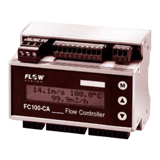
Flow Meter | FC100-CA DESCRIPTION 1 Description Flow Meter FC100-CA is suitable for compressed-air and other gas flow measurements under various pressure conditions. It operates on the calorimetric principle and is to be used together with monitoring heads CSx-... These quantities are made available to the user as analogue electrical signals, physically isolated, as current or voltage output and may be monitored by means of a limit monitor. -
Page 7: Physical Principles Of Gas Measurement
FC100-CA | Flow Meter DESCRIPTION Major benefits of this method are: • Fast response, particularly in the event of a sudden complete flow stoppage. • Medium temperature measurement, providing optimal temperature compensation. • Increased safety because the sensor cannot be overheated during flow standstill. The flow velocity is determined by mass flow. -
Page 8: Measurements In Compressed-Air Systems
Flow Meter | FC100-CA DESCRIPTION 1 . 1 .4 Measurements in compressed-air systems The easy-to-fit modular insertion system allows the FC100-CA with insertion head CSP-… to be inserted in 6 different sensor adapters for diameters 1/2“, 3/4“, 1“, 1 1/4“, 1 1/2“ and 2“. This enables to systematically monitor the entire compressed-air system for leakages by providing the appropriate number of sensor adapters and only a few measuring systems. -
Page 9: System Description
FC100-CA | Flow Meter DESCRIPTION 1 .2 System description The system comprises the following hardware functional modules: 1 Input voltage: DC supply (terminal XV) 2 User interfaces: 2.1 signal outputs, 2-way or 4-way signal outputs (terminal XAH) 2.2 analogue outputs (terminal XAO) 2.3 RS232 interface (terminal XSE) 2.4 external totalizer reset (terminal XRE) 3 Keyboard and display:... -
Page 10: User Interfaces
Flow Meter | FC100-CA DESCRIPTION The analogue outputs and the signal outputs are galvanically isolatated from the other electronics . The two analogue output channels are not galvanically isolated from each other. There is no electrical isolation between power supply, controller system, sensor interface, monitoring head and RS232 interface. - Page 11 FC100-CA | Flow Meter DESCRIPTION Power supply: DC 10 … 40 V Internal switched mode power supply without galvanic isolation of the primary and secondary side. The secondary side is short-circuit proof. There is a fuse on the primary side which can only be replaced by FlowVision. Noise emission is limited by appropriate circuit design and filters .
-
Page 12: Installation
Flow Meter | FC100-CA INSTALLATION 2 Installation 2 . 1 Installation of calorimetric monitoring heads These are general directions for the application of calorimetric measuring heads which from application to application should be reviewed by the user in accordance with individual requirements. 2 . -
Page 13: Mechanical Installation
FC100-CA | Flow Meter INSTALLATION 2 . 1 .2 Mechanical installation 2 . 1 .2 . 1 Thread-mounted monitoring head CST-11 Application: general industry and installation Medium: gases Styles: G1/2A Materials of the area exposed to medium: stainless steel 1.4571 /AISI 316 Ti (standard) nickel-based alloy (Hastelloy C4 2.4610) If installed in fittings or T pieces with appropriate internal thread the max. -
Page 14: Insertion Head Csp For Sensor Adapter Tp
Flow Meter | FC100-CA INSTALLATION 2 . 1 .2 .2 Insertion head CSP for sensor adapter TP- … or ball valve BV- … Application: general industry and installation Style: insertion-type for sensor adapter TP-... and ball valve BV-… Installation: sensor adapter TP-.. -
Page 15: Sensor Adapter Tp
FC100-CA | Flow Meter INSTALLATION 2 . 1 .2 .3 Sensor adapter TP- … The sensor adapter TP- … is available in 6 pipe diameters from 1/2“ to 2“. Material of the area exposed to medium: - brass (not TP-03 …) / gunmetall (only TP-03 …) or - stainless steel 1.4571/AISI 316 Ti retention pin Type... -
Page 16: Ball Valve Bv
Flow Meter | FC100-CA INSTALLATION 2 . 1 .2 .4 Ball valve BV- … The ball valve is available in 4 pipe diameters from 1“ to 2“. The ball valve ensures the sensors are fully immersed in the medium. The monitoring head may also be replaced in pressurised pipe systems on duty. -
Page 17: Push-In Monitoring Head Csf-11Am1/Csf-11Am2
FC100-CA | Flow Meter INSTALLATION 2 . 1 .2 .5 Push-in monitoring head CSF-11AM1/CSF-11AM2 Application: general industry and installation recommend for inside pipe diameter >60 mm Style: push-in monitoring head Material of the area exposed to medium: stainless steel 1.4571/AISI 316 Ti nickel-based alloy (Hastelloy C4 2.4610) SW20 circular connector... -
Page 18: Mounting Instructions For Monitoring Head Cst
Flow Meter | FC100-CA INSTALLATION 2 . 1 .3 Mounting instructions for monitoring head CST Caution! The two sensors (M) should be screwed into the pipe far enough to ensure that they are aligned side by side directly across the direction of flow. The sensors are correctly positioned when the wrench flats (S) are aligned parallel to the pipe. -
Page 19: Mounting Instructions For Monitoring Head Csp With Sensor Adapter Tp Or Ball Valve Bv
FC100-CA | Flow Meter INSTALLATION 2 . 1 .4 Mounting instructions for monitoring head CSP with sensor adapter TP or ball valve BV The arrow on the housing of the sensor adapter/ball valve must point in direction of flow. Use hemp, teflon tape or thread sealing glue for sealing pipe connection threads. - Page 20 Flow Meter | FC100-CA INSTALLATION Fit monitoring head with locking set (see fig. 12): • Fix first link of chain (1) into the clip (3). • Put chain catch (2) into link and fasten with the tight chain. Caution! Check locking system with regard to strength! The locking chain must be mounted as tightly as possible .
-
Page 21: Standard Velocity Profiles
FC100-CA | Flow Meter INSTALLATION 2 . 1 .5 . 1 Standard velocity profiles: (for pipe radius = 1 and for velocity averaged via total pipe cross section = 1) -0.75 -0.5 -0.25 0.25 0.75 r - pipe radius v - velocity Velocity range at X = 1/8 dia. -
Page 22: Point Of Installation And Steadying Zones
Flow Meter | FC100-CA INSTALLATION 2 . 1 .6 Point of installation and steadying zones The mounting attitude is unimportant. It is generally sufficient to have a distance of 10 pipe dia meters (D) before the monitoring head without any bends and changes in pipe diameter if the velocity profile is only slightly disturbed. -
Page 23: Condensate Deposits
FC100-CA | Flow Meter INSTALLATION 2 . 1 .7 Condensate deposits Oil or water deposits on the sensors may falsify the measuring results. Such deposits must be expec- ted, for example, when high flow velocities of compressed air are concerned and there is no drying provided. -
Page 24: Installation Of Electronic Control Unit Fc100-Ca
Flow Meter | FC100-CA INSTALLATION 2 .2 Installation of electronic control unit FC100-CA 2 .2 . 1 Mechanical installation 2 .2 . 1 . 1 Rail-mounted version FC100-CA-U1 . . . (see fig. 15) • The electronic housing is mounted on a symmetric (35mm) rail to DIN EN 60715 TH 35 (formerly EN 50022). -
Page 25: Surface Mounted Version Fc100-Ca-Fh-U1
FC100-CA | Flow Meter INSTALLATION 2 .2 . 1 .2 Surface mounted version FC100-CA-FH-U1 . . . (see fig. 16) • Remove the cover of the housing. • Install the housing in place using the 4 screws M4. • Replace the cover and tighten the retaining screws. FC100-CA-FH (surface mounted version) FC100-CA Flow Controller... -
Page 26: Electrical Connection
Flow Meter | FC100-CA INSTALLATION 2 .2 .2 Electrical connection Valid for all plug-in screw terminal strips (XV, XSK, XRE, XSE, XAO, XAH): Cable size: 0.14 mm to 1.5 mm , single or finely stranded conductor XV – Power supply Connection: 3 pole plug-in screw terminal strip Pin No. - Page 27 FC100-CA | Flow Meter INSTALLATION XAO - Analogue outputs (option: V1, V2, C1) Connection: 8 pole plug-in screw terminal strip Pin No. Signal name Function none ANAO1 analogue output 1 - flow ANA1GND reference potential for analogue output 1 SGNDA1 shield connection for analogue output 1 (ungrounded) * SGNDA2 shield connection for analogue output 2 (ungrounded) *...
- Page 28 Flow Meter | FC100-CA INSTALLATION XAH - Limit switch signal outputs - transistor outputs NPN, freely connectable as emitter (-) and collector (+) have been led out separately . Connection: 8 pole plug-in screw terminal strip Pin No. Signal name Function /ERROR E summarized error indication - emitter terminal...
-
Page 29: Circuit Diagram Fc100-Ca (Relay Outputs)
FC100-CA | Flow Meter INSTALLATION 2 .2 .2 . 1 Circuit diagram FC100-CA (relay outputs) 1 2 3 9 10 FC100-CA Flow Cont ro lle r NC: not connected SGNDA1 ungrounded SGNDA2 Apply shield on one side only. analogue outputs ** signal outputs C1, V1, V2 fig. -
Page 30: Circuit Diagram Fc100-Ca (Transistor Outputs (Npn))
Flow Meter | FC100-CA INSTALLATION 2 .2 .2 .2 Circuit diagram FC100-CA (transistor outputs (NPN)) 1 2 3 9 10 FC100-CA Flow Cont ro lle r E/- emitter terminal C/+ collector terminal NC: not connected SGNDA1 ungrounded SGNDA2 Apply shield on one side only. analogue outputs ** signal outputs C1, V1, V 2... -
Page 31: Electrical Connection - Pulse Output (Version Fc100-Ca-U1T4
FC100-CA | Flow Meter INSTALLATION 2 .2 .2 .3 Electrical connection - pulse output (version FC100-CA-U1T4…) The quantity-dependent pulse may be selected in the menu item “USER OUTPUTS” (see chapter 5.9). A square pulse signal is available for driving a counter of a primary control at the plug XAH / BUSY E/- and /BUSY C/+ (pins 3 and 4) (see fig. - Page 32 Flow Meter | FC100-CA INSTALLATION Electromechanical pulse counter (see fig. 21) The FC100-CA driver output comprises an integral safety circuit which when isolating the counter operating coil will limit overvoltages caused by inductance. The counter should be able to process a counting frequency of ≥10 Hz as the pulse length is 50 ms (±1%) continuously.
-
Page 33: Electrical Connection - Totalizer Reset
FC100-CA | Flow Meter INSTALLATION 2 .2 .2 .4 Electrical connection - totalizer reset The FC100-CA has an external totalizer reset. The control signal is connected to plug XRE. The totalizer reset is edge controlled – it is performed when the signal changes from low to high level. There are two possible operating modes (see fig. -
Page 34: Operating System
Flow Meter | FC100-CA OPERATING SYSTEM 3 Operating system Clear menu-driven control, via keyboard and display, enables easy definition of parameters and configuration. This provides high system flexibility, making the FC100-CA the optimum solution for a wide variety of measuring, monitoring and display tasks. When programming the FC100-CA the user is guided by plaintext in the display through menus in which he may enter or select the required functions. - Page 35 FC100-CA | Flow Meter OPERATING SYSTEM Menu paging The next menu option is selected by pressing M MODE (forward paging) . Calling a menu option Simultaneously pressing ▲ UP and ▼ DOWN = ▲ + ▼ calls the selected menu option or causes skipping to the selected submenu.
-
Page 36: Operation And Main Menu
Flow Meter | FC100-CA CONFIGURATION 4 Operation and main menu 4 . 1 Switch-on performance Upon power application POWER-ON TEST will be shown on the display for approx. 2 sec., with the software version number being indicated in the second line. During this period, the integral controller will conduct test routines (see chapter 6.1, Test and diagnosis). -
Page 37: Measuring Operation
FC100-CA | Flow Meter OPERATION AND MAIN MENU 4 .3 Measuring Operation The structure of the menu is shown below. All menu items are described on the following pages. Main menu power on HEATING UP REST-TIME = 26 12,5 m/s 26,0 °C 86,7 m 12,5 m/s... -
Page 38: Peak Values
Flow Meter | FC100-CA OPERATION AND MAIN MENU 4 .3 . 1 Peak values The FC100-CA comprises six specific measured-values memories which may be retrieved in submenu PEAK-VALUES. They store the lowest and highest value of flow velocity, medium temperature and volume flow. After switch-on or NOT-BUSY indication, the minimum and maximum values are deleted and will be continuously updated (non-return pointer principle). - Page 39 FC100-CA | Flow Meter OPERATION AND MAIN MENU Submenu PEAK-VALUES submenu PEAK-VALUES ▲ + ▼ delete all FLOW VELOCITY: MAX values MAX=18,7 m/s ▲ + ▼ delete all FLOW VELOCITY: MIN values MIN=12,5 m/s ▲ + ▼ TEMPERATURE delete all MAX values MAX=105,4 °C ▲ + ▼...
-
Page 40: Limit Switches
Flow Meter | FC100-CA OPERATION AND MAIN MENU 4 .3 .2 Limit switches The next menu item shows the limit switches which are assigned to the physical quantity/quantities. F means the limit switch (LS) is assigned to flow velocity, T means the limit switch is assigned to medium temperature. -
Page 41: Low Flow Suppression And Zero Alignment
FC100-CA | Flow Meter OPERATION AND MAIN MENU 4 .3 .5 Low flow suppression and zero alignment Low flow suppression The low flow suppression serves to suppress small flow quantities and to detect leakages. The low flow suppression option ranging from 1 to 10 % of the measuring range final value can be used to eliminate false measurements as may arise upon (small) reverse flow quantities, for example. -
Page 42: Last Error
Flow Meter | FC100-CA OPERATION AND MAIN MENU submenu ZERO SUPP. 12.5 m/s -13.5 °C MIN.FLOW = 01% back to MAIN MENU MIN.FLOW = 00% ZERO-PT. ALIGNM.? →no M→yes ▲ ▼ ▲ or ▼ back to MAIN MENU ALIGNMENT READY! PUSH M alignment plausible ALIGNMENT OK! ALIGNMENT ERROR! -
Page 43: Configuration
FC100-CA | Flow Meter CONFIGURATION 5 Configuration The CONFIGURATION submenu serves to adjust the FC100-CA to its application. During system configuration, measuring operations are not possible (see appendix 1). submenu CONFIGURATION ▲ + ▼ submenu LANGUAGE SELECT CONFIGURATION LANGUAGE SELECT ▲ + ▼ submenu SENSOR SELECT CONFIGURATION SENSOR SELECT ▲ + ▼... -
Page 44: Language Select
Flow Meter | FC100-CA CONFIGURATION 5 . 1 Language select submenu LANGUAGE SELECT LANGUAGE SELECT ENGLISH ▲ or ▼ back to CONFIGURATION menu LANGUAGE SELECT GERMAN ▲ or ▼ back to CONFIGURATION menu LANGUAGE SELECT FRENCH ▲ or ▼ back to CONFIGURATION menu fig. -
Page 45: Sensor Select
FC100-CA | Flow Meter CONFIGURATION 5 .2 Sensor select submenu SENSOR SELECT SENSOR SELECT SENSOR SELECT SENSOR SELECT SENSOR SELECT SENSOR SELECT CST11AM1 CSP11AM1BV CSP11AM1 CSF11AM1 S-No. 000 SENSOR CODE SENSOR CODE SENSOR CODE SENSOR CODE SENSOR CODE C 555 C 555 C 555 C 555... -
Page 46: Pipe Size
Flow Meter | FC100-CA CONFIGURATION The SENSOR SELECT menu allows the selection of the monitoring head types suitable for com- pressed air applications, that can be used with the FC100-CA. • TYPE CST-11AM1 thread-mounted head • TYPE CSP-11AM1BV insertion head with ball valve BV-… •... -
Page 47: Gas Selection
FC100-CA | Flow Meter CONFIGURATION 5 .4 Gas selection submenu GAS SELECT GAS SELECT GAS SELECT GAS SELECT NITROGEN OXYGEN GAS SELECT GAS SELECT GAS SELECT GAS SELECT ARGON CARBON DIOXIDE METHANE HYDROGEN back to CONFIGURATION fig. 34 menu This menu option allows the selection of the following gases: •... -
Page 48: Pressure Range
Flow Meter | FC100-CA CONFIGURATION 5 .5 Pressure range 5 .5 Pressure range submenu xxx.xx bar PRESS . RANGE xxxx.x PSI back to CONFIGURATION menu fig. 35 Pressure indication serves to correct the measured value and to convert standard volume flow to Pressure indication serves to correct the measured value and to convert standard volume flow to operating volume flow (see chapter 1.1.3). -
Page 49: Operating Mode
FC100-CA | Flow Meter CONFIGURATION 5 .6 Operating mode submenu OPERAT. SELECT OPERAT. SELECT OPERATING MODE STANDARD FLOW OPERATING FLOW 1.013 mbar/14.7PSI 7.00 bar/102 PSI 0°C/32,0 °F MEASURED PRESS. back to CONFIGURATION fig. 36 menu Volume flow can be indicated either as: •... -
Page 50: Physical Units
Flow Meter | FC100-CA CONFIGURATION 5 .7 Physical units submenu PHYSICAL UNITS PHYSICAL UNITS PHYSICAL UNITS PHYSICAL UNITS PHYSICAL UNITS FLOW VELOCITY TEMPERATURE VOLUMETR. CURR. TOTALIZER FLOW VELOCITY TEMPERATURE VOLUMETR. CURR. TOTALIZER METER/SEC. (m/s) CELSIUS (°C) LITER/SECOND LITER FLOW VELOCITY TEMPERATURE VOLUMETR. -
Page 51: Display Select
FC100-CA | Flow Meter CONFIGURATION 5 .8 Display select submenu DISPLAY SELECT back to CONFIGURATION menu DISPLAY SELECT FIRST LINE FIRST LINE FIRST LINE FIRST LINE VELOCITY+TEMP. VOLUMETR. CURR. TOTALIZER DISPLAY SELECT SECOND LINE SECOND LINE SECOND LINE SECOND LINE VELOCITY+TEMP. -
Page 52: User Outputs
Flow Meter | FC100-CA CONFIGURATION 5 .9 User outputs submenu back to USER OUTPUTS CONFIGURATION menu USER OUTPUTS ANA OUT FLOW ANA OUT FLOW 0mA = 0.00m/s 20mA = 3.00m/s OFFSET = 0 mA 0.0 m 5.6 m USER OUTPUTS ANA OUT TEMP ANA OUT TEMP ANA OUT TEMP... -
Page 53: Analogue Output - Flow Velocity
FC100-CA | Flow Meter CONFIGURATION 5 .9 . 1 Analogue output – flow velocity This menu option allows adjustment of the flow velocity analogue output specifically to the require- ments of the entire system. Options are: • OFFSET 0/4 … 20 mA, 0/1 … 5 V, 0/2 … 10 V •... -
Page 54: Limit Switches
Flow Meter | FC100-CA CONFIGURATION 5 . 1 0 Limit switches submenu LIMIT SWITCHES back to CONFIGURATION menu LIMIT SWITCHES LS1→F LS2→T LS1ON = 0,00m/s LS1OFF = 3,00m/s LS2ON VALUE LS2OFF VALUE 0.0 m 5.3 m LS2ON =-40.0°C LS2OFF = 130.0°C LIMIT SWITCHES LS1→T LS2→T LS1ON VALUE... -
Page 55: Limit Switches - Switch-On/Switch-Off Value
FC100-CA | Flow Meter CONFIGURATION 5 . 1 0 . 1 Limit switches – switch-on/switch-off value Depending on the configuration limit values 1 and 2 may be set either for flow velocity or medium temperature. The limit value may be set over the entire display range (-40 °C … 130 °C | 0 m/s … 99.99 m/s) and is always related to the display value. -
Page 56: Pulse Output For Totalizer (Frequency Output)
Flow Meter | FC100-CA CONFIGURATION 5 . 1 1 Pulse output for totalizer (frequency output) The totalizer function of the FC100-CA has been expanded by the output of proportional quantity pulses. The function can only be displayed by version FC100-CA-U1T4 … (transistor outputs). The proportional quantity pulses have been determined as follow: 1 pulse/quantity (totalizer unit selected) Example:... -
Page 57: Measuring Time
FC100-CA | Flow Meter CONFIGURATION 5 . 1 2 Measuring time The measuring time may be between 1 and 30 seconds, referring both to flow rate and medium temperature. The effect of the measuring time may be compared to that of a low pass filter. It is used to deter- mine the average of the last measured values after each measurement. -
Page 58: Quitting The Configuration Menu
Flow Meter | FC100-CA CONFIGURATION 5 . 1 3 Quitting the configuration menu To quit the configuration menu, the controller will check the data entered for plausibility. “CONFIG. OK!” is indicated when the data are correct. The menu may than be quitted by pressing M MODE. -
Page 59: Errors
FC100-CA | Flow Meter ERRORS 6 Errors 6 . 1 Test and diagnosis The FC100-CA is provided with extensive test and diagnosis functions. All faults found will be shown in the display with the corresponding error number (e.g. ERROR-No. = 10). If the FC100-CA is fitted with a T4 option (4 transistor outputs), the output ERROR will additionally be activated. -
Page 60: Potential Errors
Flow Meter | FC100-CA ERRORS 6 .2 Potential errors Independent of the priority group, all errors found are indicated with their relevant number. In order to facilitate operation, the last error is stored in a non-volatile memory. The stored error may be retrieved and deleted in the main menu. - Page 61 FC100-CA | Flow Meter ERRORS Priority group III Error Cause Rectification No. 20 Medium temperature too low No. 30 Over limits of flow rate No. 60 Assignment of quantity per pulse too low * No. 40 Controller error (oscillator-watchdog) Admissible EMC levels may have been exceeded No.
-
Page 62: Technical Data
Flow Meter | FC100-CA TECHNICAL DATA 7 Technical data 7 . 1 Ambient conditions rail-mounted version surface mounted version Storage temperature: -20 … 70 °C -20 … 70 °C Ambient temperature: 5 … 50 °C 5 … 50 °C Degree of protection: IP20 IP65 7 .2 Electrical characteristics... -
Page 63: Analogue Outputs
FC100-CA | Flow Meter TECHNICAL DATA 7 .3 Analogue outputs The analogue outputs are galvanically isolated from the electronic control unit FC100-CA . Connector pin assignment for analogue outputs V1, V2 and C1: Signal name Pin XAO analogue output 1 - flow reference ground 1 shield 1 * shield 2 *... -
Page 64: Voltage Output V1 - 5 V Fs
Flow Meter | FC100-CA TECHNICAL DATA 7 .3 . 1 Voltage output V1 - 5 V FS Signal voltage range: = 0 V (1 V) to 5 V Accuracy: ± 0,75 % FS Resolution: 10 Bit (5 mV) Min. admissible load resistance: = 1 kΩ... -
Page 65: Signal Outputs
FC100-CA | Flow Meter TECHNICAL DATA 7 .4 Signal outputs The signal outputs are galvanically isolated from each other as well as from the electronic control unit FC100-CA . 7 .4 . 1 Relay outputs R2 (DC or AC) Connector pin assignment: Signal name Pin XAH Limit Switch 1 / shield... -
Page 66: Transistor Outputs (Dc)
Flow Meter | FC100-CA TECHNICAL DATA 7 .4 .2 Transistor outputs (DC) Pin selection: Signal name Pin XAH Polarity / ERROR emitter / ERROR collector / BUSY / PULSE emitter / BUSY / PULSE collector Limit Switch 2 emitter Limit Switch 2 collector Limit Switch 1 emitter Limit Switch 1 collector Voltage level... -
Page 67: Metrological Data
FC100-CA | Flow Meter TECHNICAL DATA 7 .5 Metrological data 7 .5 . 1 Flow rate measurement Measuring is possible up to the flow rates indicated in the display range. However, the indi cated accuracy is no longer guaranteed. The repeatability value remains valid . Medium: air 7 .5 . -
Page 68: Monitoring Heads Cst And Csf
Flow Meter | FC100-CA TECHNICAL DATA 7 .5 . 1 .2 Monitoring heads CST and CSF-… Flow measurement ranges: The flow measurement range is determined by the inside pipe diameter (see table). It can be calculated with the following equation: Q = V Q [Nm /h] - flow quantity... -
Page 69: Electronic Control Unit Fc100-Ca
FC100-CA | Flow Meter TECHNICAL DATA 7 .5 .3 Electronic control unit FC100-CA Temperature drift: 0.1 %/K/MBE * (CSP-…) 0.05 %/K/MBE * (CSF-…, CST-…) Warm up period until full accuracy is reached: 5 minutes * MBE – of final value, ** MW – measured value, *** MB – measuring range 1) Please enquire for higher accuracy. -
Page 70: Maintenance
Flow Meter | FC100-CA ACCESSOIRES 7 .7 Maintenance The sensor is maintenance free for fluids that do not adhere to the sensor tips. If impurities or particles are present in the fluid and adhere to the sensor tips, this can cause incorrect measured values. In this case, the sensor tips must be cleaned at suitable intervals. -
Page 71: Appendix
FC100-CA | Flow Meter APPENDIX... -
Page 72: Appendix 2 - Menu Structure Of The Fc100-Ca
Flow Meter | FC100-CA APPENDIX Appendix 2 - Menu structure of the FC100-CA power on submenu PEAK-VALUES FLOW VELOCITY MAX=18,7 m/s FLOW VELOCITY MIN=12,5 m/s TEMPERATURE HEATING UP REST-TIME = 26 MAX=105,4 °C 12,5 m/s 26,0 °C TEMPERATURE 86,7 m MIN=-12,5 °C 12,5 m/s 26,0 °C... - Page 73 FC100-CA | Flow Meter APPENDIX submenu submenu submenu GAS SELECT SENSOR SELECT LANGUAGE SELECT GAS SELECT SENSOR SELECT LANGUAGE SELECT CST11AM1 ENGLISH GAS SELECT SENSOR SELECT LANGUAGE SELECT NITROGEN CSP11AM1BV GERMAN GAS SELECT SENSOR SELECT LANGUAGE SELECT OXYGEN CSP11AM1 FRENCH GAS SELECT SENSOR SELECT ARGON...
- Page 74 Flow Meter | FC100-CA...
- Page 75 FC100-CA | Flow Meter...
- Page 76 FlowVision GmbH Im Erlet 6 Telefon 0049 (9187) 9 22 93 - 0 info@flowvision-gmbh.de 90518 Altdorf Telefax 0049 (9187) 9 22 93 - 29 www.flowvision-gmbh.de...
Need help?
Do you have a question about the FC100 - CA and is the answer not in the manual?
Questions and answers